Set up Standard Interface Communication with Kawasaki
This guide shows you how to set up the Standard Interface communication with a Kawasaki robot.
Check Controller and Software Compatibility
-
Controller: E-series or F-series controllers.
-
Controller system software version: no requirement.
-
Additional controller software options: no requirement.
Set up the Network Connection
Connect the Hardware
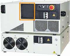
Use an Ethernet cable (prepared by yourself) to connect the Ethernet ports on the IPC and that inside the accessory panel on the front of the controller.
There are two Ethernet ports provided by the CPU board of the robot controller. The IP addresses of the two ports should be on different subnets. Ethernet port 1 (the upper one): usually used to connect the front panel of the controller; Ethernet port 2 (the lower one): usually reserved.
Set the IP Address
-
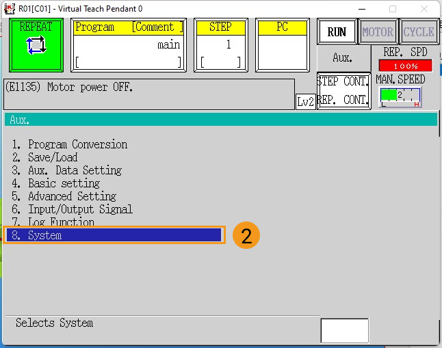
To set the IP address of the robot Ethernet port, press the Aux. button on the teach pendant, and then select .
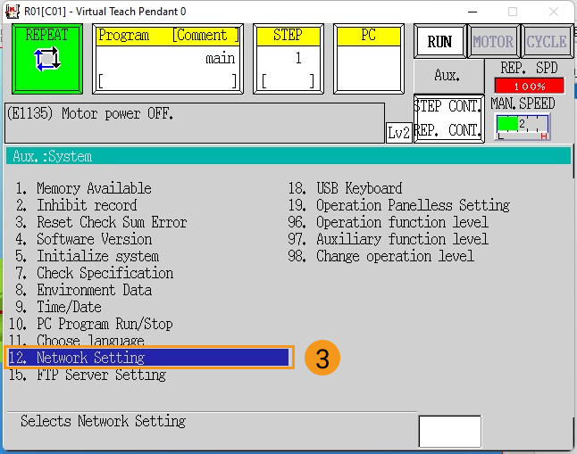
-
Set the IP address and subnet mask of port 1 on the Port 1 network setting page. The IP address of the robot must be on the same subnet as that IP address of the IPC’s Ethernet port. If a network gateway is used, set the Gateway parameter.
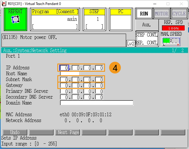
-
If port 2 on the robot is used for network connection, press the Next Page on the bottom of the Port 1 network setting page to enter the Port 2 network setting page.
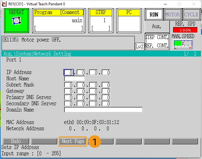
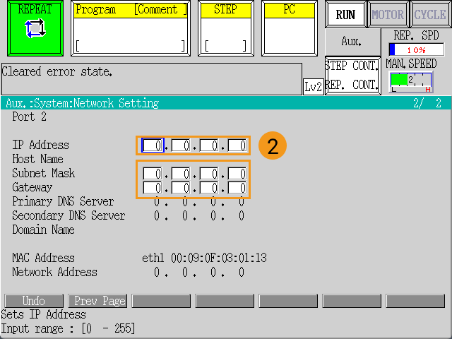
-
After the IP address is set, press the ENTER key on the teach pendant to confirm, and then restart the controller.
Set up “Robot and Interface Configuration” in Mech-Vision
-
Click Robot and Interface Configuration on the toolbar of Mech-Vision.
-
Select Listed robot from the Select robot drop-down menu, and then click Select robot model. Select the Kawasaki robot model that you use, and then click Next.
-
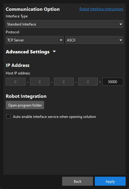
Select Standard Interface for Interface Type, and TCP Server and ASCII for “Protocol”, and then click Apply.
-
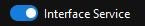
Make sure the Interface Service is started: on the toolbar of Mech-Vision, the Interface Service switch on the far right is flipped and turned to blue.
Load the Program Files to the Robot
Prepare the Files
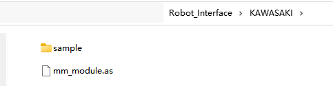
Navigate to Mech-Center\Robot_Interface\KAWASAKI under the installation directory of the Mech-Mind Software Suite, copy the mm_module.as file to the root directory of your USB flash drive, and insert the USB flash drive to the USB port inside the accessory panel on the controller.
Precautions for Loading Files
-
Save user programs.
If there are user programs in the program list on the teach pendant, save them before loading program files. If there are no user programs on the teach pendant, skip this step. -
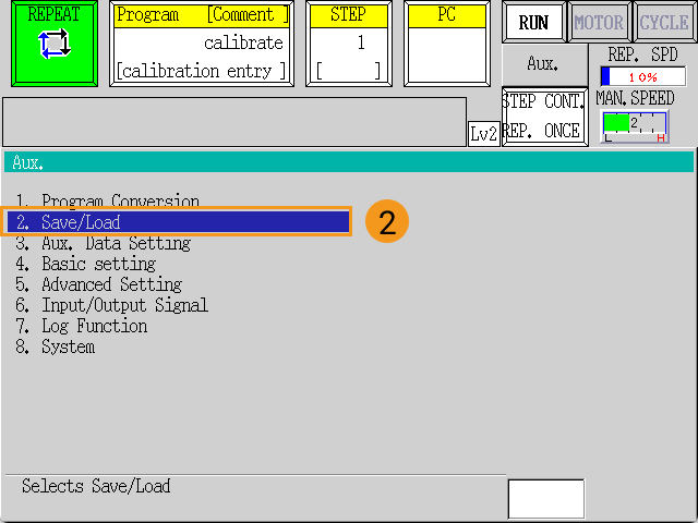
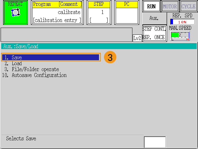
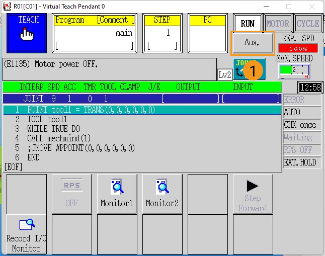
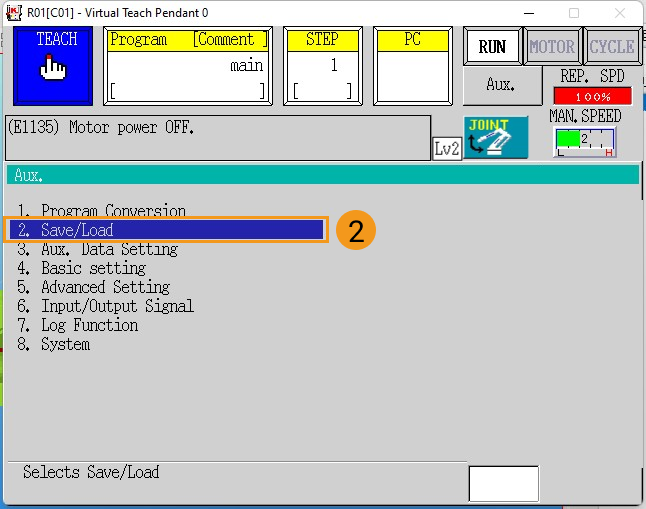
Press the Aux. button, and then select .
-
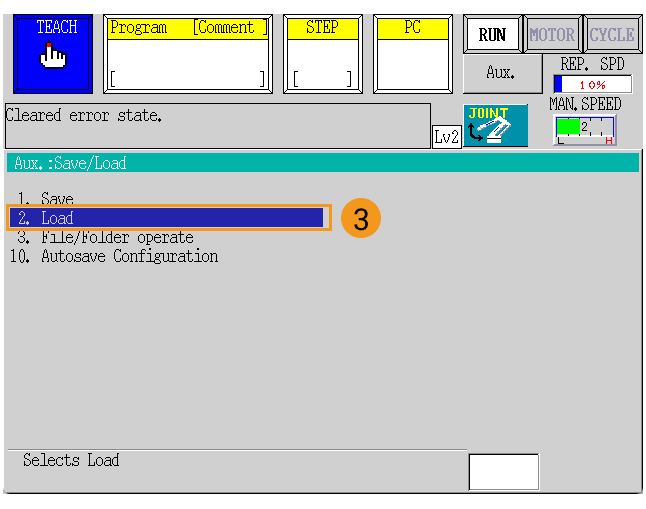
On the Save page, press Input File name to enter the file name, and then press the Save button. After the file is saved, press the
Rkey on the teach pendant to return to the main page.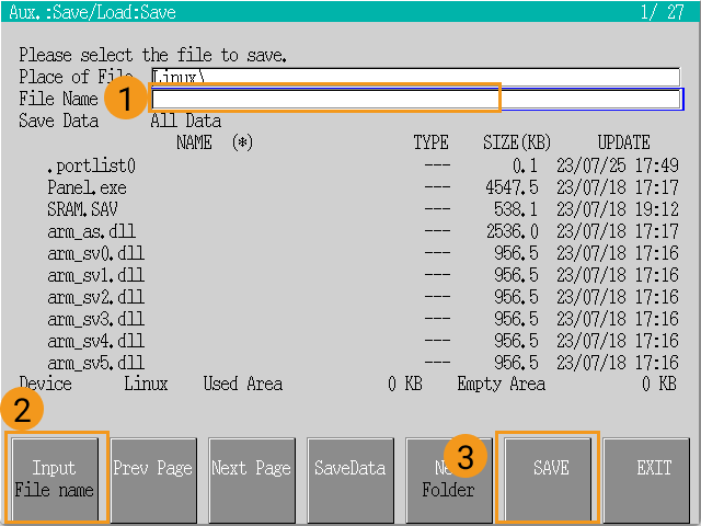
-
Before loading files, check if there are registered programs in the Program area on the teach pendant. If yes, kill these programs by following instructions as shown below.
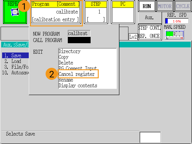
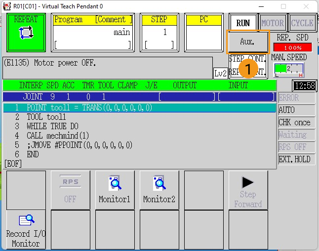
Make sure that the robot is in teach mode. After above checks, the interface of the teach pendant is shown as below.
Load the Program Files
-
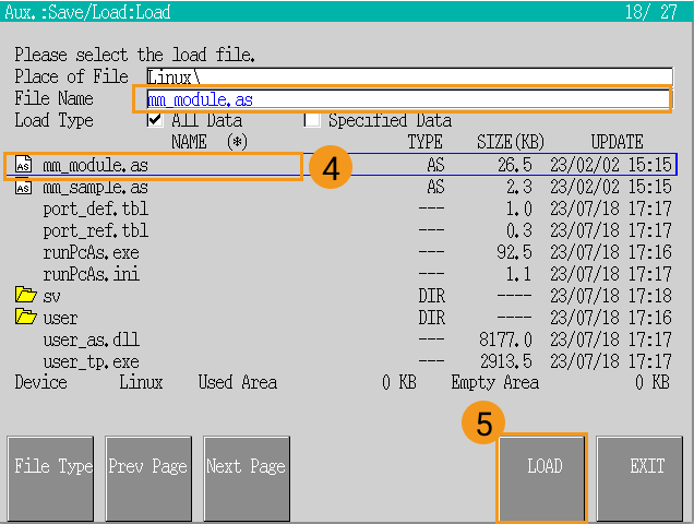
On the teach pendant, press the Aux. button, and select , press the program file mm_module.as twice to select it, and press LOAD when mm_module.as is displayed as “File Name”.
-
When loading completes, make sure that no errors occurred during loading. Press the
Rkey on the teach pendant to exit.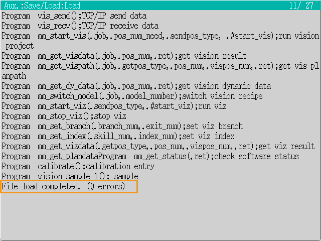
Test Robot Connection
Select and Modify the Program Used for Communication Test
|
Before you run the vision_sample_1 program, make sure that the following conditions are met:
|
-
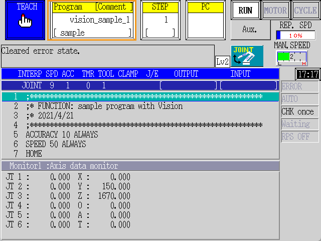
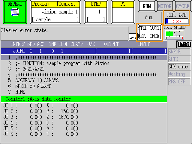
Select the vision_sample_1 frontend program on the teach pendant: Press the Program area, select vision_sample_1 from the Directory list, and then press the
ENTERkey to confirm.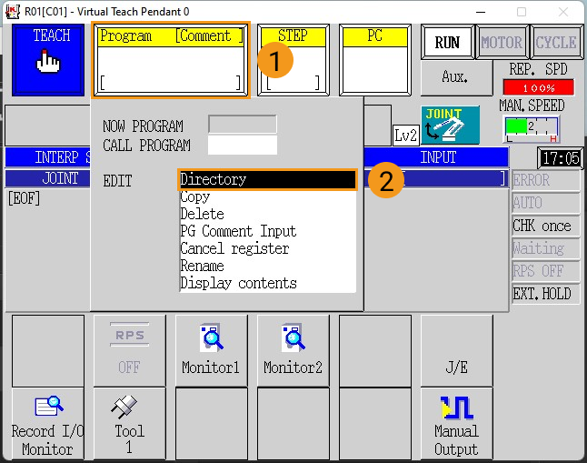
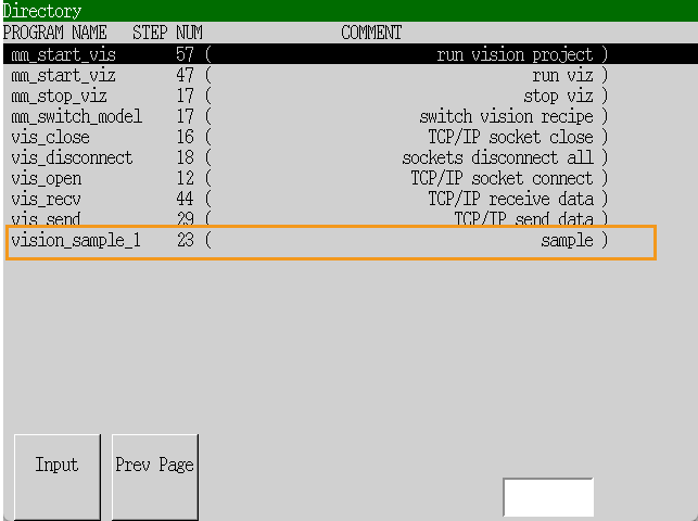
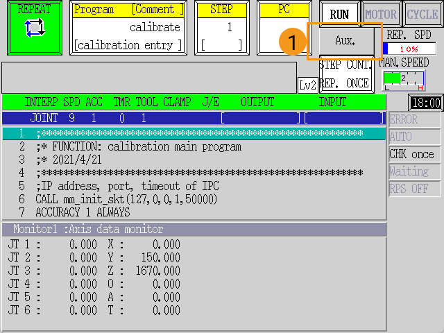
The following figure shows the interface after the program has been added.
-
Modify line 10 of the vision_sample_1 program: change “127, 0, 0, 1” to the actual IP address of the IPC, change “50000” to the host port number set in Mech-Vision.
-
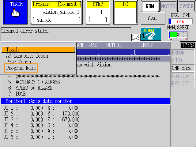
Press the
J/Ekey on the teach pendant, select Program Edit in the pop-up menu, and then press theENTERkey to confirm.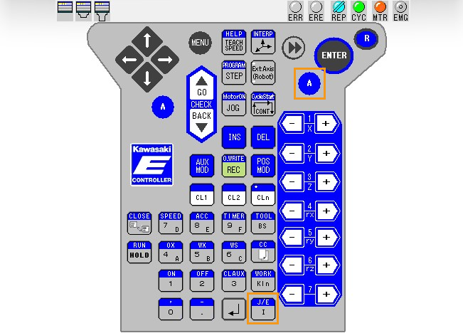
-
Select vision_sample_1 from the displayed program list, and press the
ENTERkey to confirm.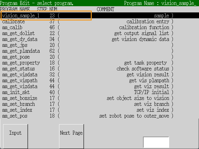
-
Use the arrow keys on the teach pendant to move the cursor to line 10, and then press the
ENTERkey to confirm.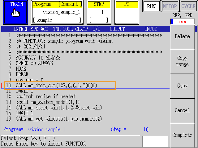
-
Use the arrow keys and number keys on the teach pendant to change the setting: change “127, 0, 0, 1” to the IP address of the IPC, and “50000” to the host port number set in Mech-Center. After the change, press the
ENTERkey to confirm, and then press theRkey to exit.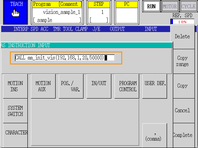
-
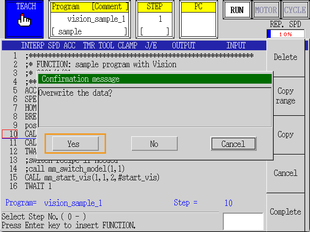
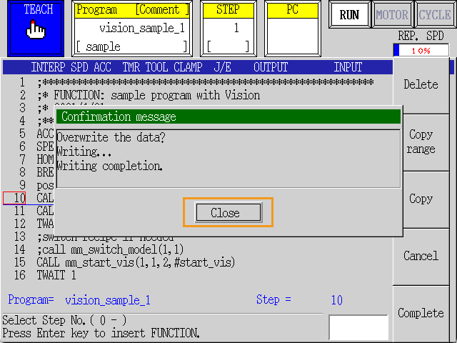
In the prompted Confirm window, press Yes, and then press Close.
-
Run the Test Program
-
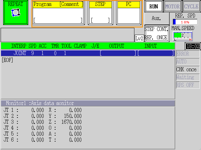
Switch the robot to the REPEAT mode, press RPT. SPD to adjust the repeat speed to 10%. Press the white button below Aux., to change the drop-down options to STEP CONT and REPEAT ONCE.
-
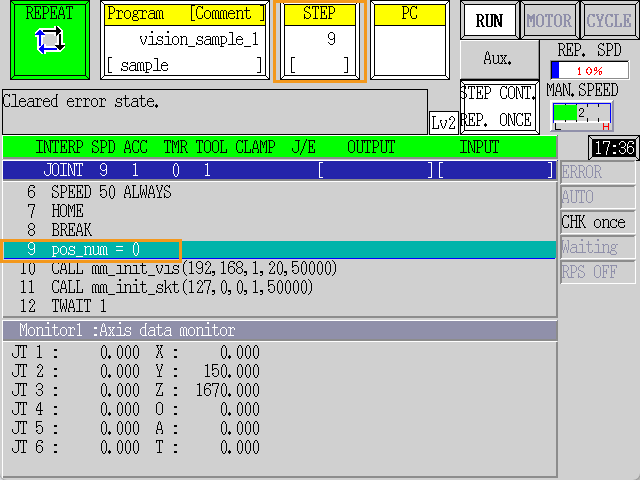
If the program is run from STEP 1, the robot will return to the HOME position according to the directive in line 7. For communication test, the robot does not need to return to the HOME position, and it only needs to stay still. To skip the directive in line 7, change STEP from 1 to 9 and then press the
ENTERkey.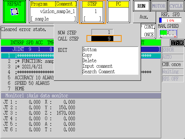
-
Hold the
Akey and press MOTOR on the teach pendant to make MOTOR lit. Hold theAkey and press CYCLE on the teach pendant to make CYCLE lit. If RUN does not turn green, press theRUN/HOLDkey while holding theAkey.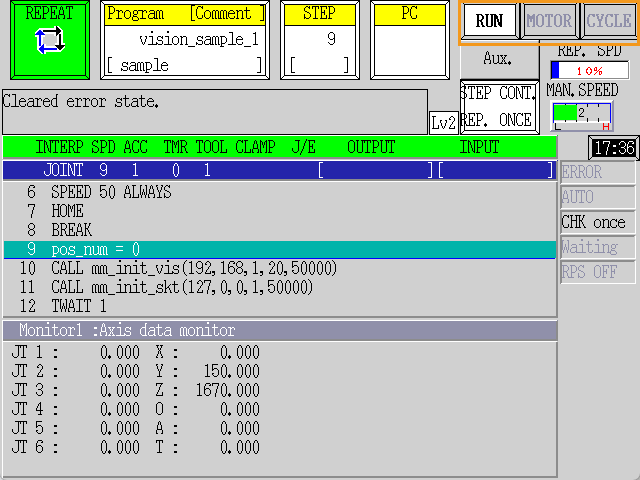
-
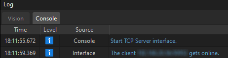
If the robot is connected successfully, the Console tab of Mech-Vision Log panel will display a log indicating the client is connected.