Communication Configuration and Example Program Usage
This topic provides instructions on setting up the Standard Interface communication based on the Siemens PLC Snap7 protocol between a Siemens SIMATIC S7 PLC and Mech-Mind Software Suite using the TIA Portal software.
Hardware and Software Requirements
Hardware
-
The following S7 series PLCs from Siemens are supported:
-
S7-300: Integrated PN network port or CP343-1
-
S7-400: Integrated PN network port or CP443-1
-
S7-1200: None
-
S7-1500: None
-
-
Power adapter: 220V AC to 24V DC
-
Mech-Mind Vision System IPC or host
-
Ethernet cable
Software
-
Siemens PLC programming software TIA Portal V15.1
-
Mech-Mind Software Suite: 1.7.0 to 1.7.4
-
Interface file for S7 communication between software Siemens Tia Portal and Mech-Mind Software Suite:
-
Data block file MM Interface.db for data communication
-
File MM Interface Program.scl for implementing the functions of various interface commands.
-
The files are located in Mech-Center/Robot_Interface/Siemens Snap7/TIA Portal in the installation directory of Mech-Mind Software Suite on the IPC or host. Please copy the file to the computer where the TIA Portal software is installed.
|
Create and Configure the PLC Project
Create a PLC Project
-
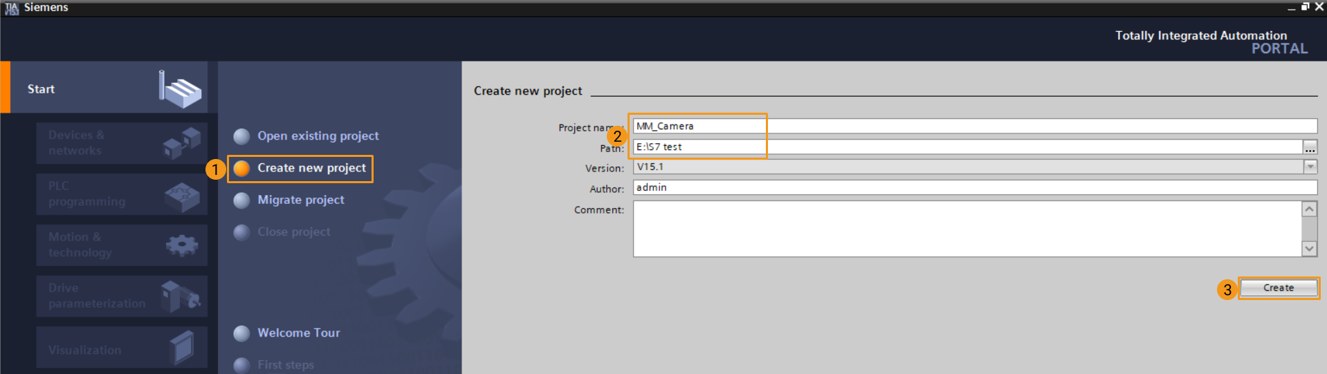
Open TIA Portal, click Create new project, enter Project name, select a Path, and click Create. A new window will pop up. Click Open project view.
-
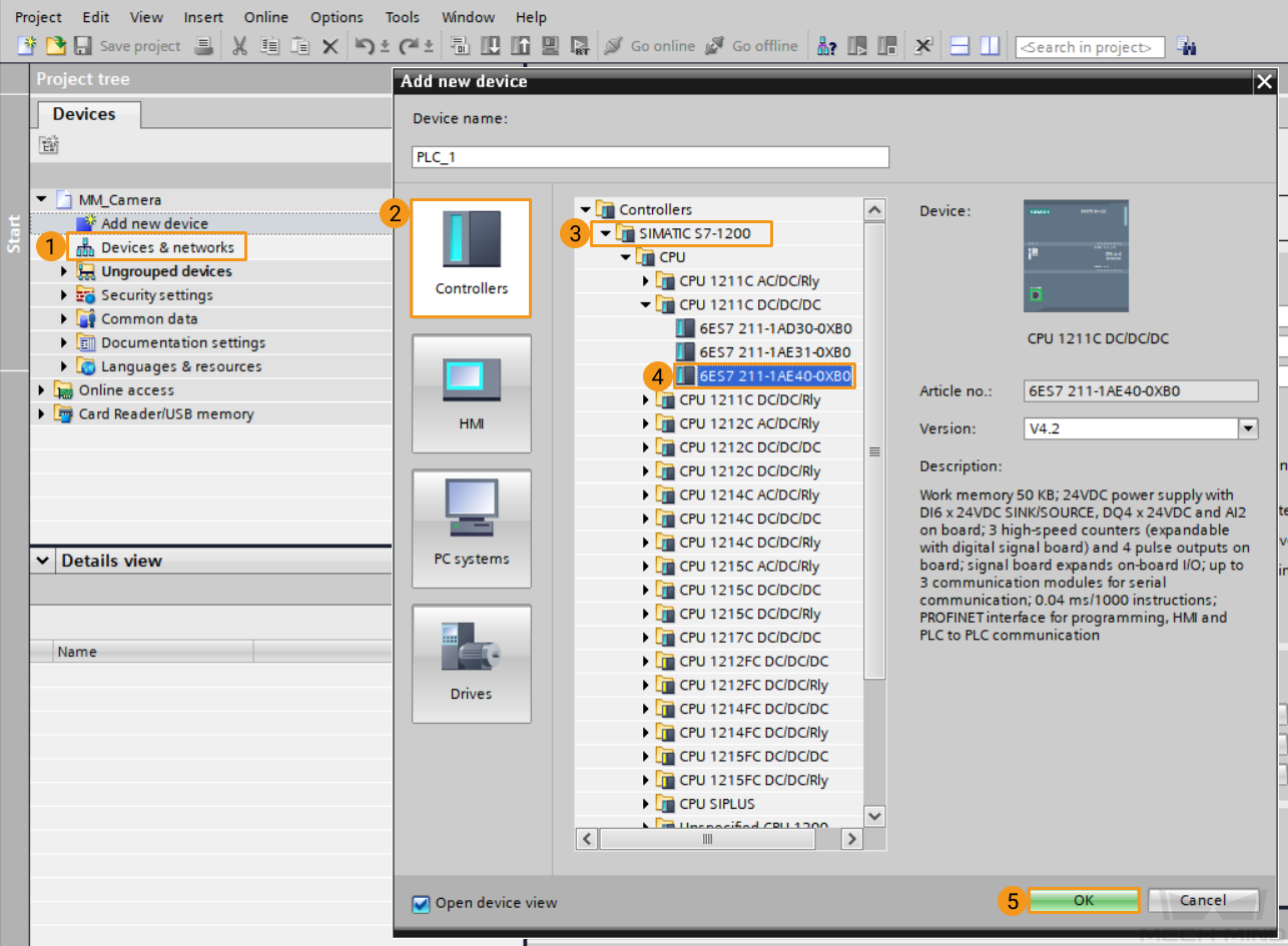
In the Project tree section, double-click Add new device to open the window. Under Controllers, select the module that is consistent with the physical PLC. The default device name can be used. Click OK.
-
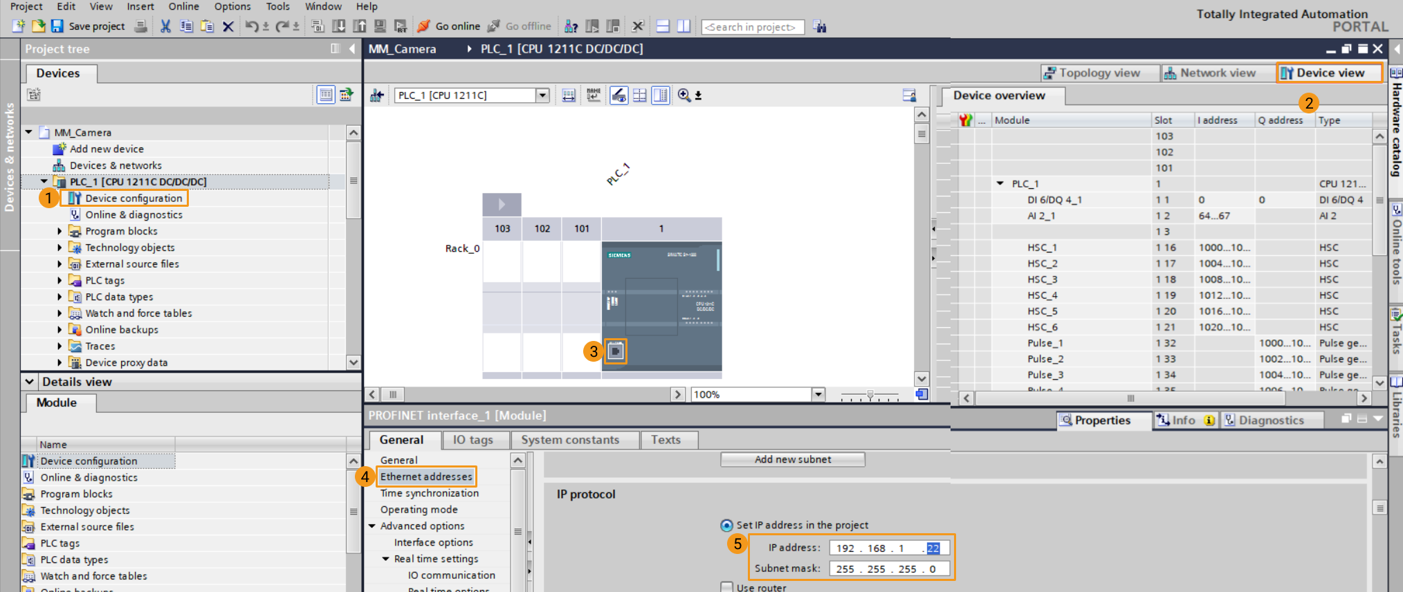
On the device configuration page, click Device view, then double-click the network port label of PLC_1. On the Properties/General page, click Ethernet address and set the IP address to 192.168.1.22. The default subnet mask can be used (should be in the same network segment as the vision system’s IPC).
-
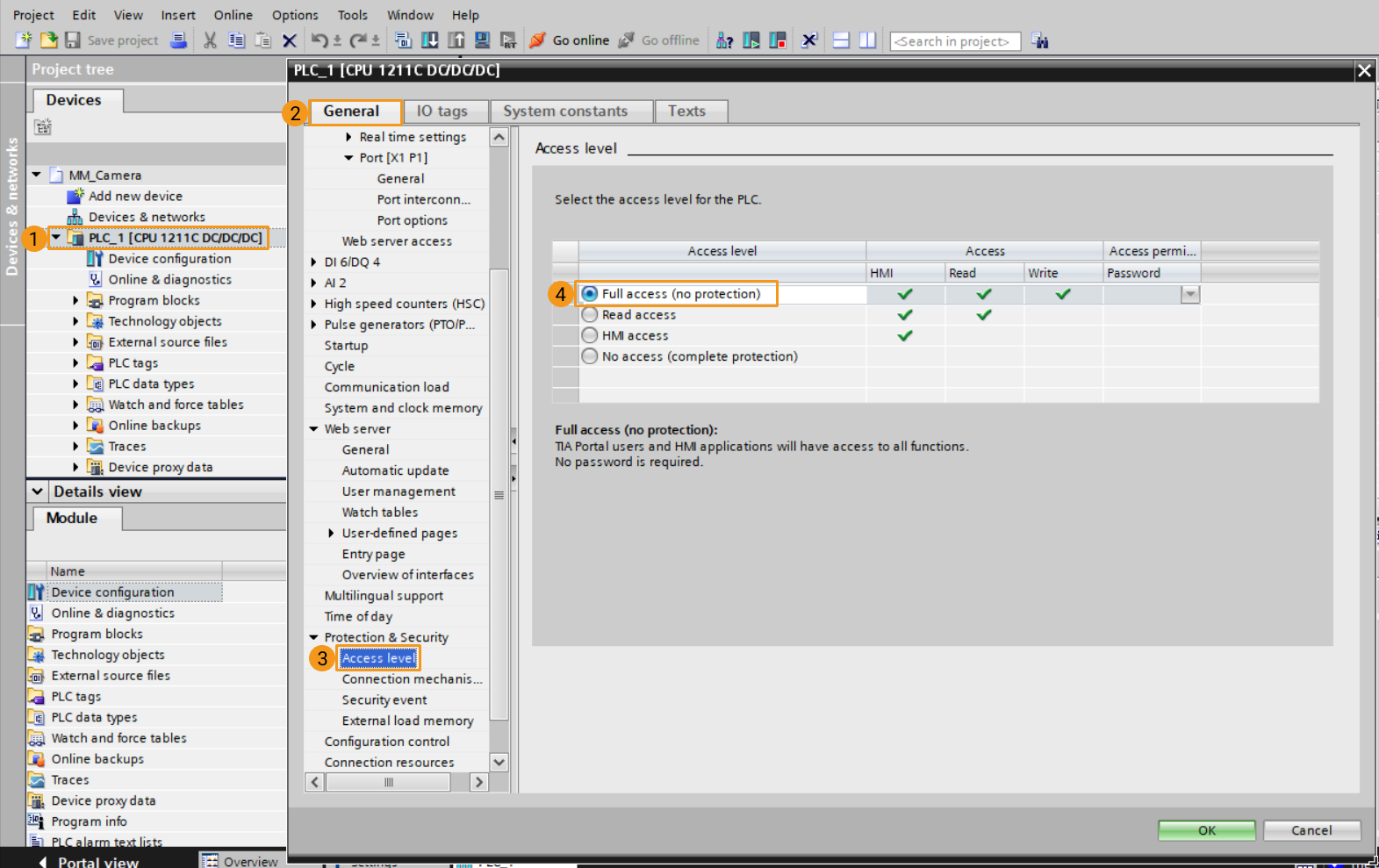
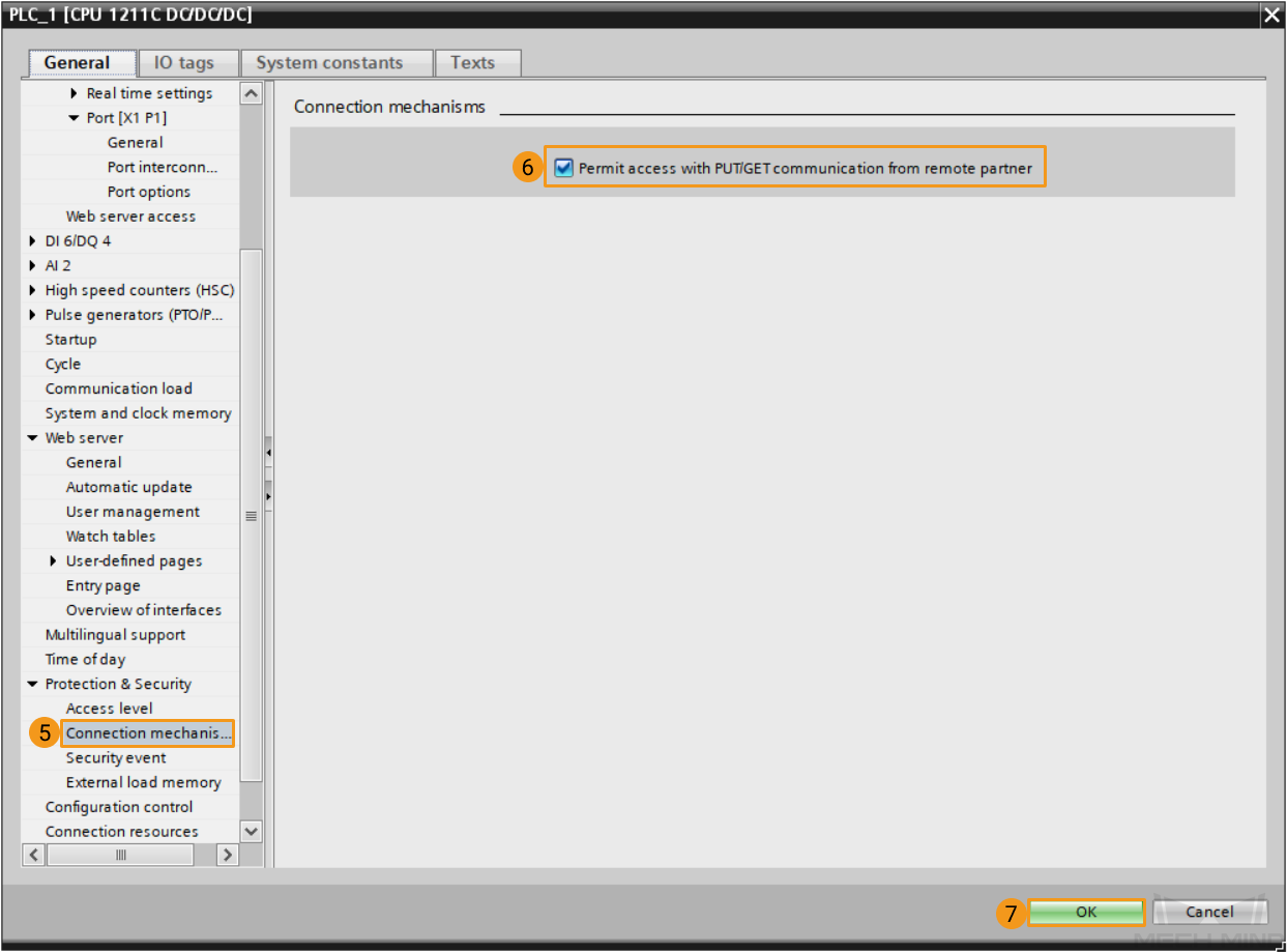
Select the device PLC_1 in the project tree, right-click and select Properties, and enter the interface in turn in the pop-up window. Under Access level, check Full access (no protection). Under Connection mechanisms, check Permit access with PUT/GET communication from remote partner. Click OK to save the project.
Import the S7 Communication Interface File
-
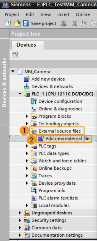
Under the project tree, click External source files and Add new external file. In the pop-up window, select files MM Interface.db, MM Interface Program.scl, and click Open to import the files to the new project.
-
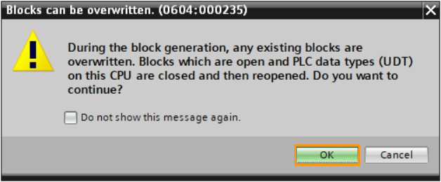
Select the newly imported external source files (select MM Interface.db first, then select MM Interface Program.scl), right-click, and select Generate blocks from source. Click OK in the pop-up window (this operation will overwrite the functions and data blocks with the same names in the project, and automatically select an unoccupied number).
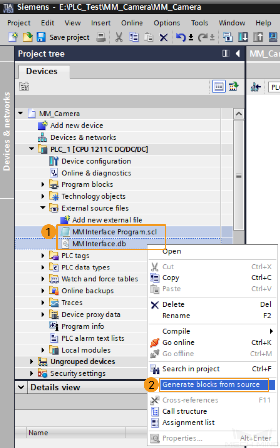
If the operations are not performed in the order of the selected files above, an error message will appear in the log window. -
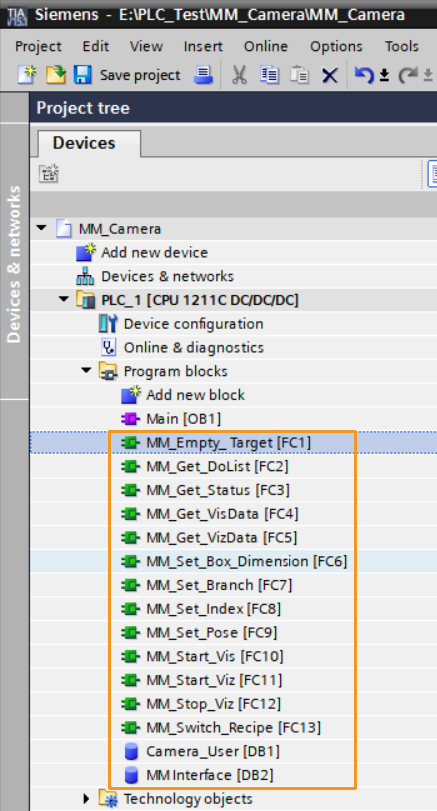
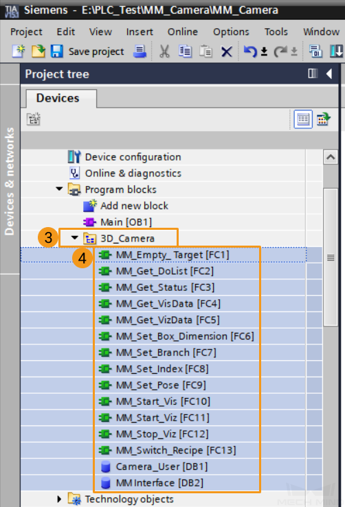
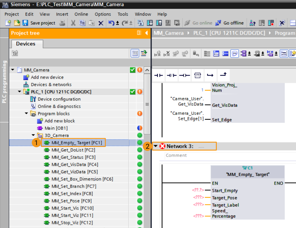
The functions and data blocks generated by the external source file are as follows, where the DB number of MM Interface must be consistent with the DB number set in Robot and Interface Configuration in Mech-Vision. The DB Camera_User is used to store user data.
-
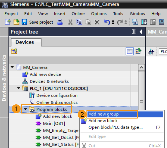
In the project, to facilitate the maintenance of functions and data blocks, you can right-click the program block, select Add new group, name it “Mech-Mind”. Then, select all the newly generated function functions and data blocks and move them to the group folder.
Download the S7 Communication Interface File
-
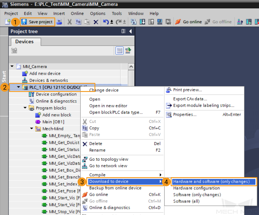
Click Save project, then in the project tree, right-click the new project PLC_1. Select in turn, and the download window will pop up.
-
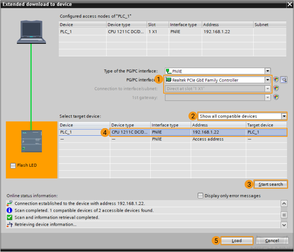
In the pop-up download window, select the network card driver connected to PLC for PG/PC interface, select Direct at slot ‘1 X1’ for Connection to interface/subnet, select Show all compatible devices for Select target device, and then click Start search. Select the detected CPU device, click Download, click Finish after the download is complete.
Configure IPC and Initiate Communication
Set up “Robot and Interface Configuration” in Mech-Vision
-
Ensure that the IP address of the IPC is on the same subnet as the PLC, for instance, 192.168.1.10. Open Command Prompt on the IPC and ping the PLC IP address to check if they are connected successfully.
-
Click Robot and Interface Configuration on the toolbar of Mech-Vision.
-
Select Listed robot from the Select robot drop-down menu, and then click Select robot model. Select the robot model that you use, and then click Next.
-
In the Communication Option panel, follow the steps below to proceed:
-
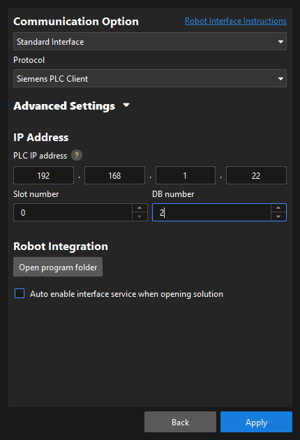
Interface Type: Standard Interface
-
Protocol: Siemens PLC Client
-
PLC IP address: 192.168.1.22 (according to the setting in SIMATIC Manager)
-
Slot number: 1; DB number: 2 (the number of “MM Interface” in the PLC project). Lastly, click Apply.
-
Check Communication
-
Make sure the Interface Service is started: On the toolbar of Mech-Vision, the Interface Service switch on the far right is flipped and turned to blue. The PLC is successfully connected if the Console tab of Mech-Vision Log panel displays Connect to PLC server successfully. If not, please check the configuration and check whether the physical connection is normal.

-
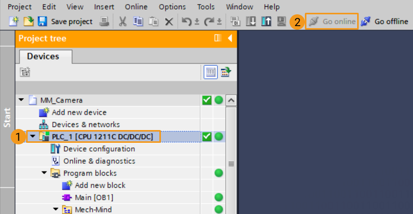
Return to the main interface of TIA Portal, select the device PLC_1, and click Go online.
-
Under of the project tree, double-click the data block MM Interface, then click Monitor all
 . If the connection is established successfully, the monitor value of Heartbeat will keep changing.
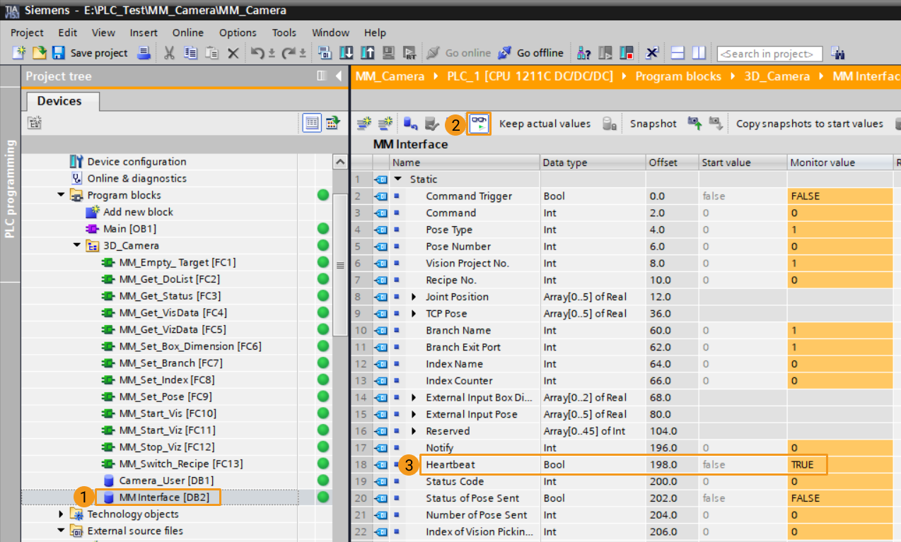
Test with Vision Projects
This section describes how to use the Siemens PLC Client interface program for the startup and data acquisition of Mech-Vision and Mech-Viz projects. For the specific functions and introduction of Siemens PLC Snap 7 communication parameters, please see Siemens PLC.
Prerequisites
-
Create a Mech-Vision solution. Right-click the solution and select Autoload Solution. Projects in the solution are also autoloaded. Meanwhile, the project number will show up before each project name.
-
Create a Mech-Viz project. Right-click the project name in Resources in Mech-Viz and select Autoload Project.
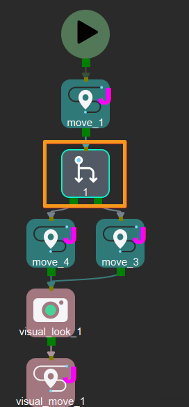
The Mech-Viz project used for testing should contain a “Branch by Msg” Step that has been renamed to 1 as shown below.
Run Mech-Vision Project and Obtain Vision Points
Configure Programs
-
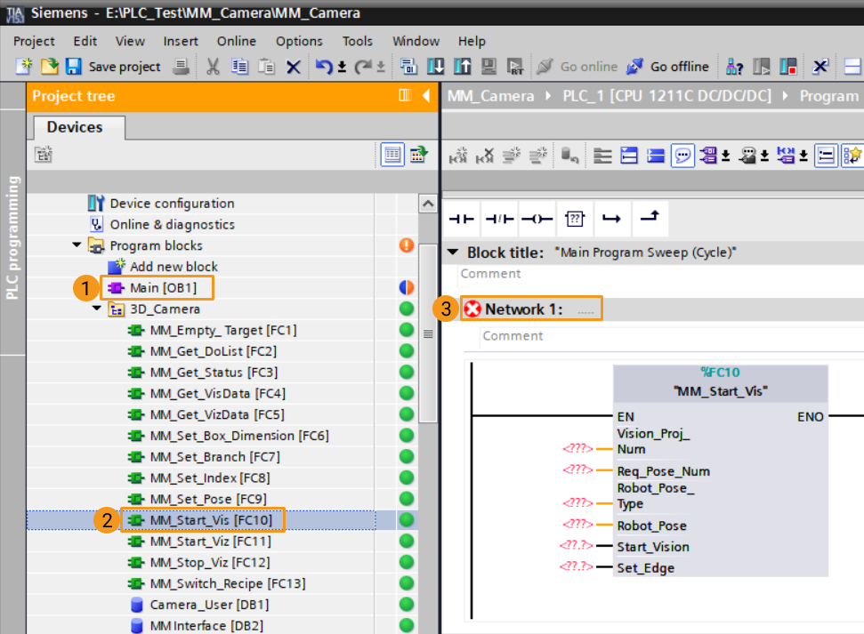
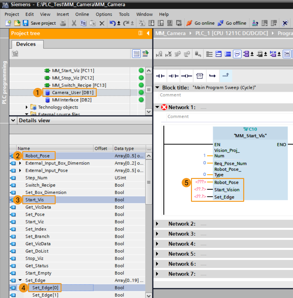
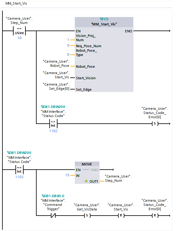
In the main interface of TIA Portal, under the , double click under Program blocks, and drag the function MM_Start_Vis to Network 1 of the main program.
-
Set Mech-Vision project ID. Change the value of the Vision_Proj_Num port to the ID of the Mech-Vision project you wish to run. For example, if the value is changed to 1, then project No.1 in Mech-Vision will be started.
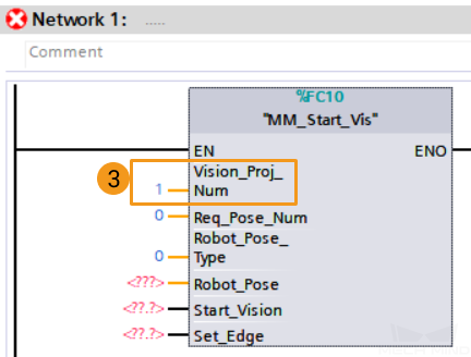
-
Set the number of poses to be sent by Mech-Vision project. In this example, set the port value of Req_Pose_Num to 0, indicating expecting that all the poses in the vision result should be returned from Mech-Vision.
-
Set the type of pose to be sent by the robot. In this example, set the port value of Robot_Pose_Type to 0, indicating no image-capturing pose needs to be read from the robot (such as in the Eye-to-Hand mode).
-
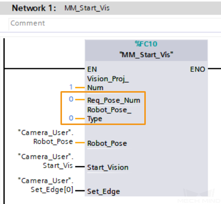
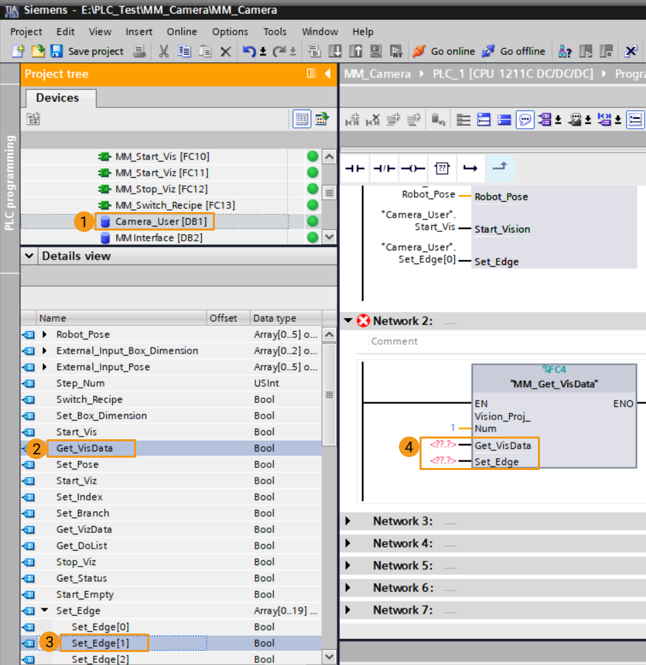
Under the project tree, click the data block Camera_User, and drag the parameters under Details view to the corresponding ports of MM_Start_Vis.
-
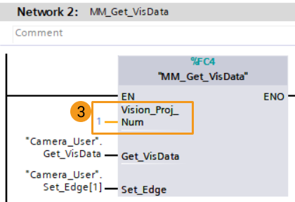
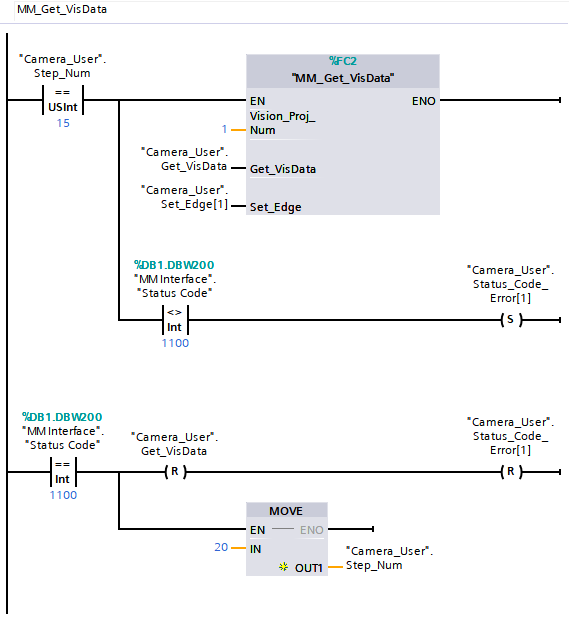
Drag the MM_Get_VisData function to Network 2 of the main program.
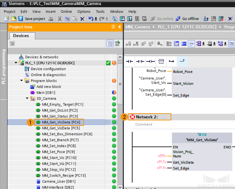
-
Set Mech-Vision project ID, namely, the number before the project name in the project list in Mech-Vision. Set the port value of Vision_Proj_Num to 1, and the vision recognition result of Project No.1 in Mech-Vision will be obtained.
-
Under the project tree, click data block Camera_User, and drag the parameters under Details view to the corresponding ports of MM_Get_VisData.
-
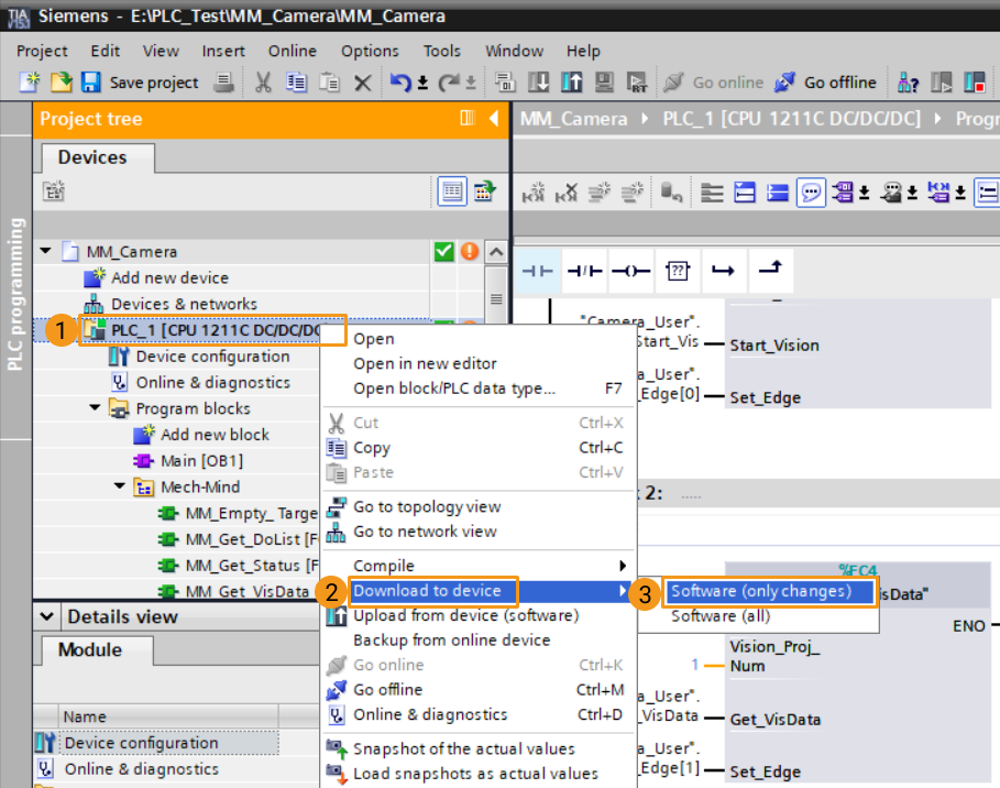
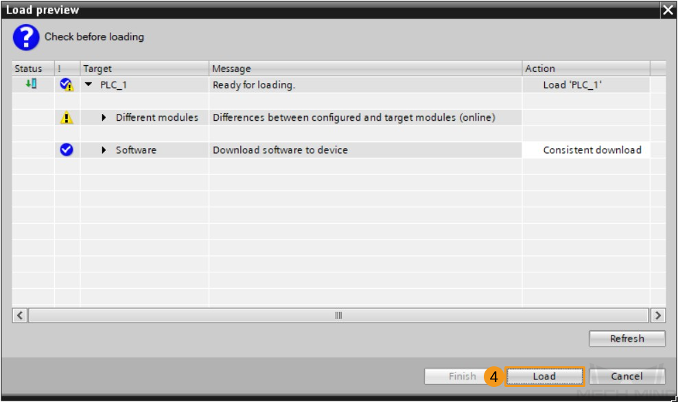
Under the project tree, click to select PLC_1, select . Click Load in the pop-up download window to download the latest program to the PLC.
Trigger Mech-Vision Project to Run
-
In the main program window of Main [OB1], click Enable/Disable Monitoring
to enable monitoring.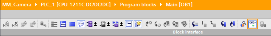
-
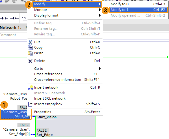
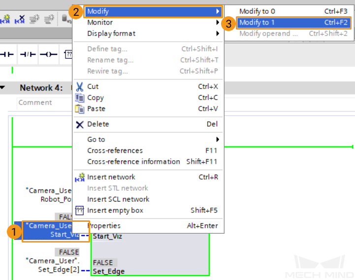
Right-click the input-side parameter “Camera_User”.Start_Vis of MM_Start_Vis and change its value to 1 to trigger the running of the Mech-Vision project, and then reset this parameter. At this time, the parameter StatusCode of MM Interface should have a returned value of 1102. Otherwise, an error has occurred, and please see Status Codes and Troubleshooting for further instructions.
Get Vision Target(s) Calculated by Mech-Vision
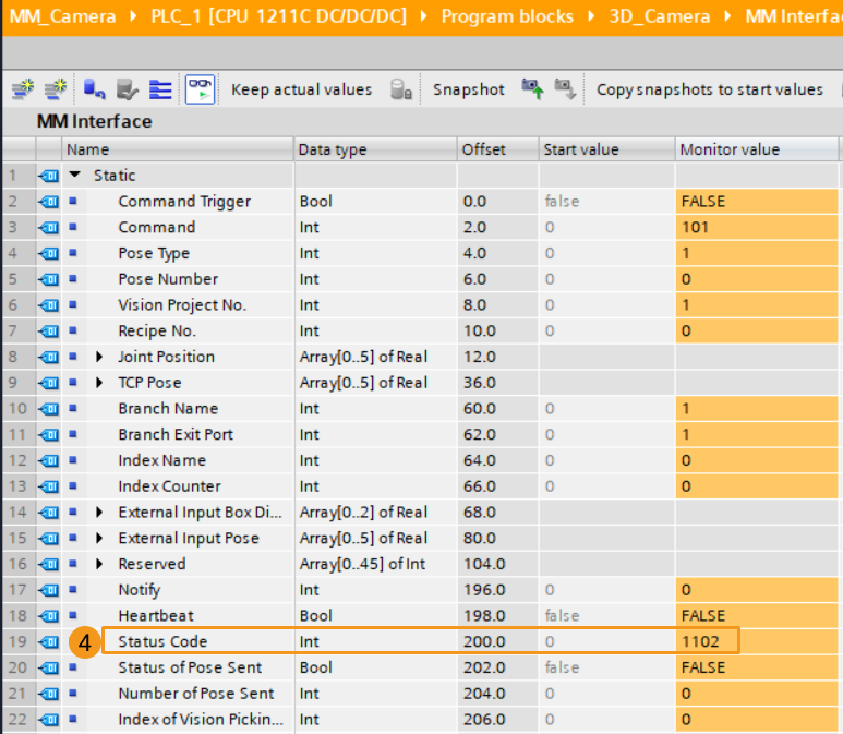
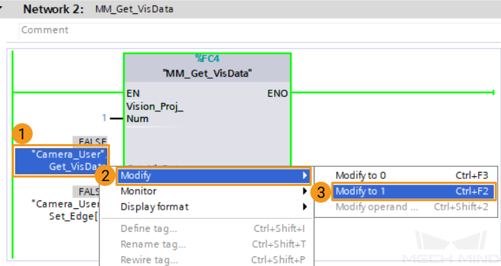
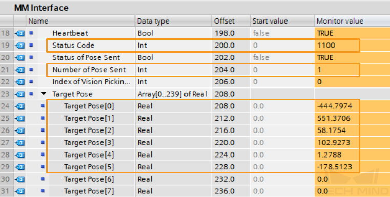
Right-click the input-side parameter “Camera_User”.Start_Vis of MM_Get_VisData and change its value to 1 to obtain the vision result, and reset its value. At this time, the parameter StatusCode of MM Interface should have a returned value of 1100. Otherwise, an error has occurred, and please see Status Codes and Troubleshooting for further instructions. Otherwise, an error has occurred, and please see Status Codes and Troubleshooting for further instructions.
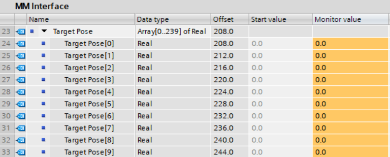
The returned data from MM Interface is as follows. The value of “Number of Pose Sent” is 1, meaning 1 pose has been obtained. The pose data is stored in “TargetPose”.
Run Mech-Viz Project and Obtain Planned Path
Configure Programs
-
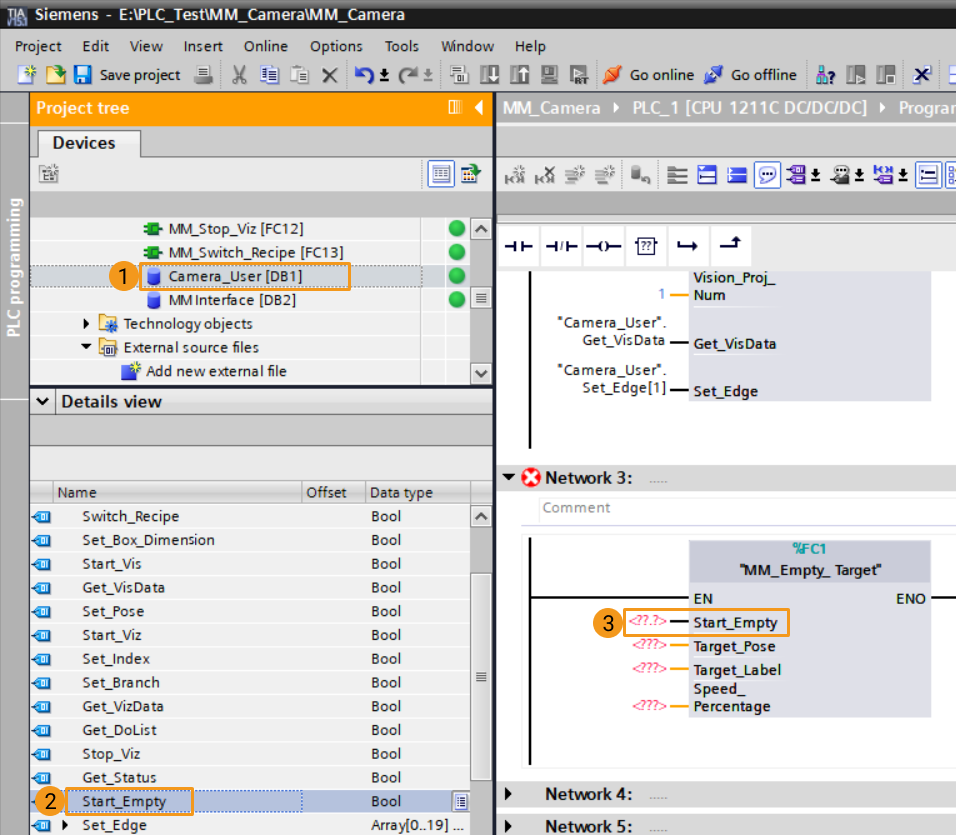
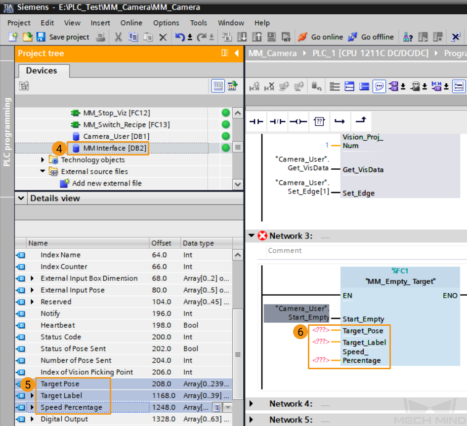
Drag the function MM_Empty_ Target to Network 3.
-
Click the data blocks Camera_User and MM Interface respectively, and drag the parameters in the detailed view to the corresponding input-side ports of MM_Empty_Target.
-
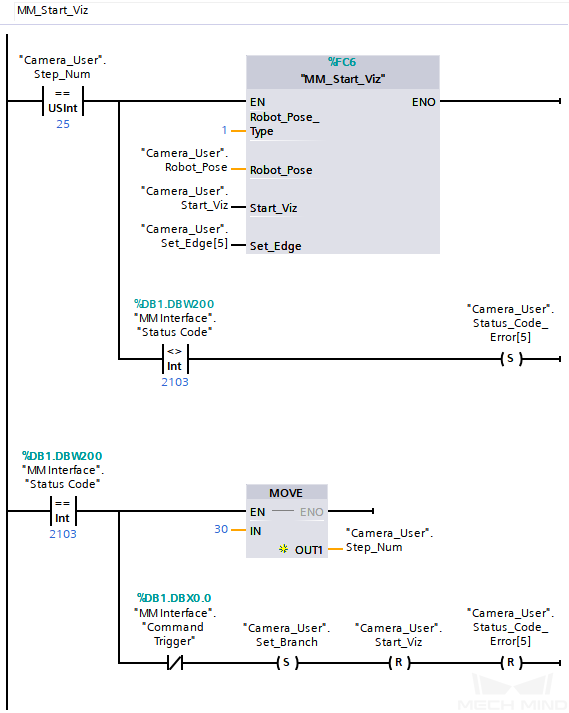
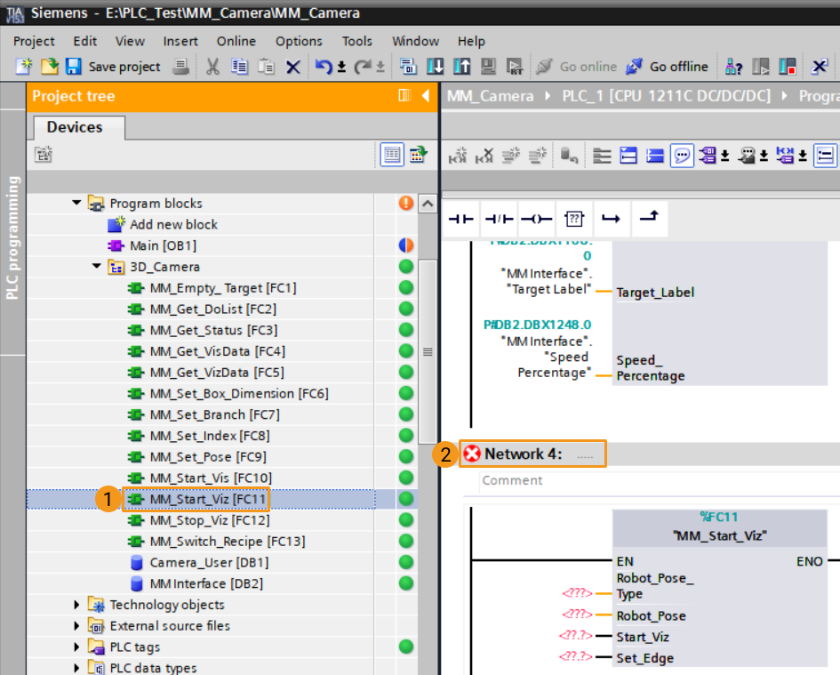
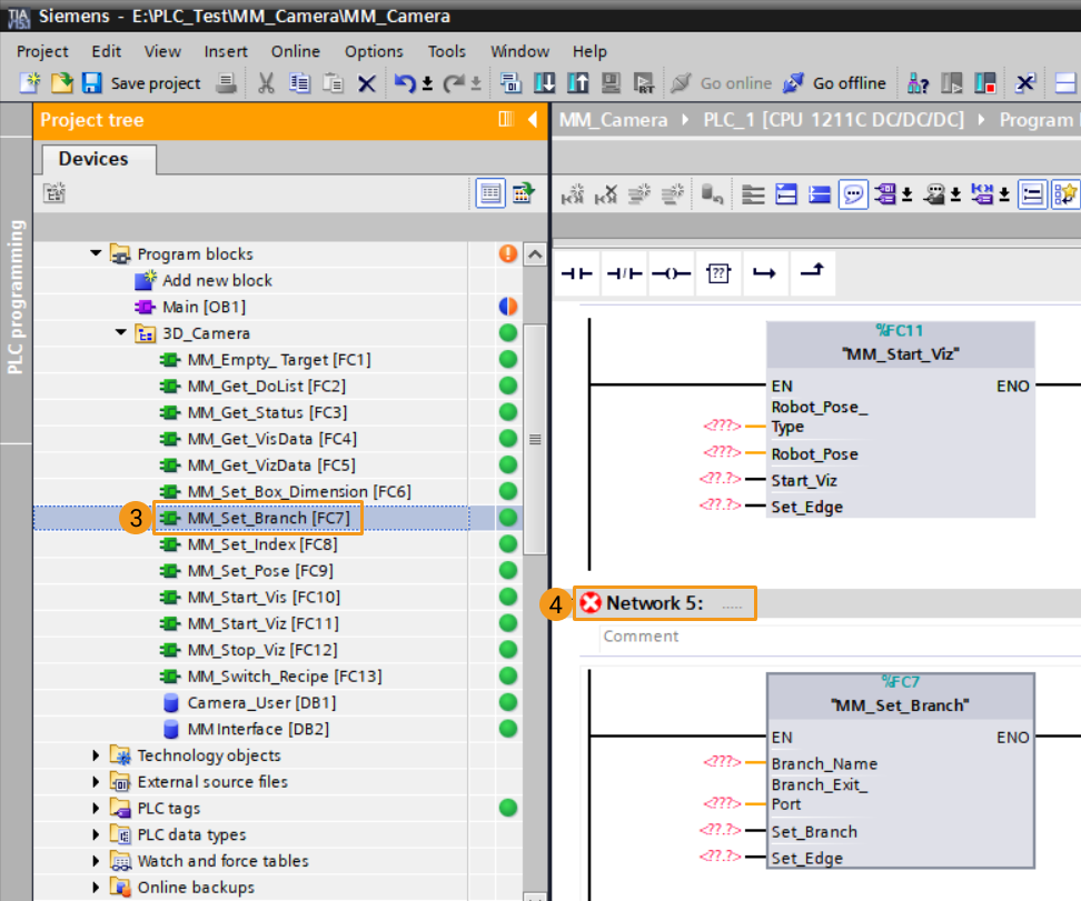
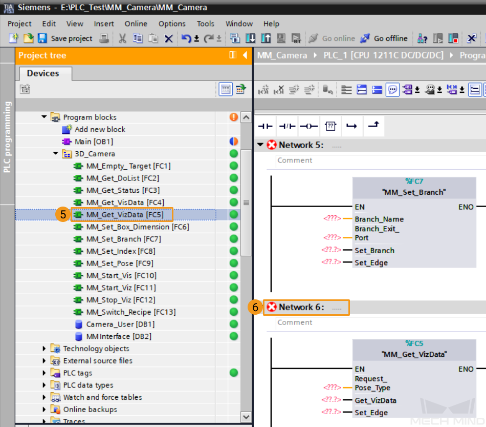
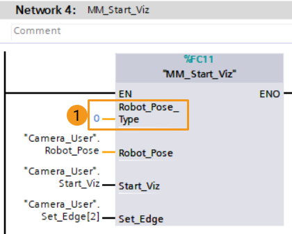
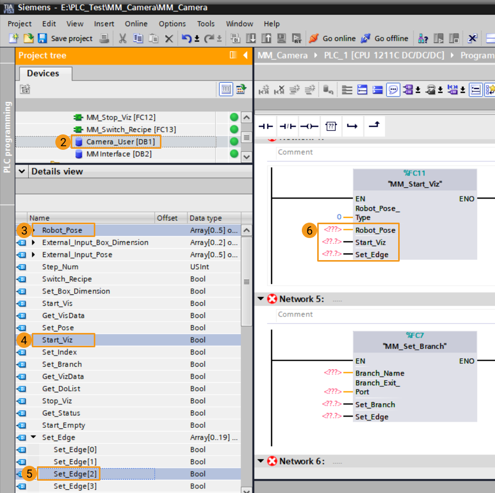
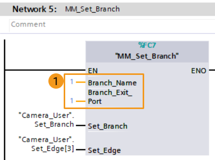
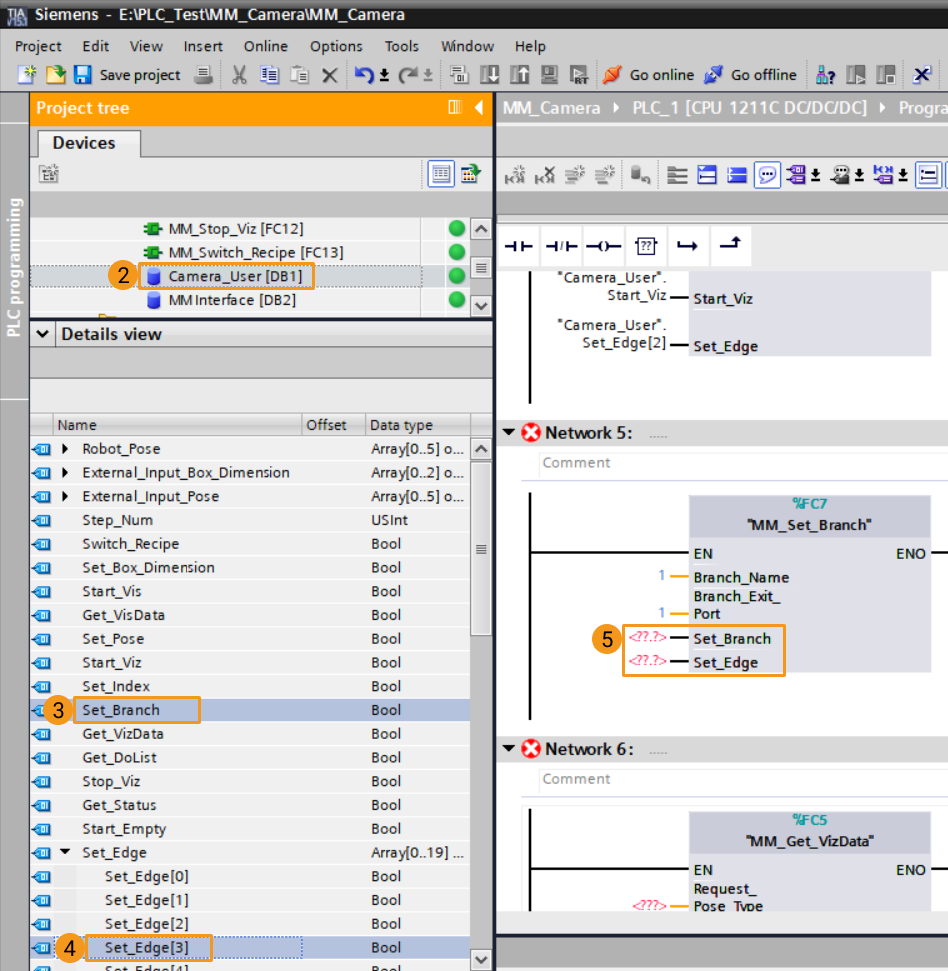
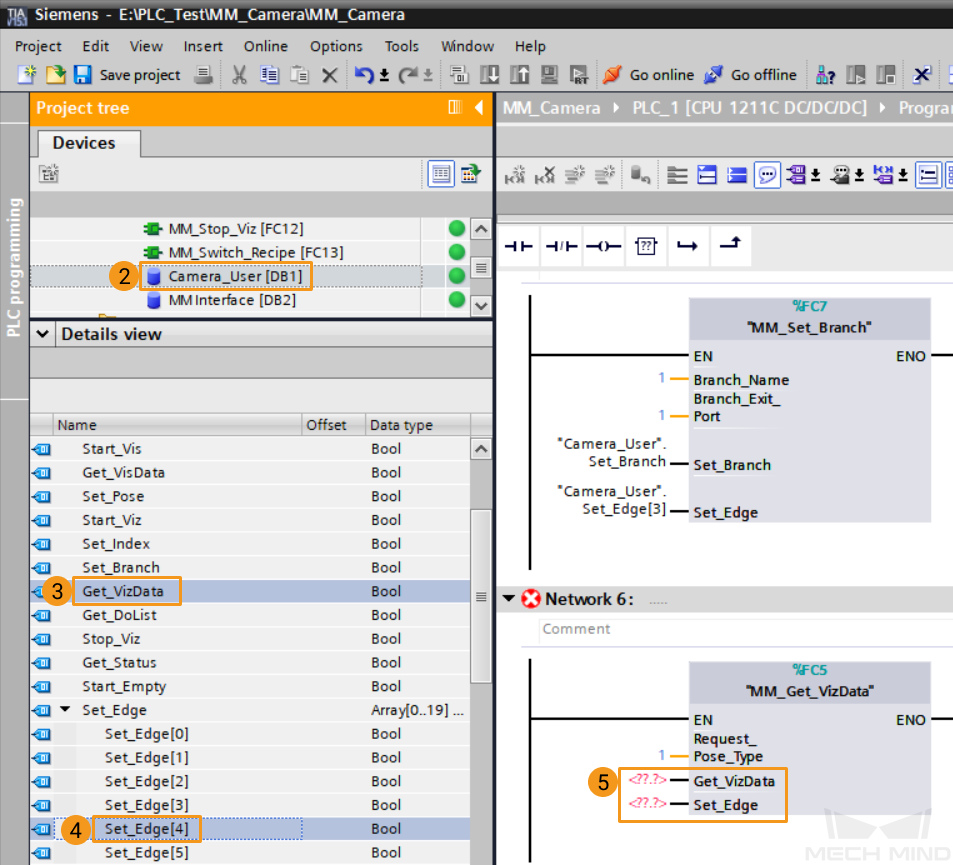
Drag and drop the functions MM_Start_Viz, MM_Set_Branch, MM_Get_VizData to Network 4, 5, and 6 respectively.
-
Set the type of pose to be sent by the robot. In this example, set the port value of Robot_Pose_Type to 0, indicating no image-capturing pose needs to be read from the robot (such as in the Eye-to-Hand mode). Click the data block Camera_User, and drag the parameters in the detailed view to the corresponding input-side ports of MM_Start_Viz.
-
Set the branch parameters in Mech-Viz project. In this example, set the port values of Branch_Name and Branch_Exit_Port to 1 respectively, which means that when the Mech-Viz project is controlled to execute to branch 1, it will continue to execute along exit 1. Click the data block Camera_User, and drag the parameters in the detailed view to the corresponding input-side ports of MM_Set_Branch.
-
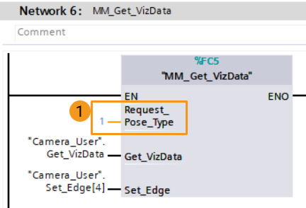
Set the expected type of waypoints on the planned path. In this example, set the port value of Request_Pose_Type to 1, indicating the expected waypoint pose type is JPs. Click the data block Camera_User, and drag the parameters in the detailed view to the corresponding input-side ports of MM_Get_VizData.
In this example, Request_Pose_Type and Robot_Pose_Type in the functions MM_Start_Vis and MM_Start_Viz correspond to the same parameter Pose Type in MM Interface. If the set values are different, they cannot take effect at the same time. -
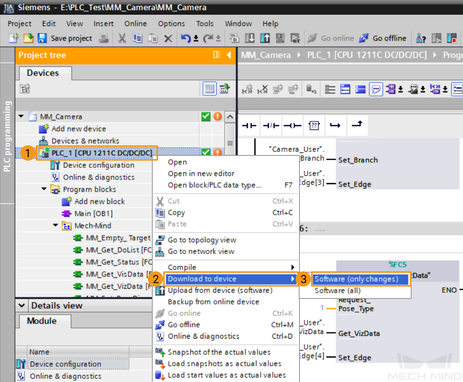
Under the project tree, click to select PLC_1, select . Click Load in the pop-up download window to download the latest program to the PLC.

Trigger Mech-Viz Project to Run
-
In the main program window of Main [OB1], click Enable/Disable Monitoring
to enable monitoring.
-
Right-click the input-side parameter “Camera_User”.Start_Empty of MM_Empty_Target, set its value to 1 to empty the vision result obtained in the last round, and then reset its value.
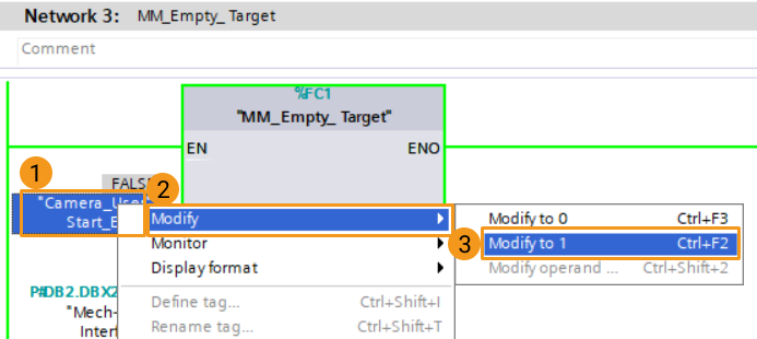
At this time, the value of the data block Target Pose of MM Interface has been cleared.
-
Right-click the input-side parameter “Camera_User”.Start_Viz of MM_Start_Viz, set its value to 1 to start the running of the Mech-Viz project and then reset its value. At this time, the parameter StatusCode should have a returned value of 2013. Otherwise, the corresponding error code will be returned. Please refer to Status Codes and Troubleshooting for troubleshooting.
Set Mech-Viz Branch Exit Port
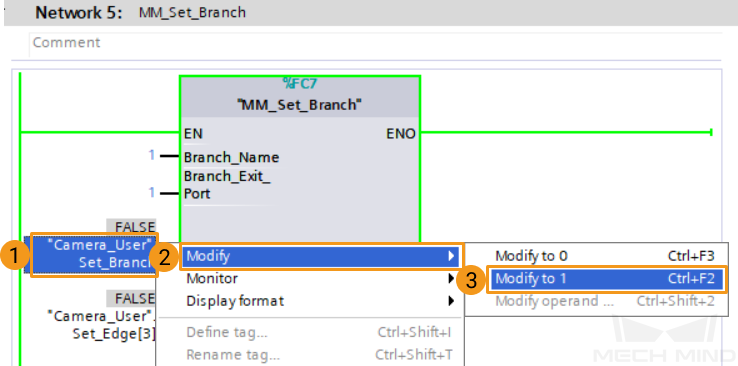
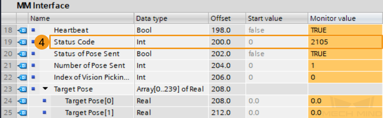
Right-click the input-side parameter “Camera_User”.Set_Branch of MM_Set_Branch, set its value to 1 to specify the branch exit, and then reset its value. At this time, the parameter StatusCode should have a returned value of 2105. Otherwise, the corresponding error code will be returned. Please refer to Status Codes and Troubleshooting for troubleshooting.
Get Mech-Viz Planned Path
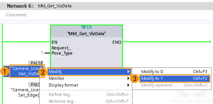
Right-click the input-side parameter “Camera_User”.Get_VizData of MM_Get_VizData, set its value to 1 to obtain the planned path from Mech-Viz and then reset its value. At this time, the parameter StatusCode should have a returned value of 2100. Otherwise, the corresponding error code will be returned. Please refer to Status Codes and Troubleshooting for troubleshooting.
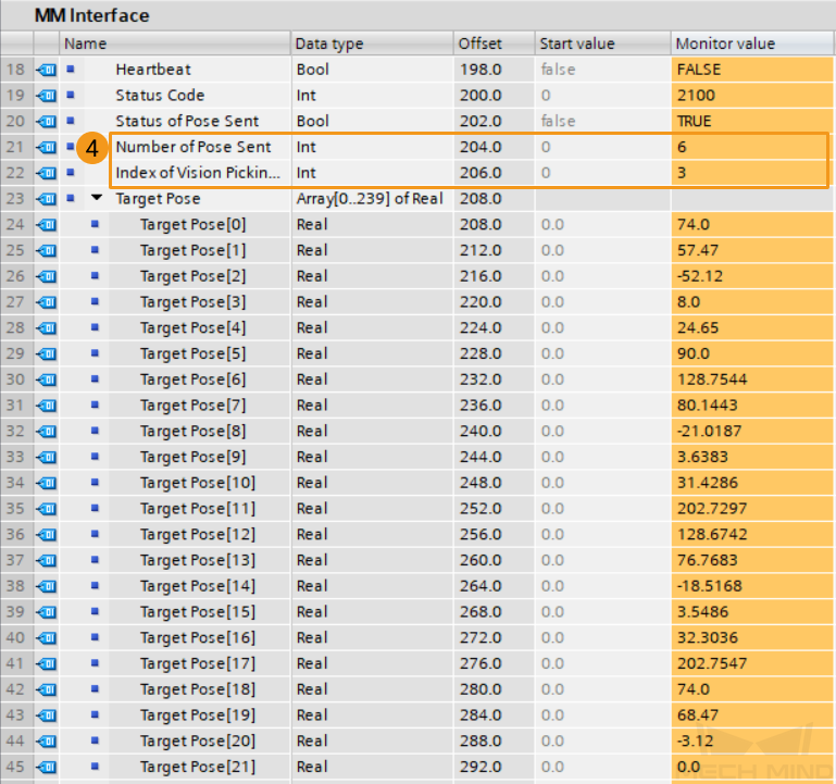
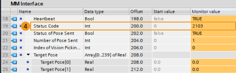
The returned data of MM Interface is as follows. The value of Number of Pose Sent is 6, which means that 6 sets of JPs data are obtained, and the data is stored in Target Pose. Index of Vision Move is 3, indicating that the position number of the vision point, i.e., the Vision Move Step in the path, is 3.