Set up Standard Interface Communication with FANUC
This topic introduces the process of setting up the Standard Interface communication with a FANUC robot.
Check Controller and Software Compatibility
-
FANUC robot: 6-axis or 7-axis
-
Controller system software version: V8.* and V9.*
-
Additional controller software packages:
R651 or R632 (karel)
R648 (User Socket Msg)
Set up the Network Connection
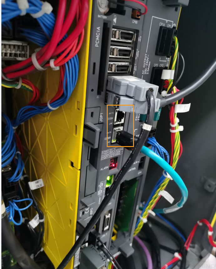
Hardware Connection
Plug the Ethernet cable of the IPC into the Ethernet port of robot controller as shown in the figure. You can plug the cable into either CD38A port or CD38B port. CD38A corresponds to Port#1 in the robot IP setting, while CD38B corresponds to Port#2.
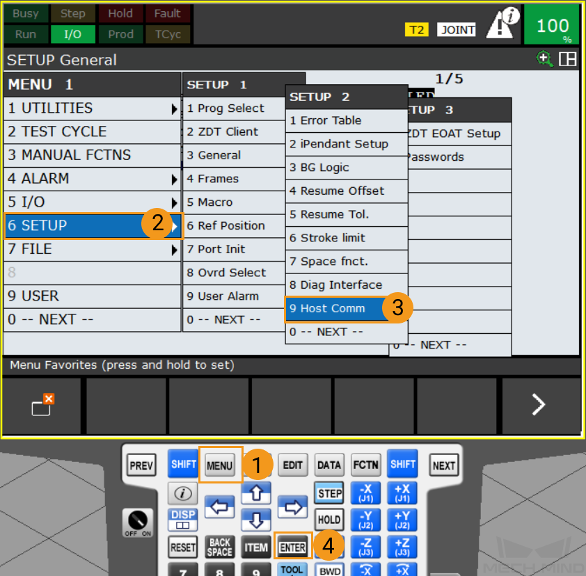
IP Configuration
-
Press to open the SETUP Protocols window.
-
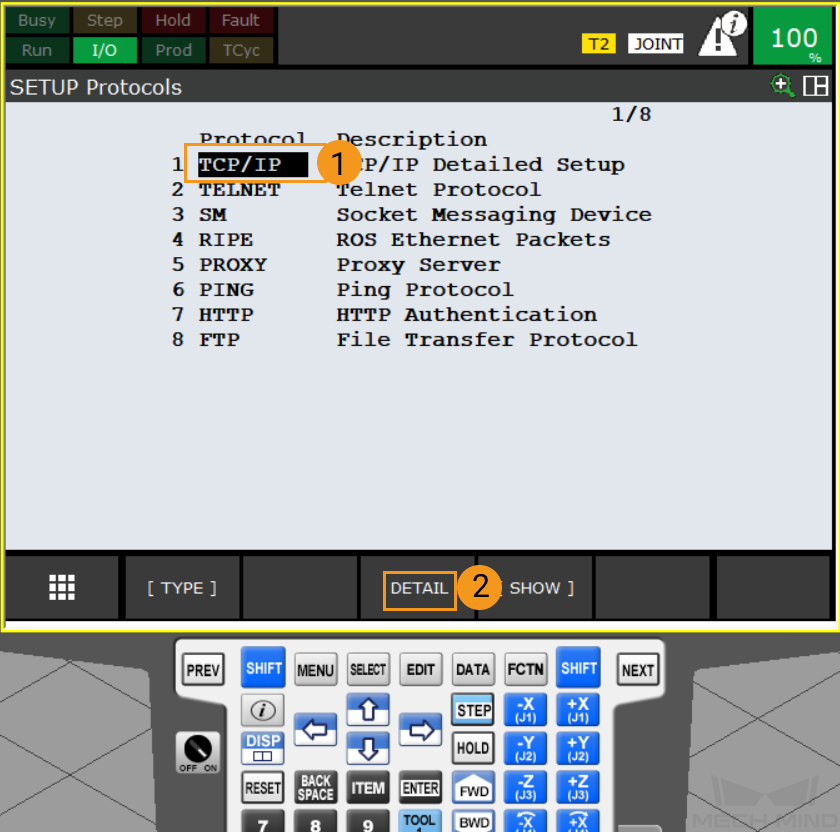
Select TCP/IP and press DETAIL to open the SETUP Host Comm window.
-
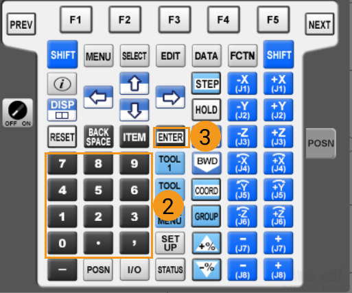
If the Ethernet cable is connected to CD38A port (Port#1), press the IP address line and enter the IP address by using the keyboard of the teach pendant, and then press
ENTERto finish. Please note that the robot IP address should be within the same subnet as that of the IPC.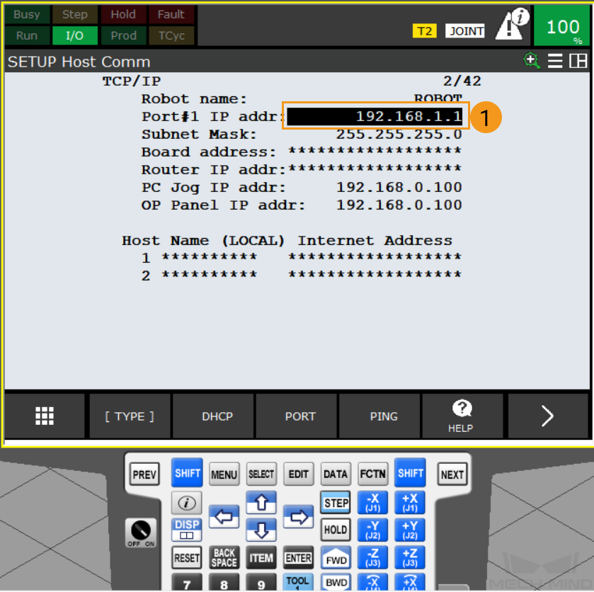
If the Ethernet cable is connected to CD38B port (Port#2), please press Port to switch to Port#2. Then you can enter the robot IP in the IP address line and press
ENTERon the teach pendant to finish.
Set up “Robot and Interface Configuration” in Mech-Vision
-
Click Robot and Interface Configuration in the toolbar of Mech-Vision.
-
Select Listed robot from the Select robot drop-down menu, and then click Select robot model. Select the FANUC robot model that you use, and then click Next.
-
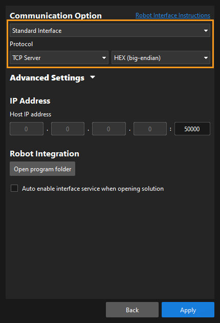
In Communication Option, select Standard Interface for Interface Type, TCP Server and HEX-Big endian for Protocol, and then click Apply.
-
Make sure the Interface Service is started: on the toolbar of Mech-Vision, the Interface Service switch on the far right is flipped and turned to blue.

Load the Program Files
Back up Robot Programs
-
Connect the USB flash drive, and press to open the FILE window.
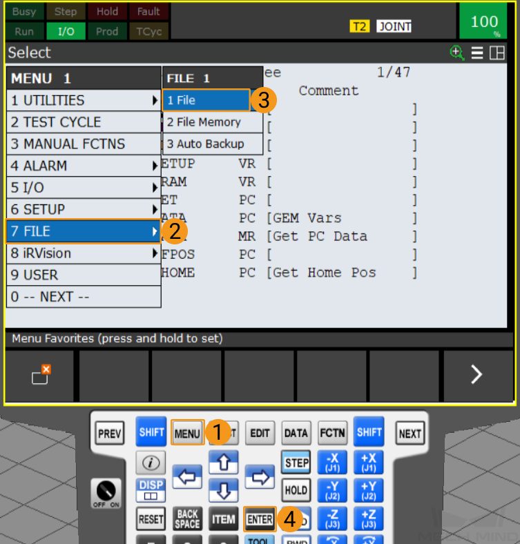
You can connect the flash drive to the robot controller or the teach pendant according to the actual requirement. -
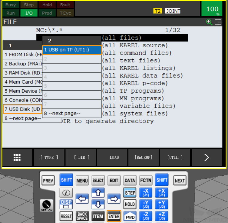
Select to select the flash drive folder, and press on
ENTERto open the USB folder. If your flash drive is connected to the controller, please select USB Disk (UD1:); if your USB flash drive is connected to the teach pendant, please select USB on TP (UT1:).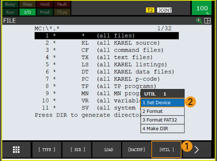
-
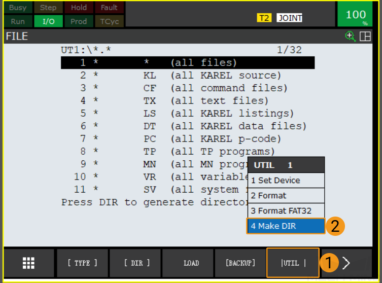
In the USB FILE window, select to create a new folder.
-
Select Words, Upper Case, Lower Case, or Options/Keybd to name the folder, and then press on
ENTERto confirm and enter the new folder. In this example, Upper Case is selected, and the folder name is AOA.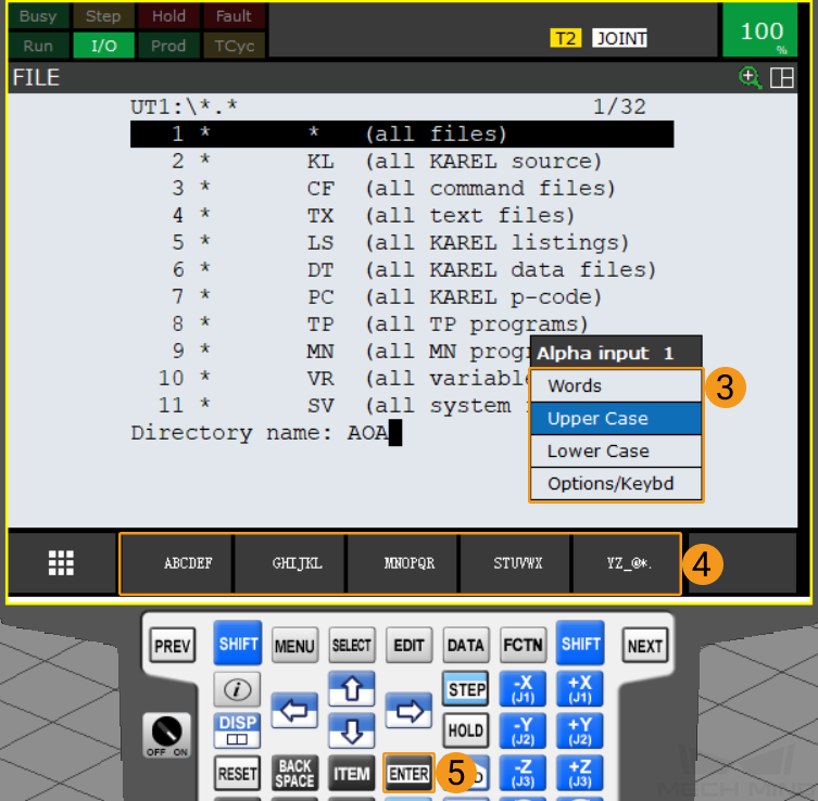
-
Select to backup the files.
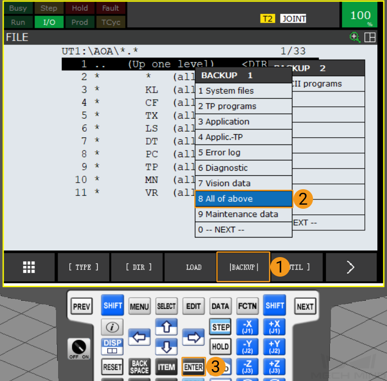
-
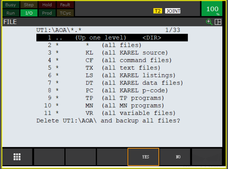
A message asking whether to delete the new folder before backup files will display on the screen. Select
Yes. Then a message asking whether to delete the new folder and backup all files will display on the screen. SelectYesto start the backup.
-
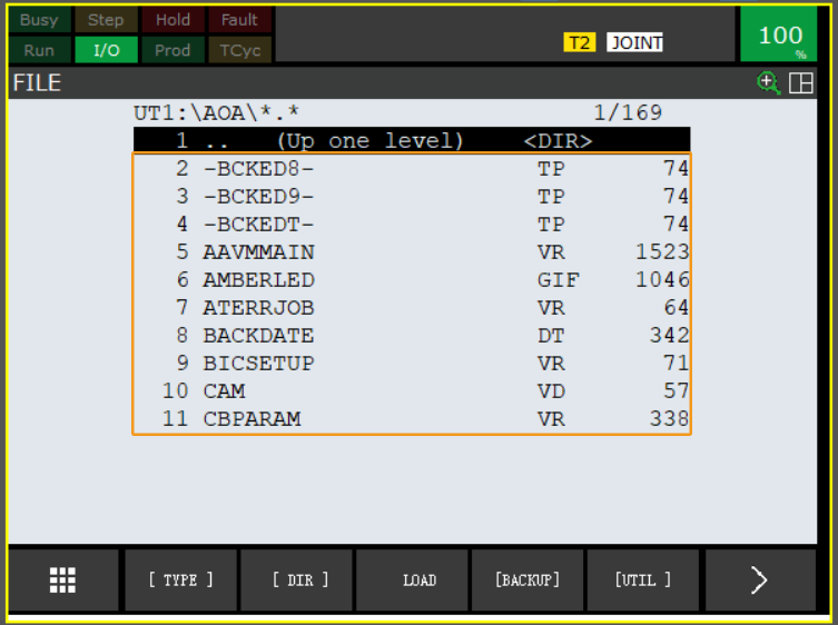
After the backup is complete, press to view all backup files.
Prepare the Files
Navigate to Mech-Center/Robot_Interface from the installation directory of Mech-Mind Software Suite, and copy the entire FANUC folder to the root directory of your flash drive.
Load the Files to the Robot
-
Connect the USB flash drive, and press to open the FILE window.

You can connect the flash drive to the robot controller or the teach pendant according to the actual requirement. -
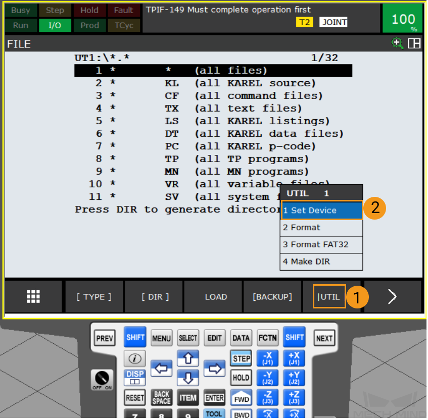
Press in turn.
-
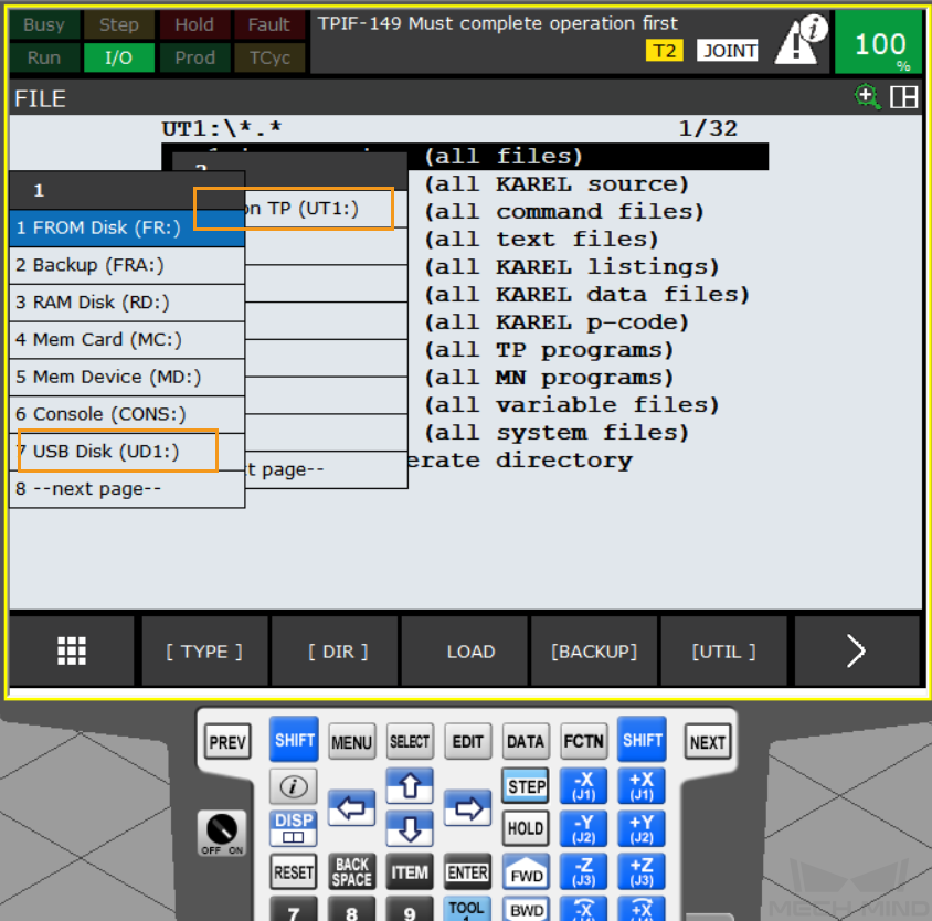
Select the USB flash drive. If your flash drive is connected to the controller, please select USB Disk (UD1:); if your USB flash drive is connected to the teach pendant, please select USB on TP (UT1:).
-
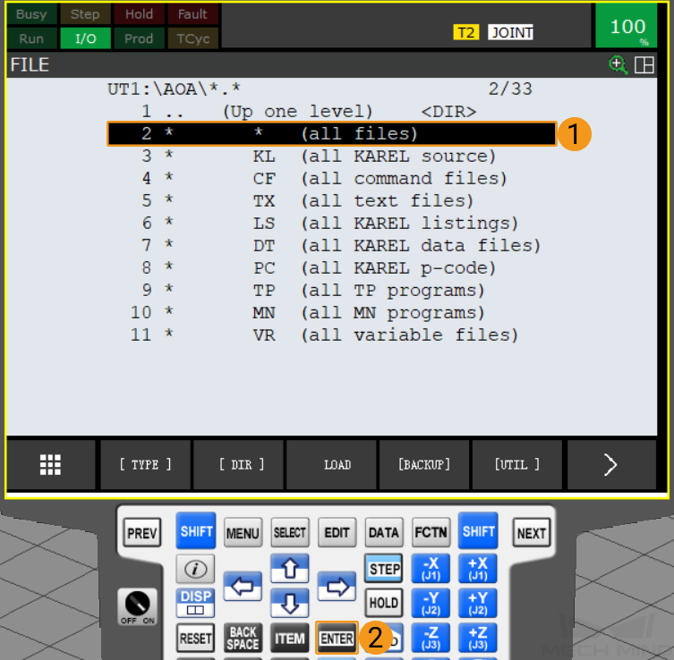
After confirming the install location, you can view the files in the root directory of the flash drive. Select the first line (all files) and press
ENTERto enter the root directory of the USB flash drive.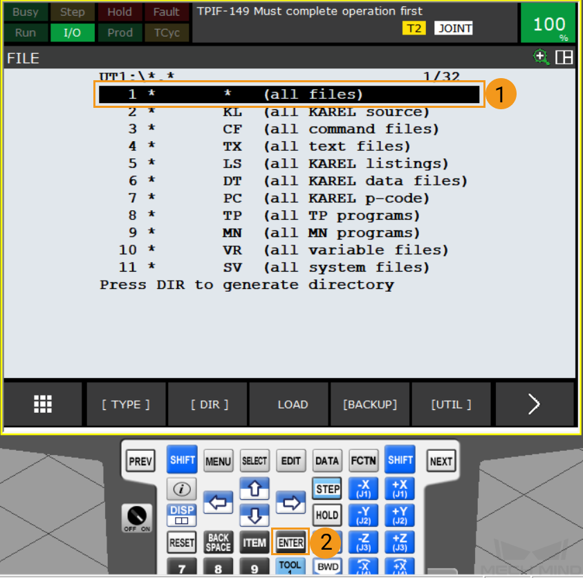
-
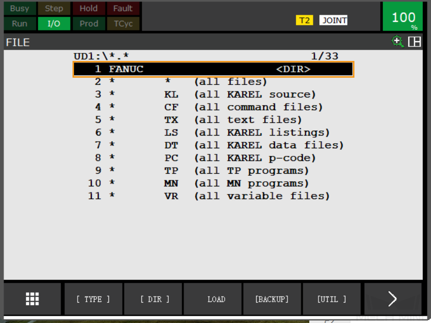
In the root directory of the USB flash drive, select FANUC.
-
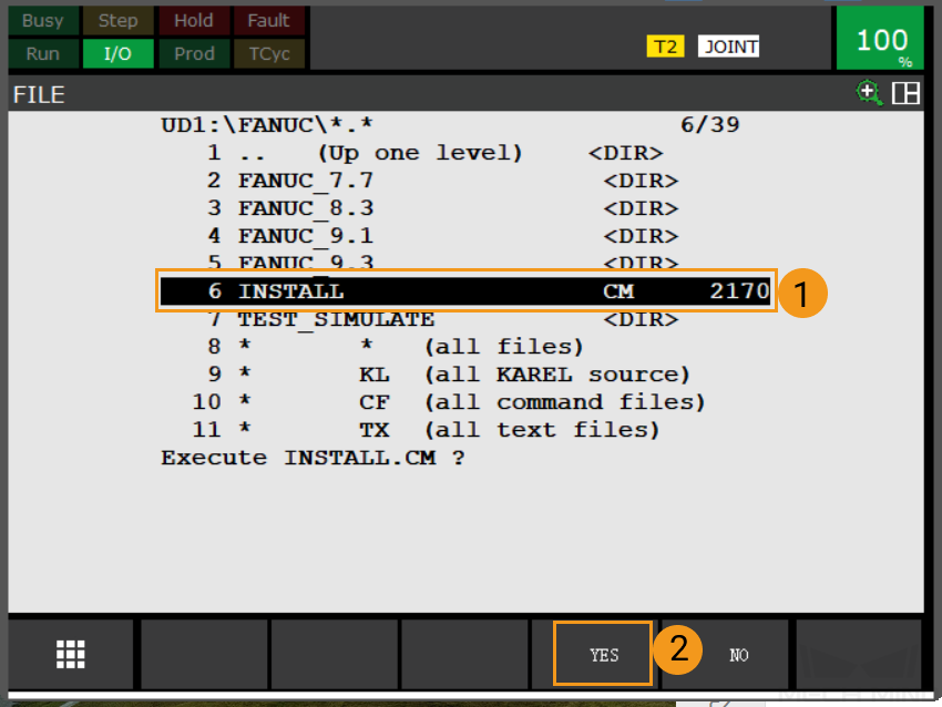
In the FANUC directory, select INSTALL and choose YES to start loading the programs.
-
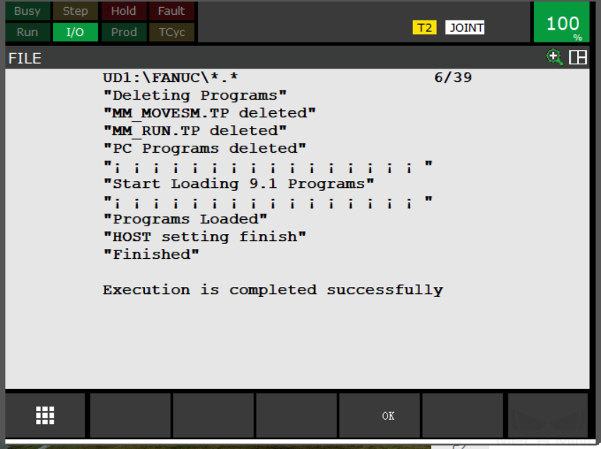
When the message “Programs Loaded” is displayed, the program files have been loaded successfully. Press OK to exit the program.
Further Configurations
-
After loading the program files, press
SELECTkey on the teach pendant to enter the program selection interface. Select MM_AUTO_CALIB and then pressENTERto open the program.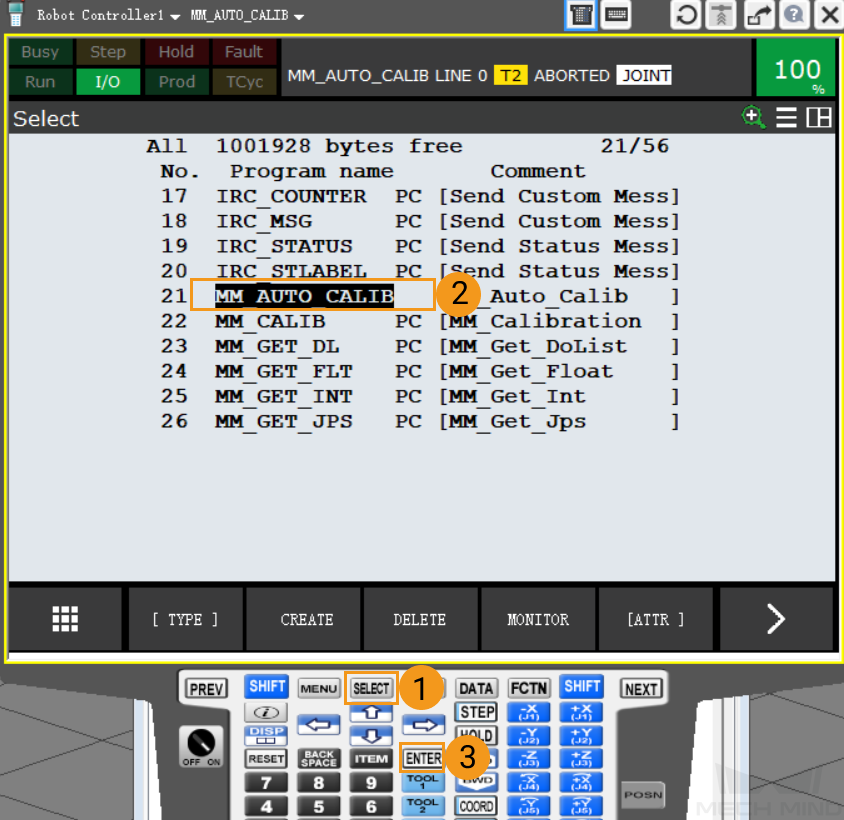
-
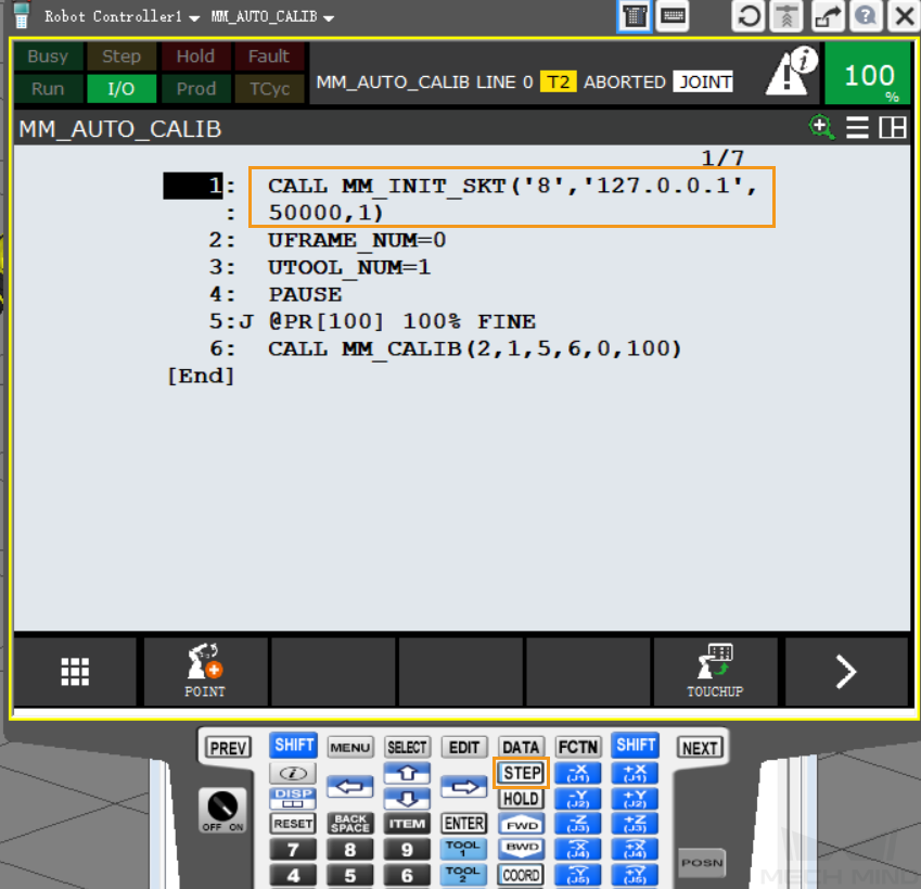
Configure the arguments of MM_INIT_SKT. There are 4 arguments in total. Please configure them according to your actual situation.
-
Argument 1: client port number (string 1-8)
-
Argument 2: IP address of the IPC
-
Argument 3: server port number of the IPC
-
Argument 4: timeout (min)
-
-
Then, press
STEPkey to switch into Step mode. Now the Step icon on the teach pendant turns yellow as shown below.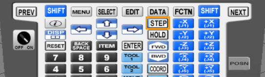

-
Press and hold either one of the deadman switches on the back of the teach pendant.

-
Press the
SHIFTandFWDkeys at the same time to call MM_INIT_SKT.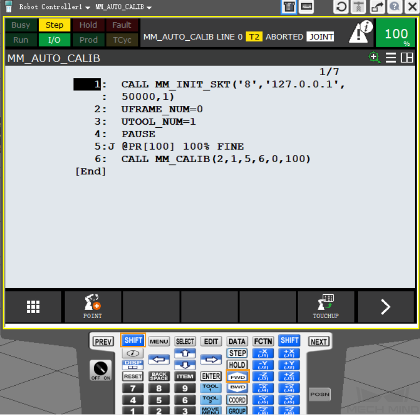
-
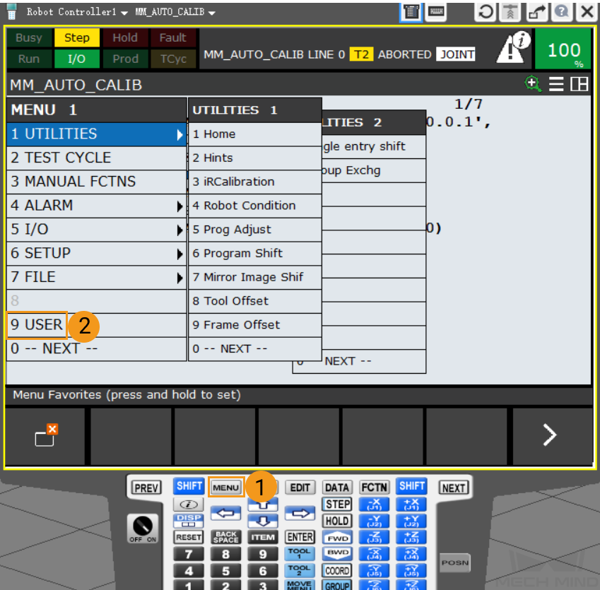
After calling MM_INIT_SKT, press MENU > USER to enter the USER interface.
-
If the following information appears in the interface, the loading is successful. In this case, restart the robot.
If the following information appears in the interface, restart the robot. 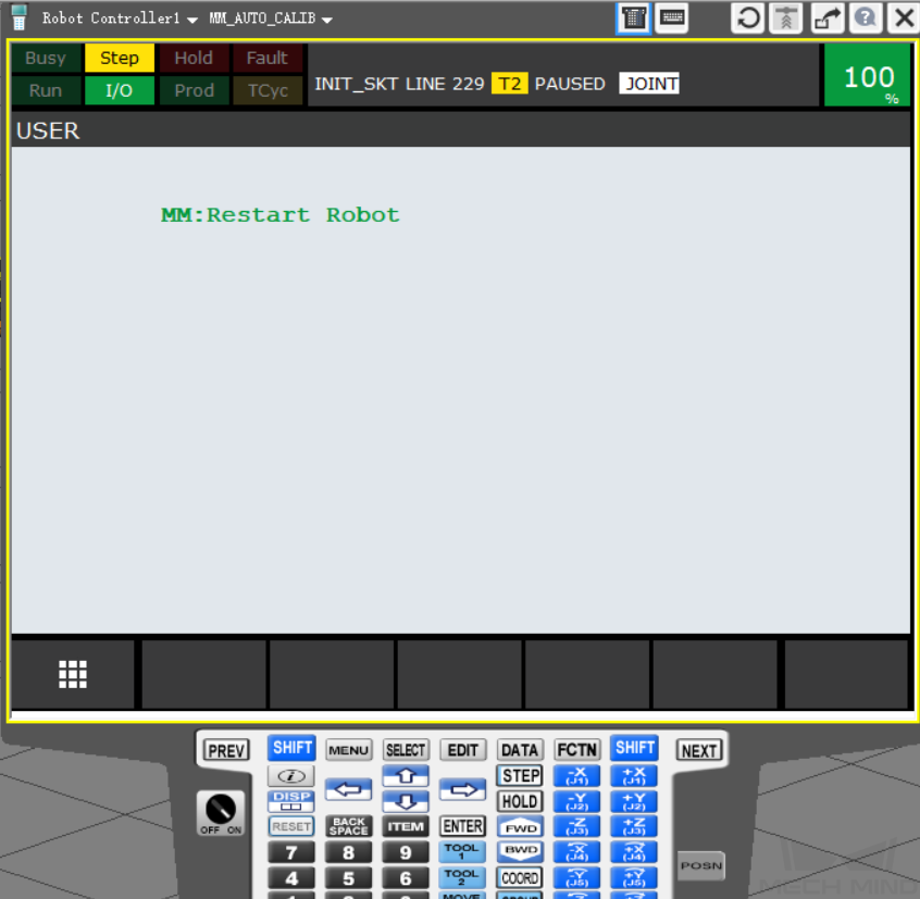
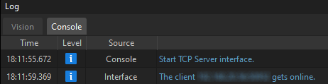
Test Robot Connection
Run the first command MM_INIT_SKT of the program MM_AUTO_CALIB again according to the instructions mentioned before. The robot can be connected successfully if the Console tab of Mech-Vision Log panel displays messages indicating that the client is connected.