Communication Configuration and Example Program Usage
This topic introduces the commands for Modbus TCP communication between a Siemens SIMATIC S7 PLC using the TIA Portal software and Mech-Mind Software Suite.
Hardware and Software Requirements
Hardware
-
Siemens SIMATIC S7-1200, CPU 1211C, DC/DC/DC
-
AC 220 V to DC 24 V power adapter
-
Mech-Mind Vision System IPC
-
Ethernet cables
Software
-
Siemens TIA Portal V15.1
-
Mech-Mind Software Suite: 1.7.0 or above
-
PLC Example Programs:
-
MM Modbus TCP.scl (for establishing Modbus TCP communication);
-
MM Modbus TCP Interface Program.scl (for implementing the functions of various interface commands)
The example files are stored in
Mech-Center/Robot_Interface/Modbus TCP/Siemens TIA Portalin the installation directory of Mech-Mind Software Suite. Please copy the example file to the computer on which the TIA Portal is installed. -
| The firewall on the IPC must be turned off. |
Configure IPC and Initiate Communication
Set the IPv4 Address of the IPC
-
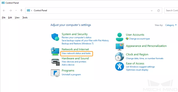
Open the Control Panel, and click View network status and tasks.
-
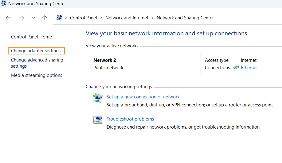
In the “Network and Sharing Center” window, click Change adapter settings.
-
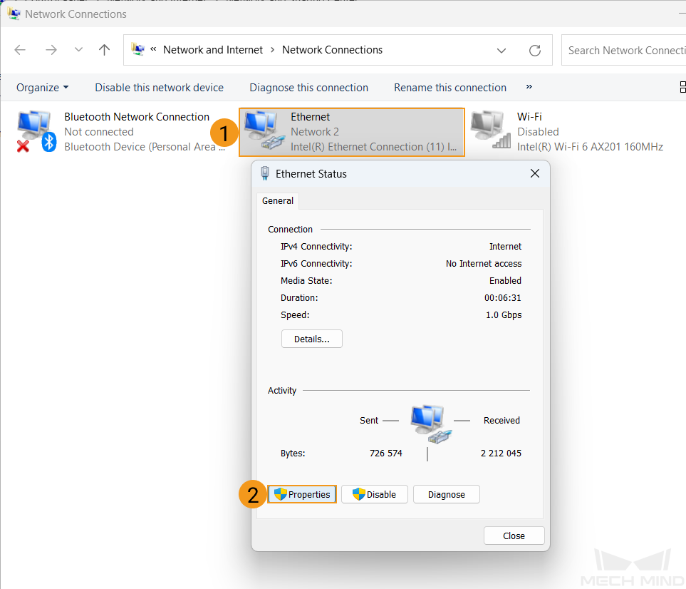
In the “Network Connections” window, double-click the Ethernet interface connected to the PLC, and select Properties in the pop-up Ethernet Status window.
-
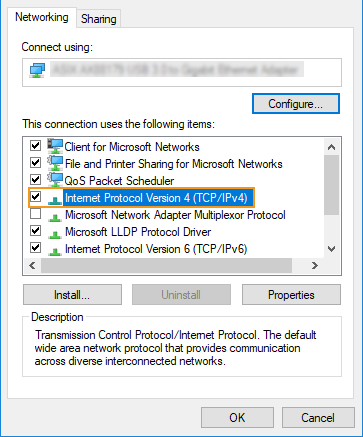
In the Ethernet Properties window, select Networking in the menu bar, and double-click Internet Protocol Version 4(TCP/IPv4).
-
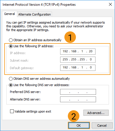
In the Internet Protocol Version 4 (TCP/IPv4) window, select “Use the following IP address”, and set the IP address, subnet mask and default gateway (must be in the same subnet as the PLC). Then, click “OK” to save the changes.
Set up “Robot and Interface Configuration” in Mech-Vision
-
Click Robot and Interface Configuration on the toolbar of Mech-Vision.
-
Select Listed robot from the Select robot drop-down menu, and then click Select robot model. Select the robot model that you use, and then click Next.
-
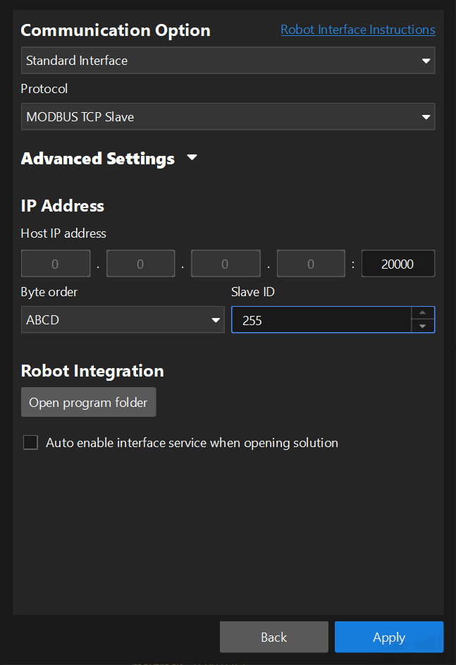
In the Communication Option panel, follow the steps below to proceed:
-
Interface Type: Standard Interface
-
Protocol: Modbus TCP SLAVE
-
Port number of Host IP address: according to your needs (set to 2000 here)
-
Byte order: ABCD
-
Slave ID: according to your needs (set to 255 here)
-
Click Apply.
-
-
Make sure the Interface Service is started: In the toolbar of Mech-Vision, the Interface Service switch on the far right is flipped and turned to blue.

Create and Configure the PLC Project
Create PLC Project
| If needed, click Save project to save the changes to the project. |
-
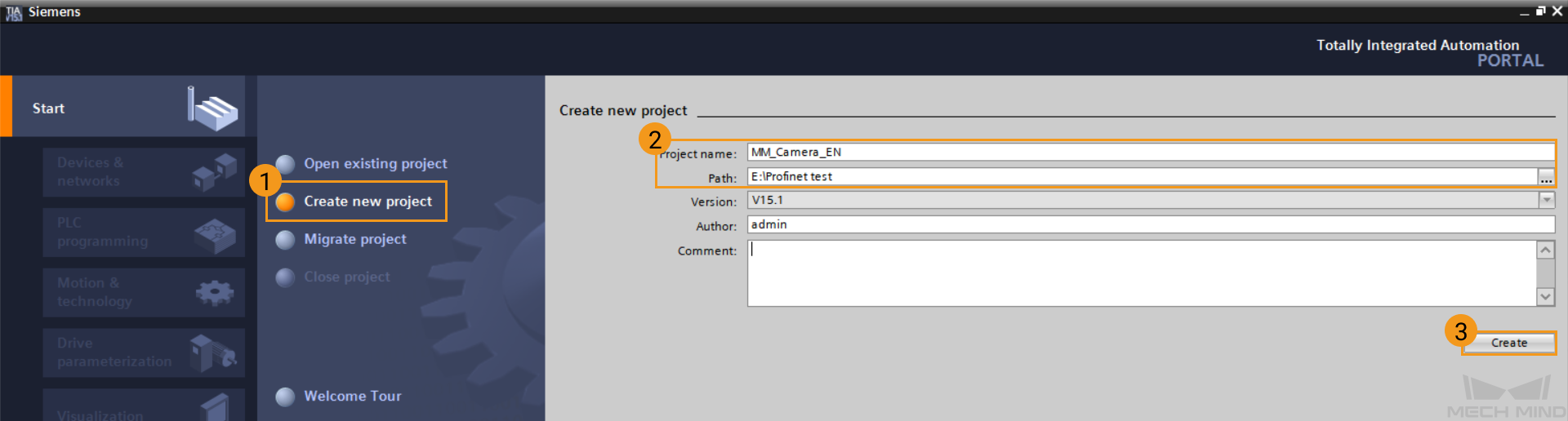
Open TIA Portal and click Create new project. Input “Project name” and “Path”, and click Create. Click in the pop-up page.
-
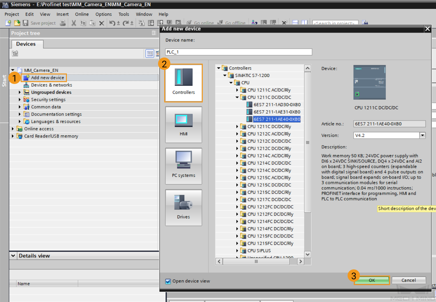
In the Project tree panel, double-click Add new device. In the new window, click Controllers, and find the CPU module that you are using, and input the name in the blank box under “Device name”. Click OK to confirm adding the device. Here, the device is named PLC_1.
-
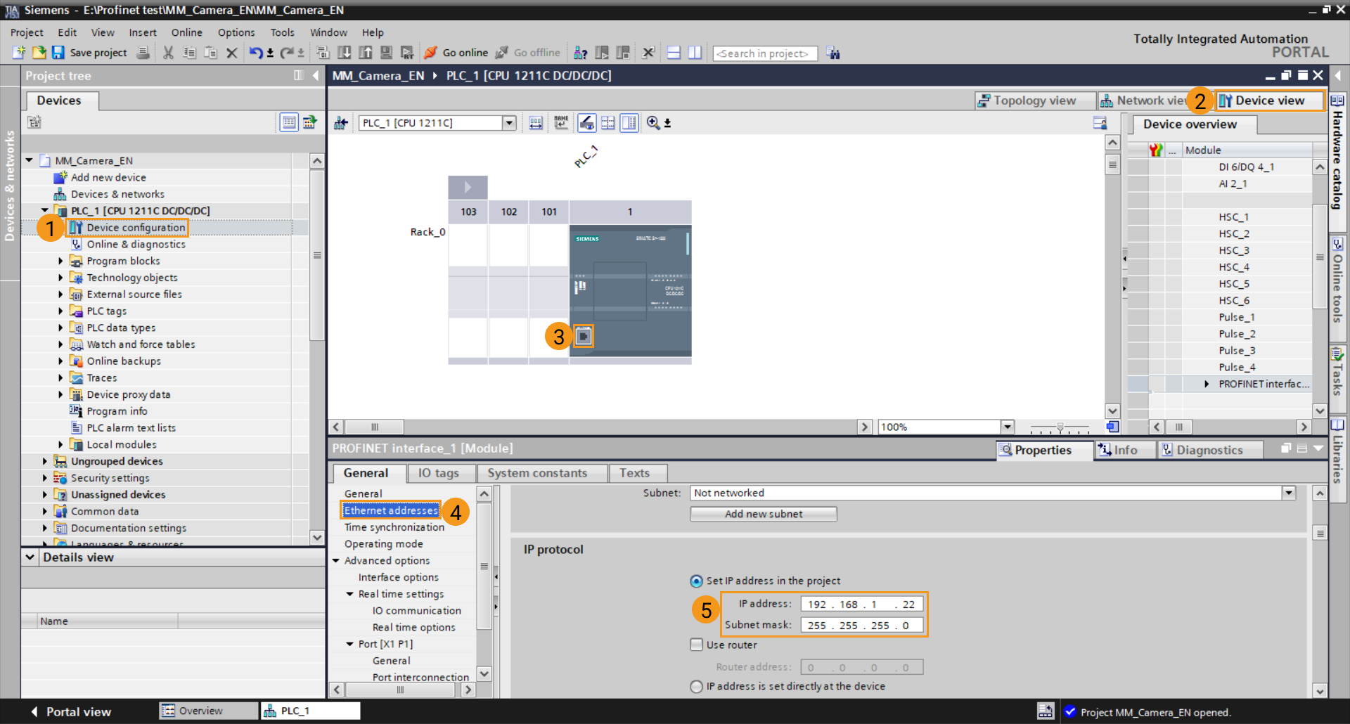
Select Device configuration under PLC_1 in the Project tree panel, and then click Device view tab on the right. In this tab, double-click ethernet icon in PLC_1. Down in the Properties ‣ General tab, click Ethernet addresses to set the IP address of the PLC. Use the default value for Subnet mask.
Import Mech-Mind Example Programs
| Before you add the example program to a project already in use, it is recommended to import it to a new project and test it first. In the following steps, the project created earlier is used to import and test the example program. |
-
In the Project tree panel, double-click PLC_1[CPU 1211C DC/DC/DC] ‣ External source files, and then double-click Add new external file. In the pop-up window, locate and select the
MM Modbus TCP.sclandMM Modbus TCP Interface Program.sclfiles. Click Open to import these files.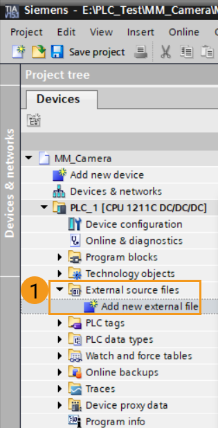
-
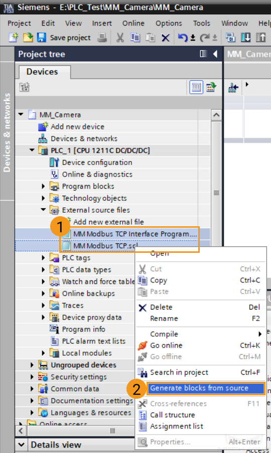
Select MM Modbus TCP.scl first, and then select MM Modbus TCP Interface Program.scl. Next, and right-click these files. In the right-click menu, select Generate blocks from source.
-
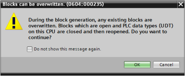
If the warning message saying Blocks can be overwritten pops up, click OK.
-
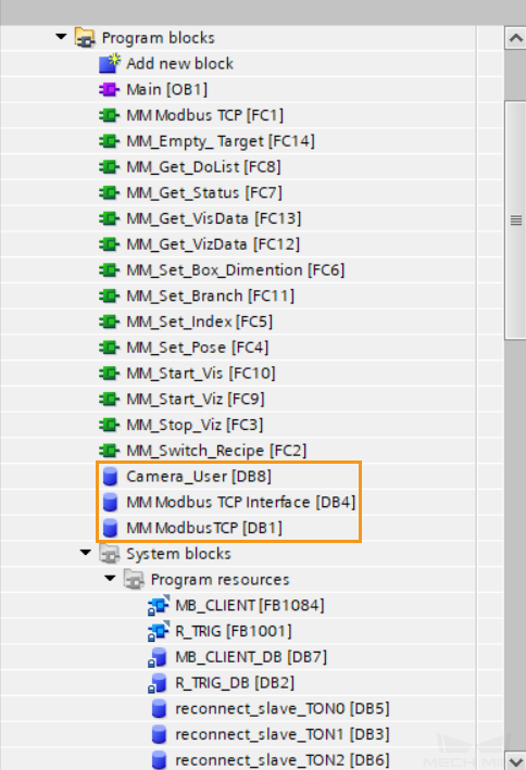
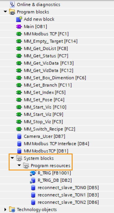
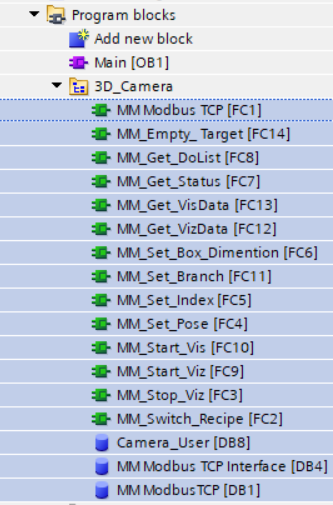
The functions and data blocks generated from these external source files are shown below. In terms of the function of the data blocks, Camera_User DB stores user data, MM Modbus TCP Interface stores communication data, and MM Modbus TCP stores communication configuration parameters.
-
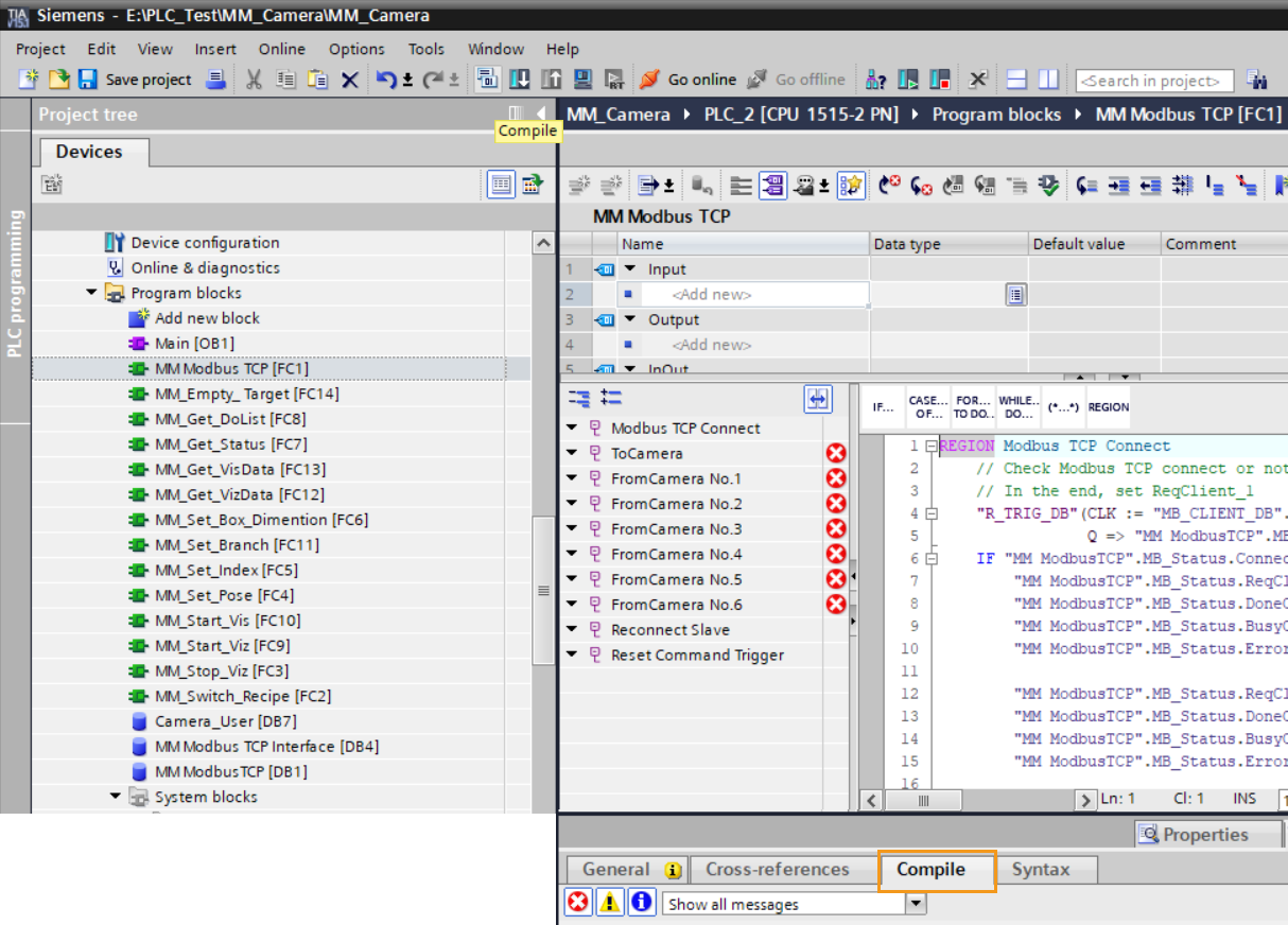
Double-click the MM Modbus TCP function block. Then, click the ToCamera and the FromCamera network No.1~6 sequentially to check that the DB number in the MB_DATA_PTR variable is the same as that of the MM Modbus TCP Interface data block. In this case, the number is 2 as shown in the picture below.
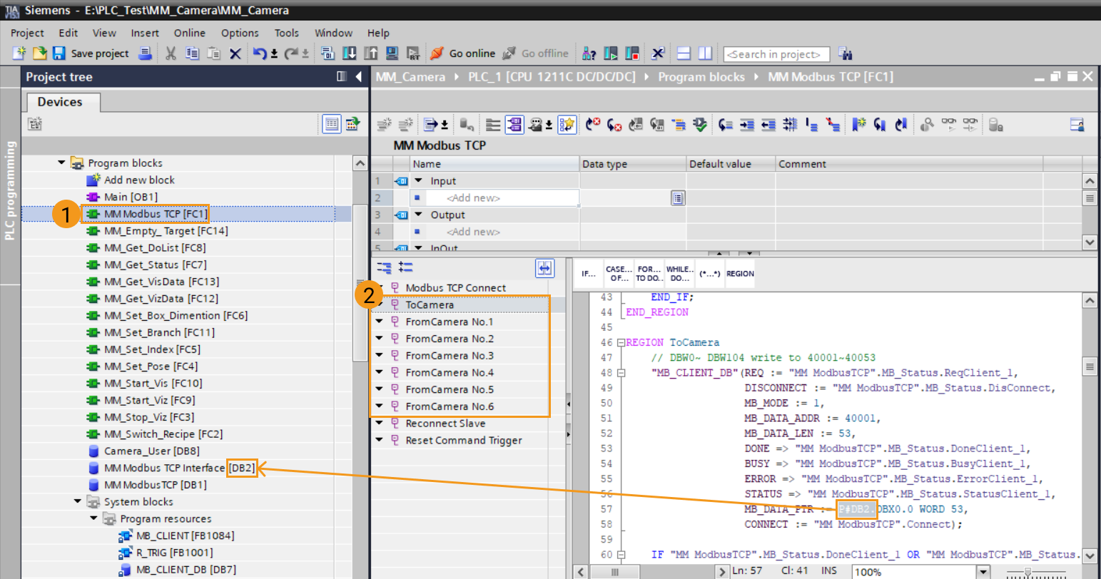
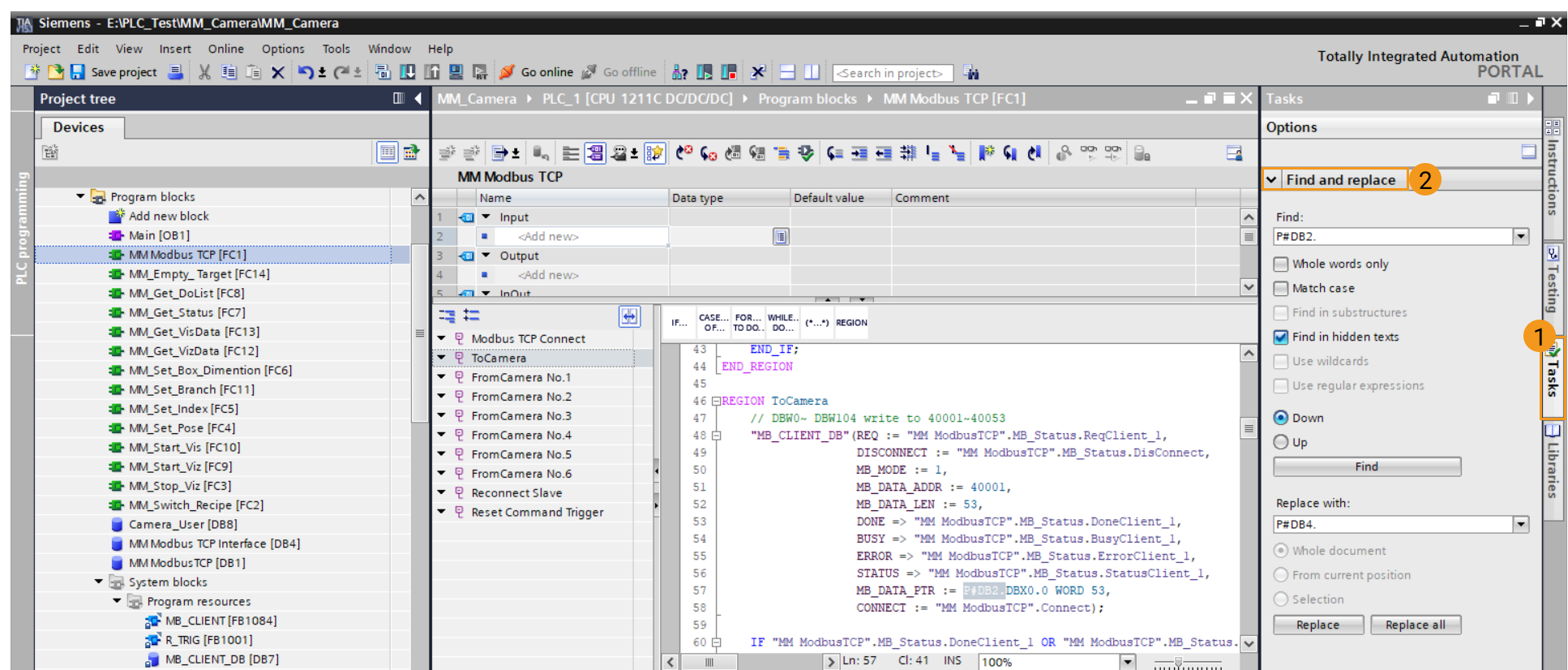
If the DB number in the MB_DATA_PTR variable does not match the number of the MM Modbus TCP Interface DB, and it is not feasible to change the number of the MM Modbus TCP Interface DB, you can utilize the “Find and replace” function in the Options panel to change the DB in the MB_DATA_PTR variable to the DB number used by MM Modbus TCP Interface.
-
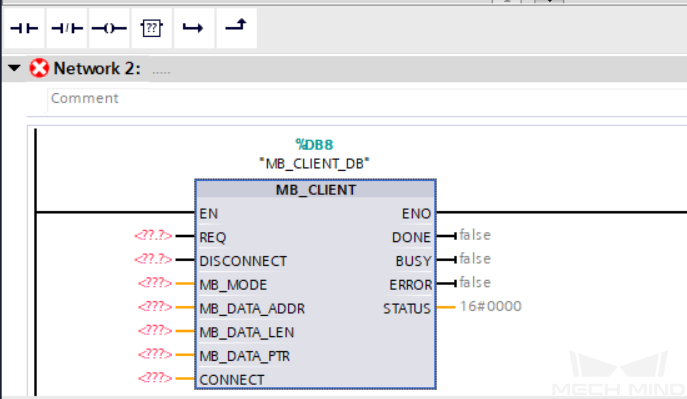
In the Project tree panel, navigate to PLC_1 ‣ Program blocks ‣ System blocks ‣ Program resources, check if the MB_CLIENT function block and MB_CLIENT_DB data block are automatically generated. If not, refer to the following step to generate the MB_CLIENT FB suitable for the current CPU. If so, skip the next step.
-
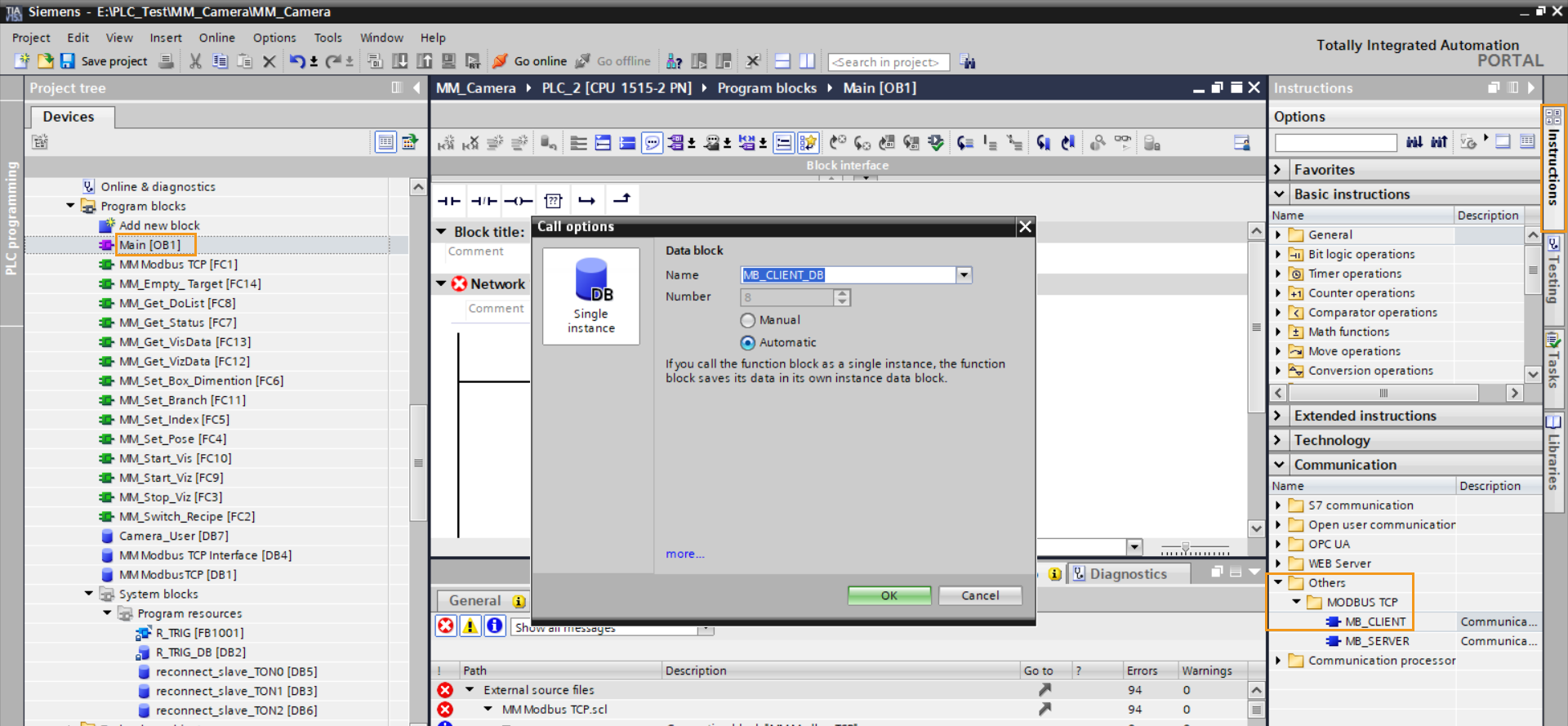
In the Project tree panel, click Program blocks, and double click Main[OB1]. Select the diagram under any of the networks, and then select the Instructions tab to the right. Navigate to , and double-click the MB_CLIENT block. In the pop-up Call options window, click OK.
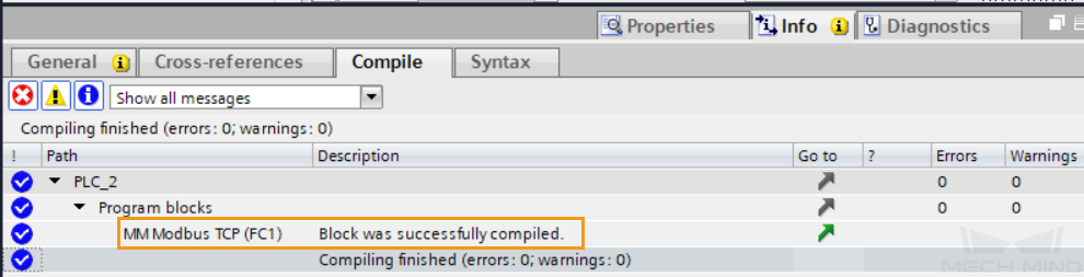
In the Project tree panel, navigate to Program blocks ‣ System blocks. The MB_CLIENT FB and MB_CLIENT_DB DB should be generated now. Return to the MM Modbus TCP FC, and click the Compile tab on the toolbar.
When the following messages are displayed in the Compile tab under the “Info” tab at the bottom, you can delete the MB_CLIENT block under Main[OB1] Network 1 in the Main OB.
-
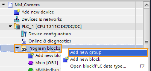
To ease the management and maintenance later on, create a new group under Program blocks to organize the blocks: In the Project tree panel, under PLC_1, right-click Program blocks and select Add new group. Here, the new group is named 3D_Camera.
-
Select all the FCs and DBs generated from the external source files and drag these blocks into the 3D_Camera group.
Build Program and Download to PLC
-
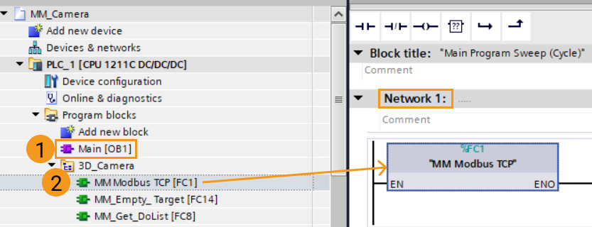
In the Project tree panel, navigate to Program blocks, and double-click Main OB to open it. Then, Drag the MM Modbus TCP FC to Network 1 in the Main OB.
-
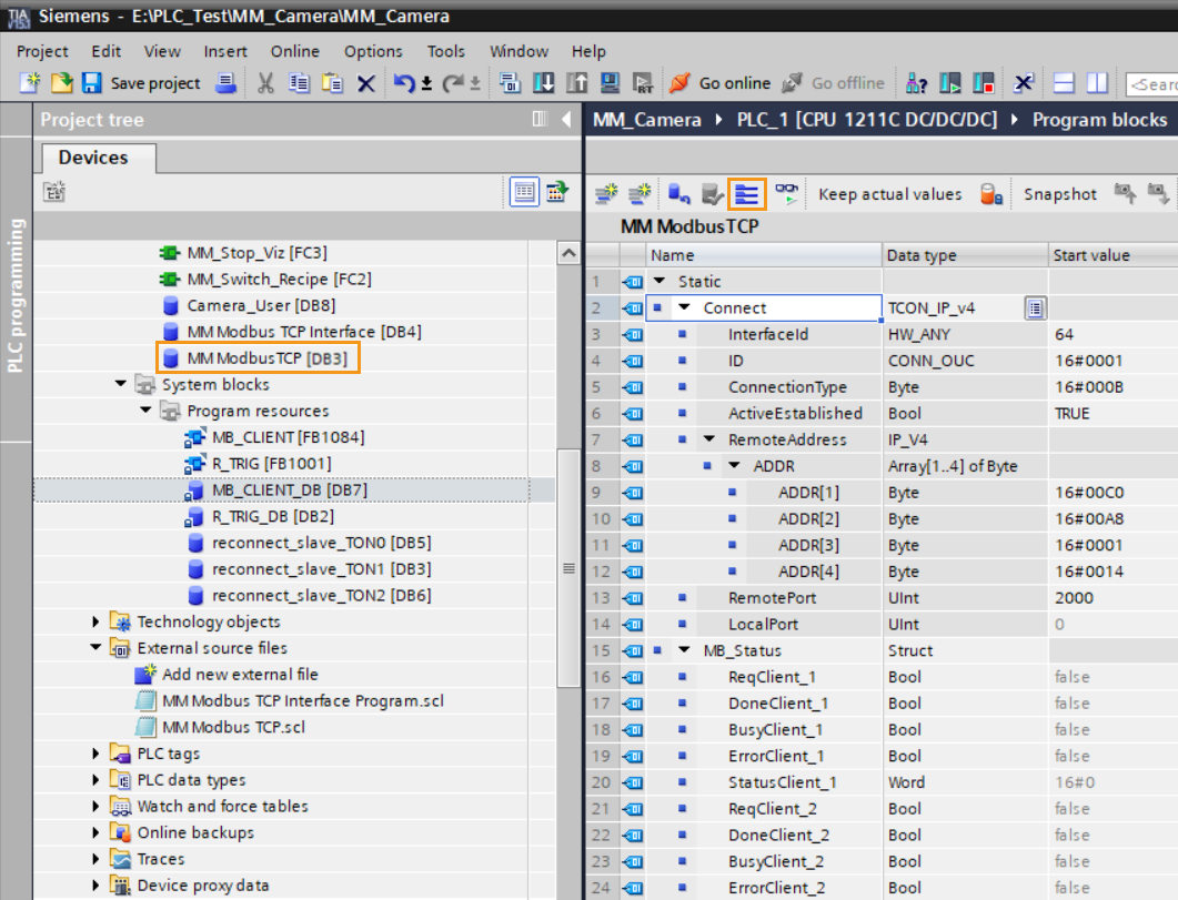
Double-click the MM ModbusTCP DB to open it, and then click the expand icon. Under RemoteAddress, check if the 4 hexadecimal numbers in ADDR match the segments of the IP address of the IPC (which is 192.168.1.20 in this example), and if the number in RemotePort matches the port number set in Mech-Vision (which is 2000 in this example).
-
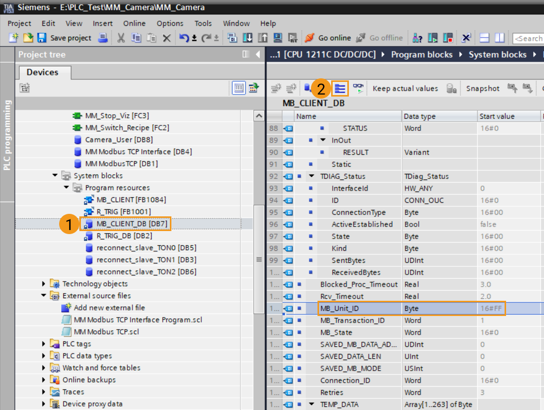
Navigate to , double-click the MB_CLIENT_DB DB to open it, and then click the expand icon. Under Static ‣ TDIAG_Status, check if the hexadecimal number in MB_Unit_ID matches the Slave ID set in Mech-Vision (which is 255 in this example).
-
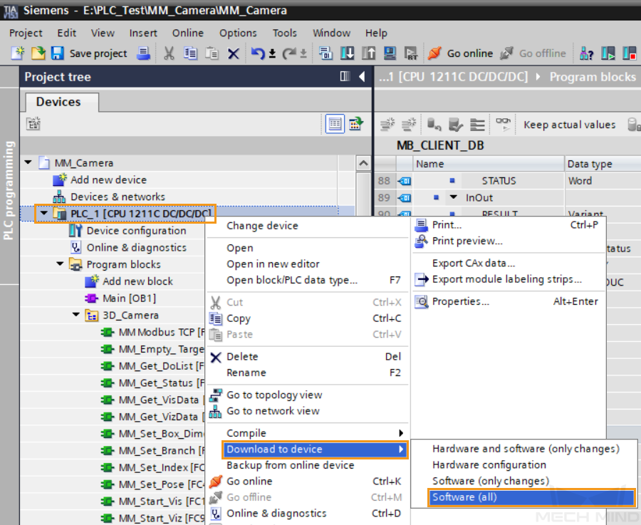
In the Program tree panel, right-click PLC_1, and select .
-
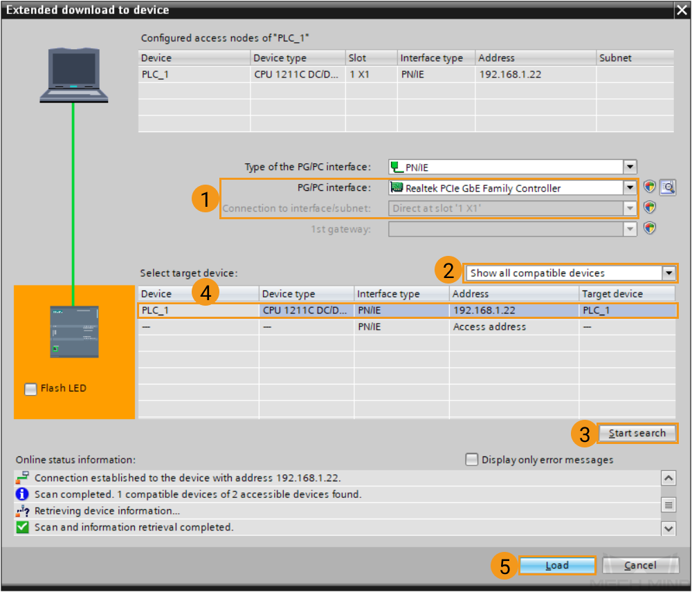
In the pop-up Extended download to device window, make the following selections: Select the interface connected to the PLC for PG/PC interface. Select Direct at slot ‘1 X1’ for Connection to interface/subnet. Select Show all compatible devices for Select target device. Then, click Start search. Select the corresponding device in the search result, and then click Load.
-
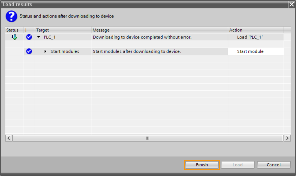
In the pop-up Load results window, click Finish once the download is completed.
Check Communication
-
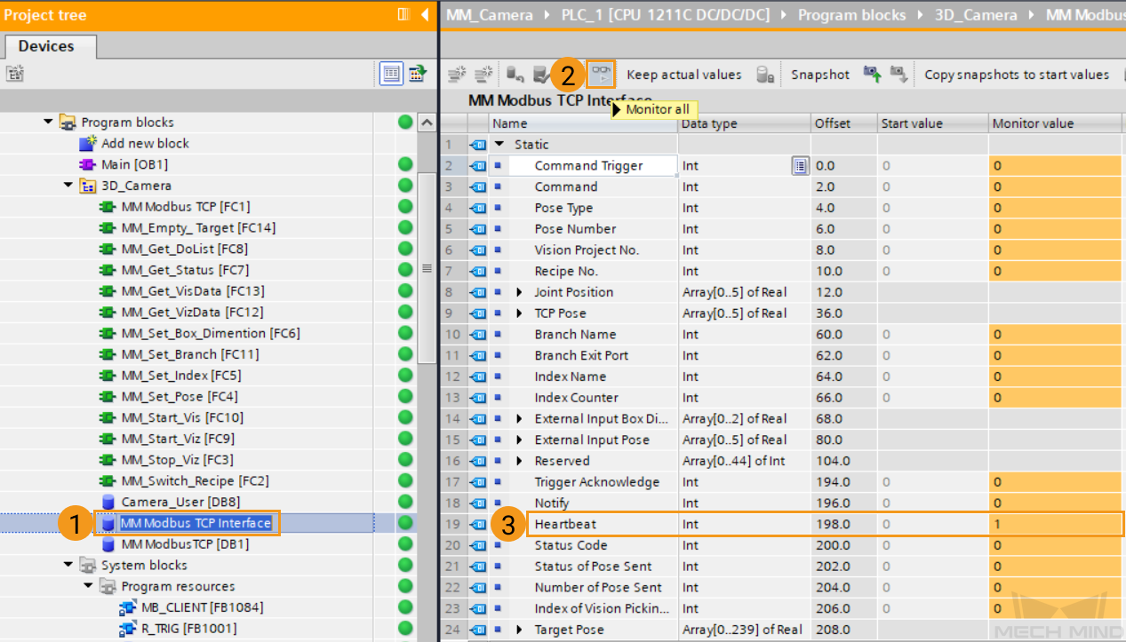
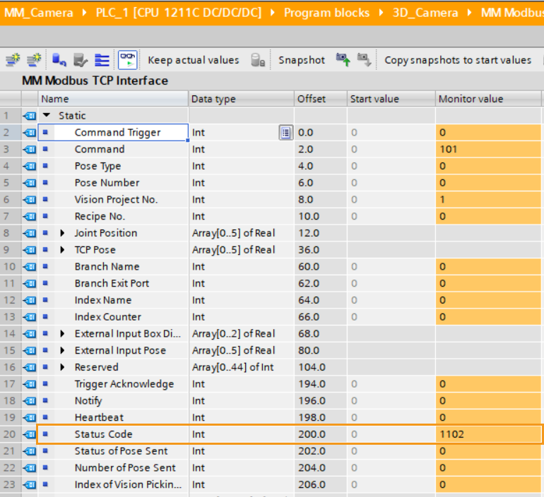
In the Program tree panel, double-click the MM Modbus TCP Interface DB, and then click the monitor icon. If the monitor value of Heartbeat keeps changing, the connection is successfully established.
-
The PLC is successfully connected if the following message is displayed in the Console tab of Mech-Vision Log panel: client connected. If you don’t see this log message, check if:
-
The hardware is properly connected;
-
The Interface Service has been started successfully in Mech-Vision;
-
The PLC program has been successfully downloaded to the PLC.
-
Test with Vision Projects
This section introduces how to use the example program function block to trigger the Mech-Vision project to obtain vision points and trigger the Mech-Viz project to obtain the planned path.
Prerequisites
-
Create a Mech-Vision solution. In the project list, right-click the solution and select Autoload Solution. Projects in the solution are also auto-loaded and the specific project number will appear in front of the project name.
-
Create a Mech-Viz project. Right-click the project name in Resources in Mech-Viz and select Autoload Project.
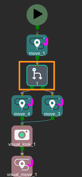
The Mech-Viz project used for testing contains a “Branch by Msg” Step that has been renamed to 1 as shown below.
Test with Mech-Vision Project
Configure PLC Program
-
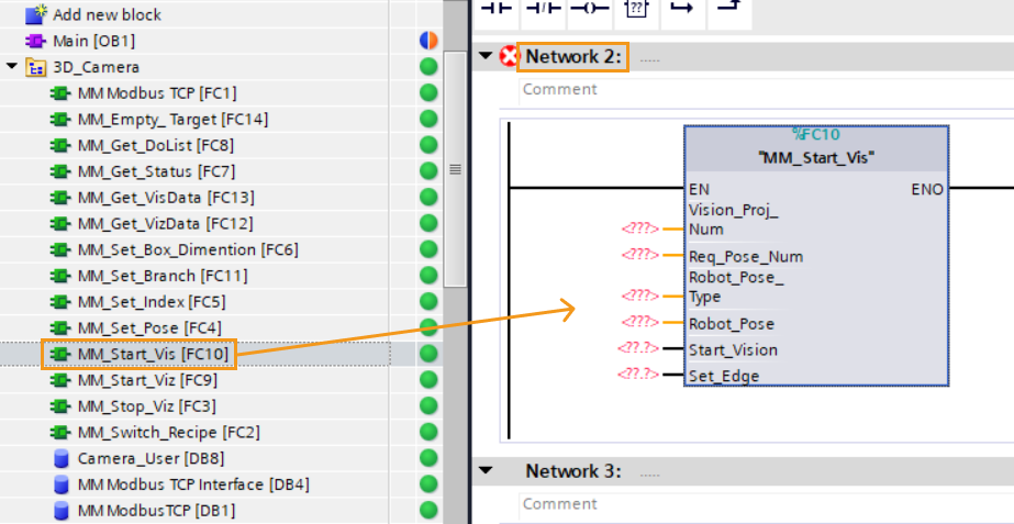
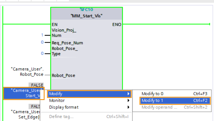
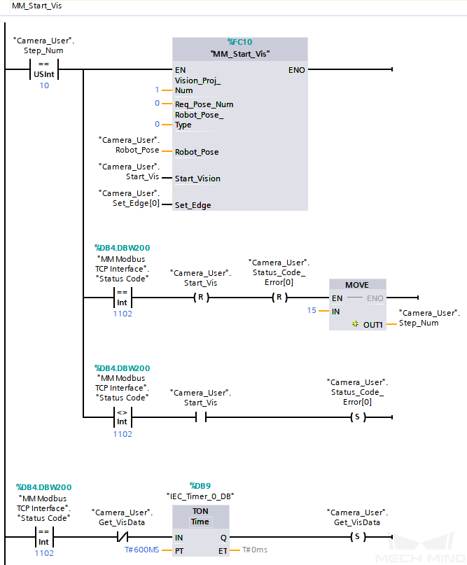
In the Project tree panel, navigate to Program blocks, double-click the Main OB to open it. Then, Drag the MM_Start_Vis FC to Network 2 in the Main OB.
-
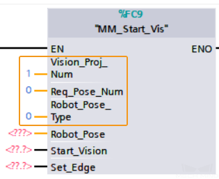
Set Mech-Vision project ID, namely, the number before the project name in the project list in Mech-Vision. For example, set the value of Vision_Proj_Num to 1, then project No.1 in Mech-Vision will be started.
-
Set the number of vision points to be sent by Mech-Vision: change the value of the Req_Pose_Num port. If the value is set to 0, the Mech-Vision project will send all the vision points.
-
Set the type of pose to be sent by the robot. Set the value of Robot_Pose_Type to 0, indicating that the project is in Eye-to-Hand mode, and the image-capturing pose is not needed.
-
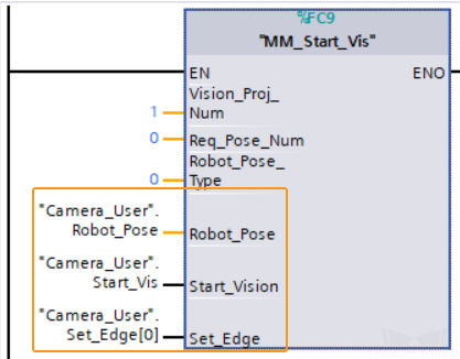
In the Project tree panel, navigate to Program blocks and click the Camera_User DB. From the Details view panel, drag the Robot_Pose, Start_Vision and Set_Edge parameters to the corresponding input ports of the MM_Start_Vis FC.
-
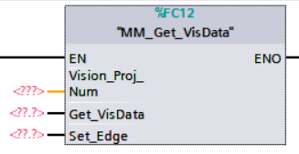
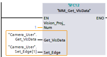
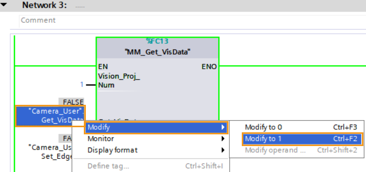
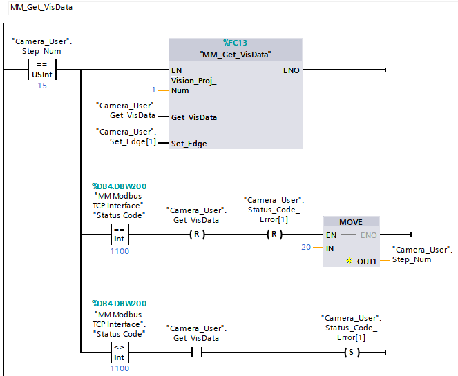
Drag the MM_Get_VisData FC to Network 3 in the Main OB.
-
Set Mech-Vision project ID, namely, the number before the project name in the project list in Mech-Vision. Set the port value of Vision_Proj_Num to 1, and the vision recognition result of Project No.1 in Mech-Vision will be obtained.
-
In the Project tree panel, navigate to Program blocks and click the Camera_User DB. From the Details view panel, drag the Get_VisData and Set_Edge parameters to the corresponding input ports of the MM_Get_VisData FC.
-
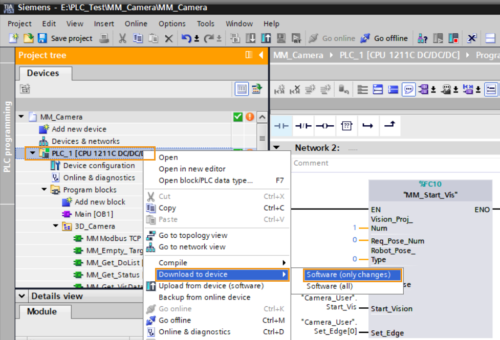
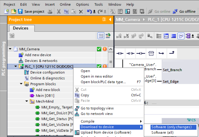
In the Program tree panel, right-click PLC_1, and select Download to device ‣ Software (only changes).
-
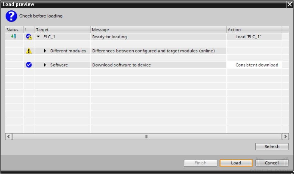
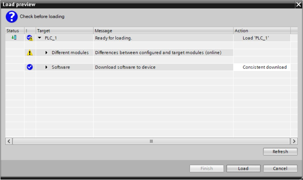
In the pop-up Load preview window, click Load to download the changes to the PLC.
Run Mech-Vision Project and Obtain Vision Points
-
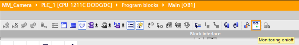
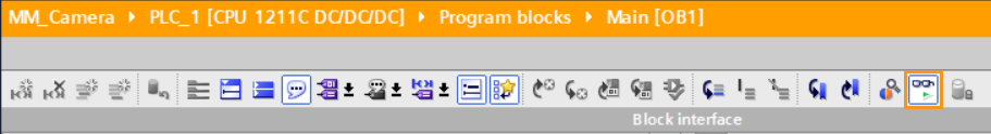
In the Main OB window, click the Monitoring on/off icon.
-
Start the Mech-Vision project: In Network 1, right-click the “Camera_User”.Start_Vis parameter in “MM_Start_Vis”, and select to 1. Then, reset the value of this parameter.
-
Check returned status code: Double-click the MM Modbus TCP Interface DB to open it, and check the monitor value of Status Code. 1102 represents that the project was started successfully. For other values, please refer to Status Codes and Troubleshooting for the corresponding error.
Obtain Vision Points from Mech-Vision
-
Right-click the “Camera_User”.Get_VisData parameter in “MM_Get_VisData”, and select . Then, reset the value of this parameter.
-
Check returned status code: Double-click the MM Modbus TCP Interface DB to open it, and check the monitor value of Status Code. 1100 represents that the vision point was received successfully. For other values, please refer to Status Codes and Troubleshooting for the corresponding error.
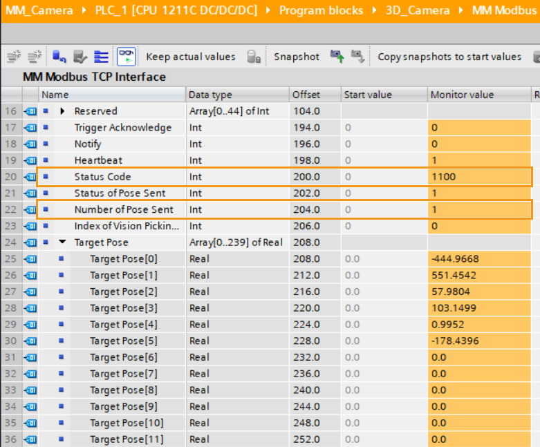
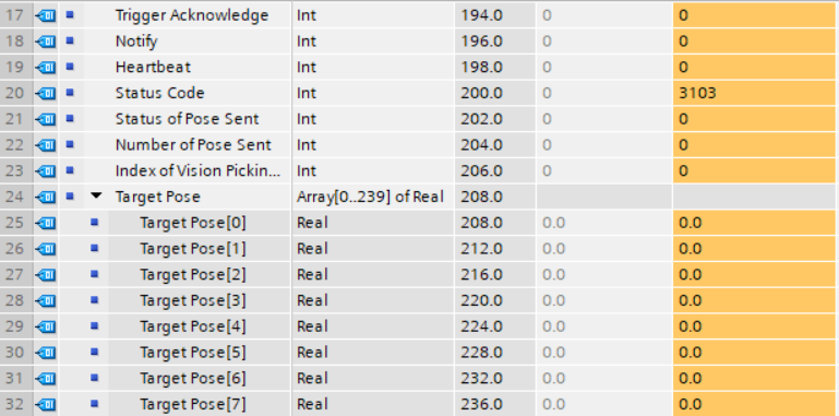
The value of “Number of Pose Sent” is 1, indicating that one pose is obtained. The poses are stored in “Target Pose”.
Test with Mech-Viz Project
Configure PLC Program
-
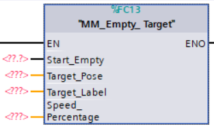
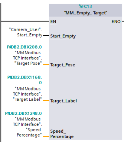
Drag the MM_Empty_Target FC to Network 4 in the Main OB.
-
Click the Camera_User and MM Modbus TCP Interface DB. From the Details view panel, drag the variables to the corresponding input ports of the “MM_Empty_Target” FC.
-
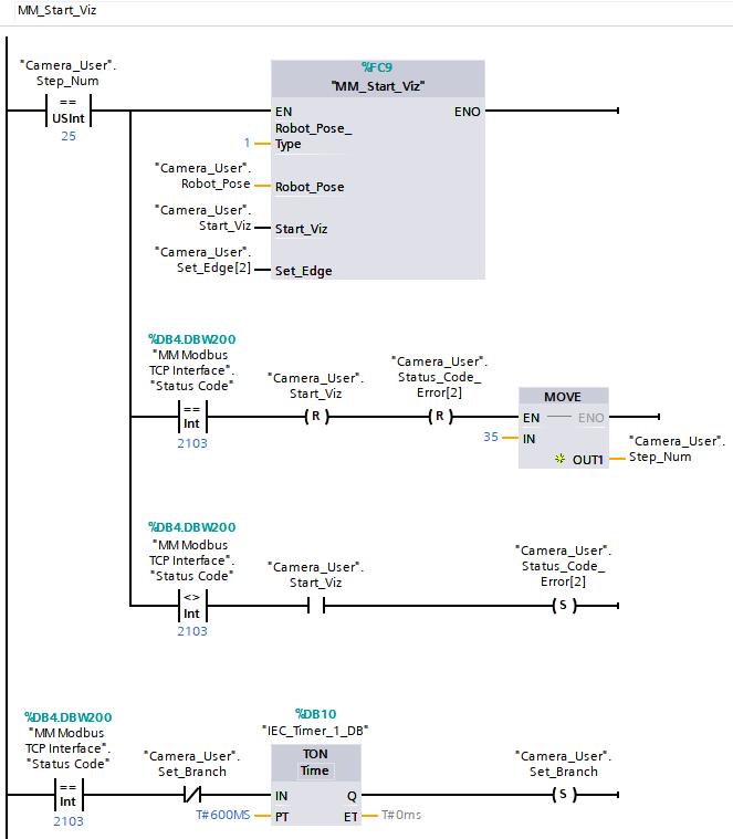
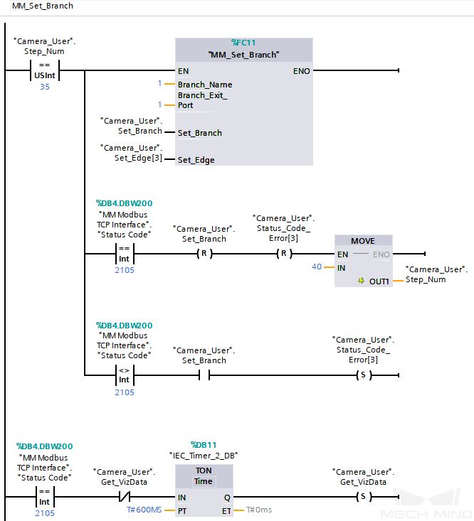
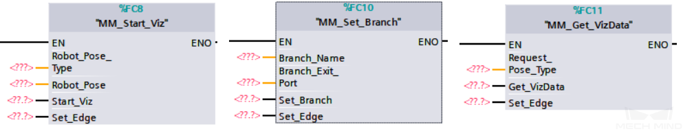
Drag the MM_Start_Viz, MM_Set_Branch, and MM_Get_VizData FCs to Network 5, Network 6, and Network 7, respectively, in the Main OB.
-
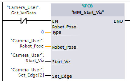
Set the type of pose to be sent by the robot. Change the value of the Robot_Pose_Type port. If the value is set to 0, no image-capturing pose will be sent (for the Eye-to-Hand installation). Click the Camera_User DB. From the Details view panel, drag the parameters to the corresponding input ports of “MM_Start_Viz”.
-
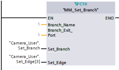
Set the branch parameters in Mech-Viz project. Set the value of Branch_Name and Branch_Exit_Port to 1, and Mech-Viz will take exit port 1 for the “Branch by Msg” Step whose Step ID is 1. Click the Camera_User DB. From the Details view panel, drag the Set_Branch and Set_Edge parameters to the corresponding input ports of the “MM_Set_Branch” FC.
-
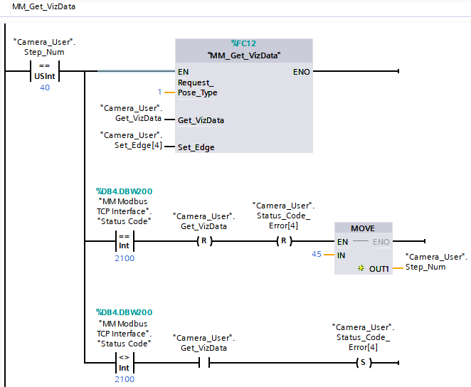
Set the pose type of the obtained waypoints. Change the value of “Request_Pose_Type” to 1, and Mech-Viz will return data in the format of joint positions (instead of TCP). Click the Camera_User DB. From the Details view panel, drag the Get_VizData and Set_Edge parameters to the corresponding input ports of the “MM_Get_VizData” FC.
The Request_Pose_Type parameter here and the Robot_Pose_Type parameters in the MM_Start_Vis and MM_Start_Viz FCs all correspond to the same Pose Type parameter in the MM Modbus TCP Interface DB. Therefore, if these parameters are set to different values, the programming should ensure that the two values do not take effect at the same time. 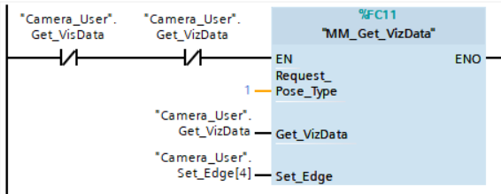
-
In the Program tree panel, right-click PLC_1, and select Download to device ‣ Software (only changes). In the pop-up Load preview window, click “Load” to download the changes to the PLC.
-
In the pop-up Load preview window, click Load to download the changes to the PLC.
Run Mech-Viz Project and Obtain Planned Path
-
In the Main OB window, click the Monitoring on/off icon.
-
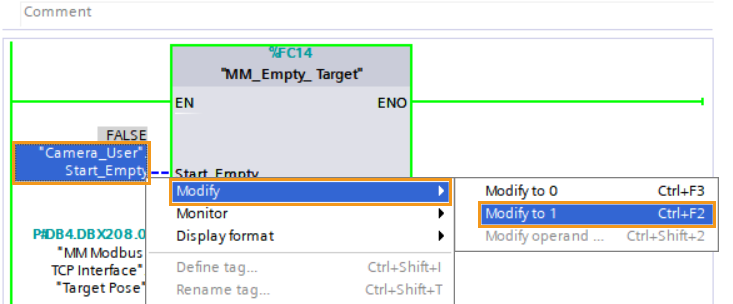
Right-click the “Camera_User”.Start_Empty parameter in “MM_Empty_Target”, and select . Then, reset the value of this parameter.
-
In the MM Modbus TCP Interface DB, the monitor values of Target Pose, Target Label and Speed Percentage are reset.
-
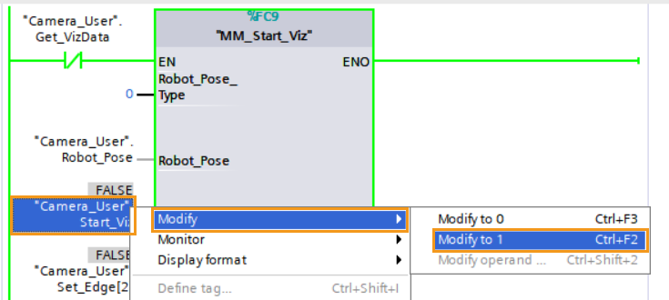
Right-click the “Camera_User”.Start_Viz parameter in “MM_Start_Viz”, select , and start the Mech-Viz project. Then, reset the value of this parameter.
-
Check returned status code: Double-click the MM Modbus TCP Interface DB to open it, and check the monitor value of Status Code. 2103 represents that the project was started successfully. Otherwise, the corresponding error code will be returned. Please refer to Status Codes and Troubleshooting for troubleshooting.

Set Mech-Viz Branch Exit Port
-
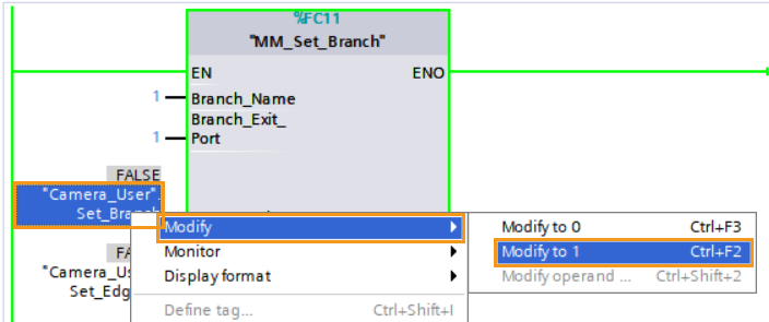
Right-click the “Camera_User”.Set_Branch parameter in “MM_Set_Branch”, select , and select the exit port for the Mech-Viz project. Then, reset the value of this parameter.
-
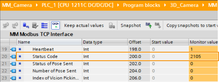
Check returned status code: Double-click the MM Modbus TCP Interface DB to open it, and check the monitor value of Status Code. 2105 represents that the branch was set successfully. Otherwise, the corresponding error code will be returned. Please refer to Status Codes and Troubleshooting for troubleshooting.
Obtain Planned Path from Mech-Viz
-
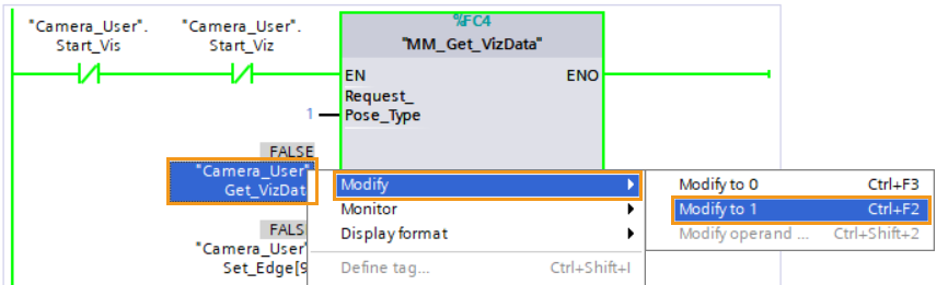
Right-click the “Camera_User”.Get_VizData parameter in “MM_Get_VizData”, select , and obtain the planned path from Mech-Viz. Then, reset the value of this parameter.
-
Check returned status code: Double-click the MM Modbus TCP Interface DB to open it, and check the monitor value of Status Code. 2100 represents that the planned path was successfully obtained. Otherwise, the corresponding error code will be returned. Please refer to Status Codes and Troubleshooting for troubleshooting.
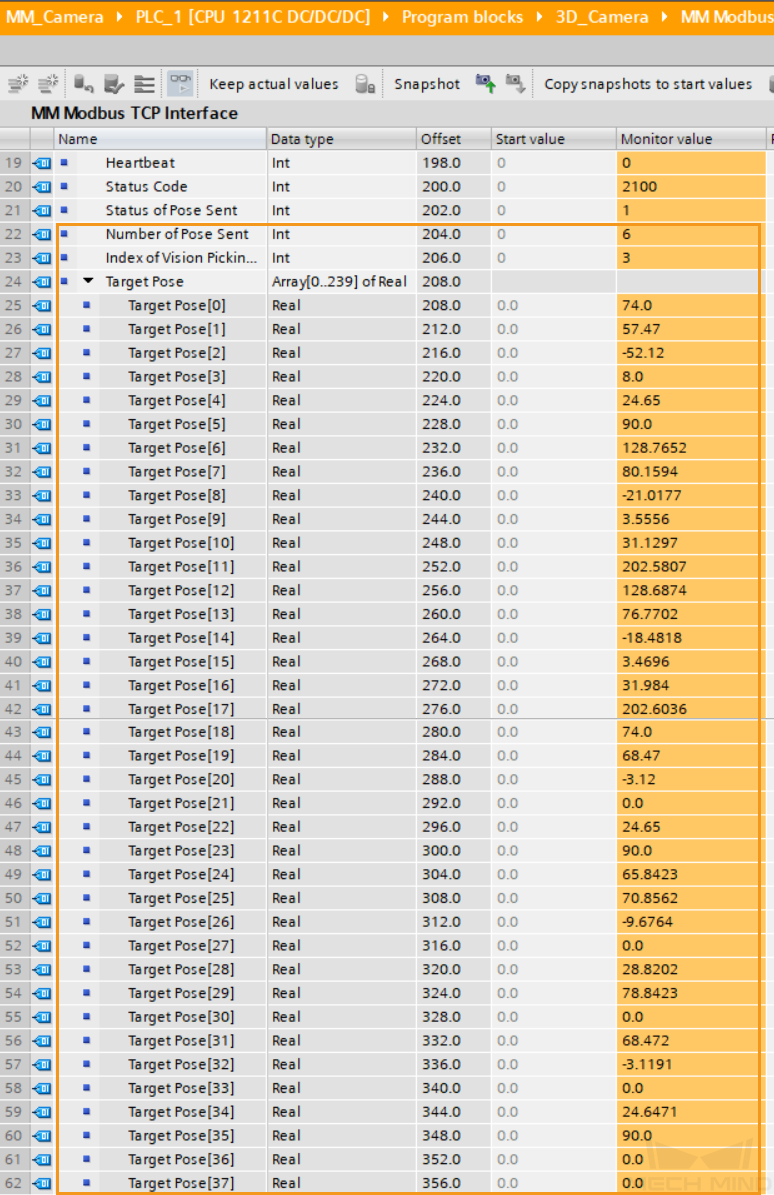
In the picture above, the value of “Number of Pose Sent” is 6, indicating that 6 groups of joint positions are obtained. The data is stored in “Target Pose”. The value of “Index of Vision Move” is 3, indicating that the vision point is the third waypoint in the entire planned robot path.