TCP/IP Interface Commands
This topic introduces the commands of the TCP/IP Standard Interface.
Command 101: Start Mech-Vision Project
This command starts the Mech-Vision project that executes image capturing and performs vision recognition. This command is for applications that use only Mech-Vision but not Mech-Viz.
Parameters in Sent Command
101, Mech-Vision project ID, expected number of vision points, robot pose type, robot pose
Mech-Vision project ID
The number before the project name in the Project List panel in Mech-Vision. Please ensure that the project has been set to auto-loaded, or else the project ID will not be displayed.
Expected number of vision points
The expected number of vision points for Mech-Vision to send. The vision point contains the vision pose, corresponding point cloud, label, scaling, etc.
-
0: Receive all vision points in the recognition result from Mech-Vision. -
Integer greater than 0: Receive the specified number of vision points in the recognition result from Mech-Vision.-
If the total number of vision points is less than the parameter value, all vision points in the recognition result will be received.
-
If the total number of vision points is greater than or equal to the parameter value, the specified number of vision points will be received.
-
| The command used to obtain the vision points is command 102. Command 102 can only fetch at most 20 vision points at a time. One of the returned parameter of command 102 indicates if all the requested vision points have been obtained. If not, please repeat the calling of command 102. |
Robot pose type and robot pose
-
Robot pose type specifies the type of pose of the real robot to be input to Mech-Vision. The value range is 0–3.
-
The values of robot pose depend on the value of robot pose type.
The following table explains the relationship between the two parameters.
| Value of robot pose type | Value of robot pose | Description | Applicable Scenario |
|---|---|---|---|
0 |
0, 0, 0, 0, 0, 0 |
No need to input robot pose to Mech-Vision. |
Project is in the eye-to-hand mode. If the “Path Planning” Step is used in the Mech-Vision project, the planned path starts at the Home point set in the path planning tool. |
1 |
Current joint positions and flange pose of the robot |
Robot joint positions and flange pose must be input to Mech-Vision. |
Project is in the eye-in-hand mode. Applicable to most robots (excluding truss robots). |
2 |
Current flange pose of the robot |
Robot flange pose must be input to Mech-Vision. |
Project is in the eye-in-hand mode. The robot has no joint positions and only flange pose (such as truss robots). |
3 |
Joint positions of the start point of the planned path |
The joint positions of the path start point must be input to Mech-Vision. |
Project is in the eye-to-hand mode and the Mech-Vision project contains the “Path Planning” Step, whose start point needs to be set from the robot side. |
| A pose is composed of position and orientation. The unit of the position is mm, and the orientation is represented by Euler angles, whose unit is degree (°). The unit of joint positions is degree (°). |
Parameters in Returned Data
101, status code
Status code
If there is no error, status code 1102 will be returned. Otherwise, the corresponding error code will be returned.
Examples
The situation of the following example: Application is in the eye-in-hand mode. The command is executed without error, and the current joint positions and flange pose of the robot are received.
TCP send string = 101, 1, 0, 1, 5.18, 14.52, 4.03, 0.09, 72.44, 5.15, 549.56, 50.0, 647.01, 180.0, -1.0, 180.0
TCP received string = 101, 1102
The situation of the following example: Application is in the eye-to-hand mode. The command is executed without error, and the joint positions of the start point of the planned path is received.
TCP send string = 101, 1, 0, 3, 5.18, 14.52, 4.03, 0.09, 72.44, 5.15
TCP received string = 101, 1102
The situation of the following example: The command is executed, but an error code is returned. The error code indicates that the project ID 2 does not exist.
TCP send string = 101, 2, 10, 0
TCP received string = 101, 1011
Command 102: Get Vision Target(s)
This command is called after command 101 to obtain the vision points output by Mech-Vision and automatically transform the vision points into vision targets.
The transformation process, in which the pose of the vision point is transformed into the robot TCP, is as follows:
-
Rotate the poses around their X axes by 180 degrees.
-
Determine whether the definition of the reference frame used by the robot model involves robot base height, and add a vertical offset accordingly.
| This command can only fetch at most 20 vision targets at a time. Therefore, to obtain more than 20 vision targets, please repeat the calling of this command. |
Parameters in Sent Command
102, Mech-Vision project ID
Mech-Vision project ID
The number before the project name in the Project List panel in Mech-Vision. Please ensure that the project has been set to auto-loaded, or else the project ID will not be displayed.
Parameters in Returned Data
102, status code, transmission completion status, number of vision targets, reserved field, vision target, vision target, …, vision target
|
The vision targets are located at the tail of the returned data (at most 20 can be obtained a time). A vision target consists of the robot TCP, label, and velocity. The value of the velocity is always 0. |
Status code
If there is no error, status code 1100 will be returned. Otherwise, the corresponding error code will be returned.
After calling this command, if the vision result from Mech-Vision is not returned within 10 seconds, the error code for timeout will be returned.
Transmission completion status
This parameter indicates whether all vision targets requested have been obtained. The value is 0 or 1.
-
0: Not all the vision targets requested have been obtained. Please repeat the calling of this command until the value of this parameter becomes 1. -
1: All the vision targets requested have been obtained.
If the expected number of vision points specified by command 101 is greater than 20, you can check if all vision points have been obtained by the value of this parameter. If there are still vision points not yet obtained, repeat the calling of this command.
| If command 101 is called before all the vision points requested have been obtained, the unobtained vision points will be cleared. |
Number of vision targets
The number of received vision targets.
-
If the requested number of vision targets is greater than or equal to the number of vision points output by Mech-Vision, all vision points output by Mech-Vision will be obtained.
-
If the requested number of vision targets is smaller than the number of vision points output by Mech-Vision, the requested number of vision points will be obtained.
Value range: 0–20
Reserved field
This field is not currently in use. The value is always 0.
Obtain vision targets
A vision target is composed of 8 data items: the first 6 items are the pose in the form of TCP, the 7th is the label, and the 8th is the velocity.
-
TCP: A TCP consists of the Cartesian coordinates (XYZ, in mm) and Euler angles (ABC, in degrees).
-
Label: The integer label corresponding to the obtained pose. If the labels in the Mech-Vision project are strings, please use the “Label Mapping” Step before the “Procedure Out” Step to map the labels to integers. If there are no labels in the project, the value of this parameter is 0.
-
Velocity: The value of this parameter is always 0. Because the velocity of the robot waypoint is not output by Mech-Vision as part of the vision result.
Examples
The situation of the following example: The command is executed without error.
TCP send string = 102, 1
TCP received string = 102, 1100, 1, 1, 0, 95.7806085592122, 644.5677779910724, 401.1013614123109, 91.12068316085427, -171.13014981284968, 180.0, 0, 0
The situation of the following example: The command is executed, but an error code is returned. The error code indicates that no vision result was output.
TCP send string = 102, 1
TCP received string = 102, 1002
Example for requesting vision targets
The following example sequentially calls the commands 101, 102, and 102 to obtain 22 vision targets. The detailed process is as follows:
-
Command 101 is called, and the content is
101, 1, 0, 1, …, which requests all available vision targets. -
Command 102 is called to obtain the vision targets.
-
The returned data is received, and the content is
102, 1100, 0, 20, …, indicating that not all the available vision targets have been obtained. The returned data includes 20 vision targets. -
Command 102 is called again to obtain the remaining vision targets.
-
The returned data is received, and the content is
102, 1100, 1, 2, …. The returned data includes 2 vision targets, and all vision targets have been received.
Example of command 101.
TCP send string = 101, 1, 0, 1, -0, -20.63239, -107.81205, -0, -92.81818, 0.0016
TCP received string = 101, 1102
Example of command 102 called the first time, obtaining 20 vision targets.
TCP send string = 102, 1

TCP received string = 102, 1100, 0, 20, 0, 95.7806085592122, 644.5677779910724, 401.1013614123108, 31.12068316085427, ...
TCP received string = 78549940546, -179.99999999999991.0.0, 329.228345202334.712.7061697180302.400.9702665047771, ...
TCP received string =39546, -83.62567351596952, -170.87955974536686, -179.99999999999937, 0, 0, 223.37118373658322, ...
TCP received string = 005627, 710.1004355953408, 400.82227273918835, -43.89328326393665, -171.30845207792612, ...
TCP received string = 20.86318821742358, 838.7634193547805, 400.79807564314797, -102.03947940869523, -171.149261231 ...
TCP received string = 390299920645, -179.99999999999994, 0, 0, 303.0722145720921, 785.3254917220695, 400.75827437080, ...
TCP received string = 99668287.77.78291612041707, -171.53941633937786, 179.99999999899997, 0.0, 171.47819668864432, ...
TCP received string = 332193785, 400.6472716208158, -94.3418019038759, -171.10001228964776, -179.39999999999994, ...
TCP received string = 92388542936, 807.5641001485708, 400.6021999602664, - 167.9834797197932.-171.39671274951826, ...
TCP received string = 278.3198007132188, 780.5325992145735, 400.4924381003066, -174.72728396633053, -171.422604771 ...
TCP received string = 3.99999999999994, 0, 0, 183.82195326381233, 862.5171519967056.400.422966515846.-154. 17801945 ...
TCP received string = 173.34301974982765, -180.0, 0, 0
Example of command 102 called the second time, obtaining the remaining 2 vision targets.
TCP send string = 102, 1

TCP received string = 102, 1100, 1, 2, 0, 315.2017788478321, 592.1261793743445, 399.60526335590957, 126.19602189220371, ...
TCP received string = 686127, -171.44430002882129, -1.3381805753922965e-15, 0, 0
Command 103: Switch Mech-Vision Recipe
This command specifies the parameter recipe to be used in the Mech-Vision project.
In Mech-Vision, you can change the values of Step parameters by switching the parameter recipe in use.
The parameters that can be altered by switching parameter recipes usually include point cloud matching model, image matching template, ROI, and confidence threshold.
| This command must be called before command 101 is called. |
Parameters in Sent Command
103, Mech-Vision project ID, recipe ID
Mech-Vision project ID
The number before the project name in the Project List panel in Mech-Vision. Please ensure that the project has been set to auto-loaded, or else the project ID will not be displayed.
Recipe ID
The ID of the parameter recipe in the Mech-Vision project. The ID is a positive integer in the range of 1–99. To view the parameter recipe ID, in the lower right of Mech-Vision, click .
Command 105: Get Result of Step “Path Planning” in Mech-Vision
After calling command 101, call this command to obtain the collision-free picking path planned by the “Path Planning” Step in the Mech-Vision project.
When using this command, set the Port Type parameter of the “Procedure Out” Step in the Mech-Vision project to “Predefined (robot path)”.
| Before calling command 105, please set expected number of vision points of command 101 to 0 to reduce the times of calling command 105. If expected number of vision points of command 101 is set to 1, then every time command 105 is called, only 1 waypoint is returned, and command 105 must be called multiple times to obtain all the waypoints. |
Parameters in Sent Command
105, Mech-Vision project ID, waypoint pose type
Mech-Vision project ID
The number before the project name in the Project List panel in Mech-Vision. Please ensure that the project has been set to auto-loaded, or else the project ID will not be displayed.
Waypoint pose type
This parameter specifies the type of waypoint pose returned by the “Path Planning” Step.
-
1: The waypoint poses are returned in the form of joint positions. -
2: The waypoint poses are returned in the form of TCP.
Parameters in Returned Data
105, status code, transmission completion status, number of waypoints, position of “Vision Move”, waypoint, waypoint, …, waypoint
Status code
If there is no error, status code 1103 will be returned. Otherwise, the corresponding error code will be returned.
Transmission completion status
-
0: Not all the waypoints in the planned path have been obtained. Please repeat the calling of this command until the value of this parameter becomes 1. -
1: All waypoints in the planned path have been obtained.
Number of waypoints
The number of waypoints obtained. The value range is 0–20. If the planned path contains more than 20 waypoints, please repeat the calling this command.
Position of “Vision Move”
The position of the “Vision Move” waypoint in the entire planned path in the path planning Tool.
For example, if the planned path consists of waypoints “Fixed-Point Move_1”, “Fixed-Point Move_2”, “Vision Move”, and “Fixed-Point Move_3” sequentially, the position of “Vision Move” is 3.
If the path does not contain “Vision Move”, the value of this parameter is 0.
Waypoint
A waypoint is composed of 8 data items: the first 6 items are the pose, the 7th is the label, and the 8th is the velocity.
-
Pose: Cartesian coordinates (in mm) and Euler angles (in degree)s, or joint positions (in degrees). The type is determined by the waypoint pose type parameter in the sent command.
-
Label: The integer label corresponding to the obtained pose. If the labels in the Mech-Vision project are strings, please use the “Label Mapping” Step before the “Procedure Out” Step to map the labels to integers. If there are no labels in the project, the value of this parameter is 0.
-
Velocity: the velocity set in the path planning tool.
Examples
The situation of the following example: The command is executed without error.
TCP send string = 105, 1, 2
TCP received string =105,1103,1,5,3,1030.0,0,1260.0,0.0,90.0,-0.0,0,7,1149.114,-298.9656,274.9219,-0.0977,-1.3863,-175.9702,0,7,1149.8416,-296.8585,245.0048,-0.0977,-1.3863,-175.9702,2,7,1149.114,-298.9656,274.9219,-0.0977,-1.3863,-175.9702,0,7,1030.0,0,1260.0,0.0,90.0,-0.0,0,7
The situation of the following example: The command is executed, but an error code is returned. The error code indicates that all poses have already been obtained.
TCP send string = 105, 1,2
TCP received string = 105, 1020
Command 110: Get Custom Output Data from Mech-Vision
This command is used for obtaining the vision result that includes custom port outputs from the corresponding Mech-Vision project. “Custom port outputs” refers to data output by ports other than poses and labels of the “Procedure Out” Step. The output ports can be customized if the “Port Type” parameter of the Step is set to “Custom”.
Calling this command once only fetches one pose and its corresponding labels, scores, etc. (if any) from the vision result. If expecting to receive multiple poses, please call this command multiple times.
Parameters in Sent Command
110, Mech-Vision project ID
Mech-Vision project ID
The number before the project name in the Project List panel in Mech-Vision. Please ensure that the project has been set to auto-loaded, or else the project ID will not be displayed.
Parameters in Returned Data
110, status code, transmission completion status, number of custom data items, robot TCP transformed from object pose, label, custom data items, …, custom data items
Status code
If there is no error, status code 1100 will be returned. Otherwise, the corresponding error code will be returned.
After calling this command, if the vision result from Mech-Vision is not returned within 10 seconds, the error code for timeout will be returned.
Transmission completion status
-
0: Not all poses in the vision result have been obtained. -
1: All poses in the vision result have been obtained.
Number of custom ports
The total number of custom data items other than poses and labels.
Robot TCP transformed from object pose
The TCP in the robot reference frame, composed of Cartesian coordinates (in mm) and Euler angles (in degrees). Mech-Vision outputs object pose, and then the pose is transformed to robot TCP. The “Procedure Out” Step must have a pose port.
The TCP corresponding to the object pose is usually generated by flipping the Z-axis of the object pose.
Label
The object information label corresponding to the pose. The label should be a positive integer. If not, use the “Label Mapping” Step in the Mech-Vision project to map it to a positive integer. If the “Procedure Out” Step does not have a label port, this parameter is filled with 0.
Custom data items
The outputs excluding poses and labels when the “Port Type” parameter of the “Procedure Out” Step in the Mech-Vision project is set to “Custom”.
The custom data items are arranged in alphabetical order of the custom port names.
Command 201: Start Mech-Viz Project
This command is for applications that use both Mech-Vision and Mech-Viz. This command runs the Mech-Viz project (which triggers the corresponding Mech-Vision project to run), and Mech-Viz will plan a robot motion path based on the vision result received from Mech-Vision.
| In Mech-Viz, right-click the project name in the Resources panel and select Autoload Project. |
Mech-Mind Software Suite provides example Mech-Viz projects as a reference for the correct structure of the Mech-Viz project when using the Standard Interface communication. For more information, please refer to Example Mech-Viz Projects for Standard Interface.
Parameters in Sent Command
201, robot pose type, robot pose
Robot pose type and robot pose
-
Robot pose type specifies the type of pose of the real robot to be input to Mech-Viz. The value range is 0–2.
-
The values of robot pose depend on the value of robot pose type.
The following table explains the relationship between the two parameters.
| Value of robot pose type | Value of robot pose | Description | Applicable Scenario |
|---|---|---|---|
0 |
0, 0, 0, 0, 0, 0 |
No need to input robot pose to Mech-Viz. The simulated robot in Mech-Viz moves from JPs = [0, 0, 0, 0, 0, 0] to the first waypoint. |
Project is in the eye-to-hand mode. This setting is not recommended. |
1 |
Current joint positions and flange pose of the robot |
Robot joint positions and flange pose must be input to Mech-Viz. The simulated robot in Mech-Viz moves from the input JPs to the first waypoint. |
This setting is recommended for projects in the eye-in-hand mode. |
2 |
Specific joint positions of the robot |
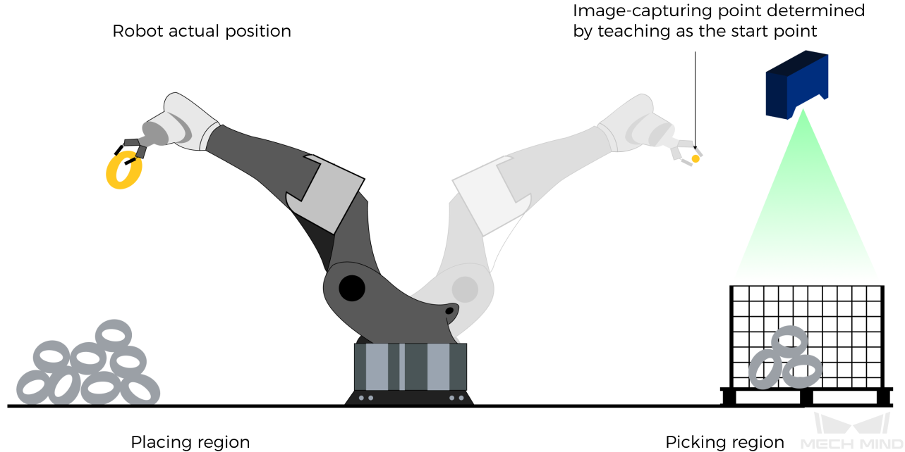
The robot joint positions of a point determined by teaching must be input to Mech-Viz. The input joint positions are used to trigger Mech-Viz to plan the next path in advance while the robot is not in the camera capture region, as shown below. The simulated robot in Mech-Viz moves from the input joint positions to the first waypoint. |
This setting is recommended for projects in the eye-to-hand mode. |
The reason for setting robot pose type to 2 when the project is in the eye-to-hand mode:
In the eye-to-hand mode, the camera can perform image capturing for the next round of path planning before the robot returns to the camera capture region and picking region, shortening the cycle time.
If robot pose type is set to 1, the robot’s current pose is sent to Mech-Viz. The simulated robot will move from the input pose to the first waypoint in the planned path, while the real robot might move to another point first, and then move to the first waypoint.
Therefore, the path of the real robot may contain unpredicted collisions, leading to safety hazards.
In conclusion, robot pose type should be set to 2 for projects in the eye-to-hand mode.
| A pose is composed of position and orientation. The unit of the position is mm, and the orientation is represented by Euler angles, whose unit is degree (°). The unit of joint positions is degree (°). |
Parameters in Returned Data
201, status code
Status code
If there is no error, status code 2103 will be returned. Otherwise, the corresponding error code will be returned.
Examples
The situation of the following example: Application is in the eye-in-hand mode. The command is executed without error, and the current joint positions and flange pose of the robot are received.
TCP send string = 201, 1, 5.18, 14.52, 4.03, 0.09, 72.44, 5.15, 549.56, 50.0, 647.01, 180.0, -1.0, 180.0
TCP received string = 201, 2103
The situation of the following example: Application is in the eye-to-hand mode. The command is executed without error, and the joint positions of the start point of the planned path is received.
TCP send string = 201, 2, 5.18, 14.52, 4.03, 0.09, 72.44, 5.15
TCP received string = 201, 2103
The situation of the following example: The command is executed, but an error code is returned. The error code indicates that the requested pose data are not received.
TCP send string = 201, 1
TCP received string = 201, 2013
Command 202: Stop Mech-Viz Project
This command stops the execution of the Mech-Viz project. This command is only needed if the Mech-Viz project falls into an infinite loop or cannot be stopped normally.
Command 203: Select Mech-Viz Branch
This command is used to select along which branch the Mech-Viz project should proceed. Such branching is achieved by adding the “Branch by Msg” Step(s) to the Mech-Viz project.
Before calling this command, please call command 201 first.
When the next Step is a “Branch by Msg” Step, the Mech-Viz project will wait for this command to specify the exit port to take.
Parameters in Sent Command
203, Step ID of the “Branch by Msg” Step, exit port number
Step ID of the “Branch by Msg” Step
Step ID of the “Branch by Msg” Step. The value should be a positive integer. The Step ID is displayed in the parameters of the Step.
Exit port number
The number of the exit port to take. The Mech-Viz project will proceed along the workflow connected to this exit port. The value range is 1–99.
| This parameter value should be 1 greater than the exit port number displayed in the Step. For example, to select exit port 0, you should set the value of this parameter to 1. |
Parameters in Returned Data
203, status code
Status code
If there is no error, status code 2105 will be returned. Otherwise, the corresponding error code will be returned.
Examples
The situation of the following example: The command is executed without error.
TOP send string = 203, 1, 1
TCP received string = 203, 2105
The situation of the following example: The command is executed, but an error code is returned. The error code indicates that exit port number is invalid.
TCP send string = 203, 1, 3
TCP received string = 203, 2018
Command 204: Set Move Index
This command sets the value of the Current Index parameter of the specified Mech-Viz Step. Steps that have this parameter include “Move by List”, “Move by Grid”, “Custom Pallet Pattern”, and “Predefined Pallet Pattern”.
Before calling this command, please call command 201 first.
Parameters in Sent Command
204, Step ID, Current Index value
Step ID
Step ID of the “Branch by Msg” Step. The value should be a positive integer. The Step ID is displayed in the parameters of the Step.
Current Index value
The Current Index value that should be set the next time this Step is executed.
When this command is sent, the Current Index value in Mech-Viz will become the parameter value minus 1.
When the Mech-Viz project runs to the Step specified by this command, the Current Index value in Mech-Viz will be increased by 1 to become the parameter’s value.
Parameters in Returned Data
204, status code
Status code
If there is no error, status code 2106 will be returned. Otherwise, the corresponding error code will be returned.
Examples
The situation of the following example: The command is executed without error.
TCP send string = 204, 2, 6
TCP received string = 204, 2106
The situation of the following example: The command is executed, but an error code is returned. The error code indicates that the Step corresponding to the Step ID does not exist.
TCP send string = 204, 3, 6
TCP received string = 204, 2028
Command 205: Get Planned Path
This command obtains the planned path from Mech-Viz.It should be used after calling command 201.
This command can only fetch at most 20 waypoints at a time. Therefore, to obtain more than 20 waypoints, please repeat the calling of this command.
|
If any waypoint of move-type Steps should not be sent to the robot, please uncheck the “Send Waypoint” option in the parameters of this Step. |
Parameters in Sent Command
205, waypoint pose type
Waypoint pose type
This parameter specifies the type of waypoint pose returned by Mech-Viz.
-
1: The waypoint poses are returned in the form of joint positions (JPs). -
2: The waypoint poses are returned in the form of tool center point (TCP).
Parameters in Returned Data
205, status code, transmission completion status, number of waypoints, position of “Vision Move”, waypoint, waypoint, …, waypoint
Status code
If there is no error, status code 2100 will be returned. Otherwise, the corresponding error code will be returned.
| After calling this command, if the vision result from Mech-Viz is not returned within 10 seconds, the error code for timeout will be returned. |
Transmission completion status
-
0: Not all the waypoints in the planned path have been obtained. Please repeat the calling of this command until the value of this parameter becomes 1. -
1: All waypoints in the planned path have been obtained.
Number of waypoints
The number of waypoints obtained. The value range is 0–20. This command can only fetch at most 20 waypoints at a time. Therefore, to obtain more than 20 waypoints, please repeat the calling of this command.
Position of “Vision Move”
The position of the “Vision Move” waypoint in the entire planned path.
For example, if the planned path consists of waypoints “Fixed-Point Move_1”, “Fixed-Point Move_2”, “Vision Move”, and “Fixed-Point Move_3” sequentially, the position of “Vision Move” is 3.
If the path does not contain “Vision Move”, the value of this parameter is 0.
Waypoint
A waypoint is composed of 8 data items: the first 6 items are the pose, the 7th is the label, and the 8th is the velocity.
-
Pose: Cartesian coordinates (in mm) and Euler angles (in degree)s, or joint positions (in degrees). The type is determined by the “waypoint pose type” parameter in the sent command.
-
Label: The integer label corresponding to the obtained pose. If the labels in the Mech-Vision project are strings, please use the “Label Mapping” Step before the “Procedure Out” Step to map the labels to integers. If there are no labels in the project, the value of this parameter is 0.
-
Velocity: The non-zero value in front of the percentage sign in the velocity parameter of move-type Steps.
Examples
The situation of the following example: The command is executed without error.
TCP send string = 205, 1

TCP received string =205, 2100, 1, 2, 2, 8.307755332057372, 15.163476541700463, -142.1778810972881, -2.7756047848536745, -31.44046012182799, -96.94907235126934, 0, 64, 8.2 42574265592342, 12.130080796661591, -141.75872288706663-2.513533225987894, -34.8905853 039525, -97.19108378871277, 0, 32
The situation of the following example: The command is executed, but an error code is returned. The error code indicates that the project encountered an issue and was terminated.
TCP send string = 205, 1
TCP received string = 205, 2008
Command 206: Get DO List
This command gets the planned DO signal list. The DO signal list is used to control multiple grippers or multiple suction cup sections.
Before calling this command, please call command 205 to obtain the planned motion path from Mech-Viz.
Please deploy the Mech-Viz project based on the template project and set the corresponding suction cup configuration file. The template project is stored in the Mech-Mind Software Suite installation directory (in the Mech-Center\tool\viz_project\suction_zone folder).
In the parameters of the Mech-Viz “Set DO List” Step:
-
Select “Standard Interface” under “Receiver”.
-
Select “Get DO List from ‘Vision Move’”.
-
Select a Vision Move Step that needs the DO signal list in the drop-down list of the “Select ‘Vision Move’” parameter.
Parameters in Returned Data
206, status code, DO signal value, DO signal value, ..., DO signal value
Status code
If there is no error, status code 2102 will be returned. Otherwise, the corresponding error code will be returned.
DO signal value
64 DO signal values are located at the tail of the returned data. The signal values are integers.
Value range: 0–999
Placeholder value: -1
Examples
The situation of the following example: The command is executed without error. Two DO signal values, 11 and 12, are obtained.
TCP send string: 206
TCP receive string: 206, 2102, 11, 12, -1, -1, -1, -1, -1, -1, -1, -1, -1, -1, -1, -1, -1, -1, -1, -1, -1, -1, -1, -1, -1, -1, -1, -1, -1, -1, -1, -1, -1, -1, -1, -1, -1, -1, -1, -1, -1, -1, -1, -1, -1, -1, -1, -1, -1, -1, -1, -1, -1, -1, -1, -1, -1, -1, -1, -1, -1, -1, -1, -1, -1, -1
The situation of the following example: The command is executed, but an error code is returned. The error code indicates that a valid DO list is not provided.
TCP send string: 206
TCP receive string: 206, 2011, -1, -1, -1, -1, -1, -1, -1, -1, -1, -1, -1, -1, -1, -1, -1, -1, -1, -1, -1, -1, -1, -1, -1, -1, -1, -1, -1, -1, -1, -1, -1, -1, -1, -1, -1, -1, -1, -1, -1, -1, -1, -1, -1, -1, -1, -1, -1, -1, -1, -1, -1, -1, -1, -1, -1, -1, -1, -1, -1, -1, -1, -1, -1, -1
Command 207: Read Mech-Viz Step Parameter
This command sets the values of specified parameters of specified Steps.
Please specify the Step IDs and parameters to be read in menu: Deployment Settings [ Mech-Interface > Advanced Settings > Property Config ] in Mech-Center.
Parameters in Sent Command
207, config ID
Config File Content Format
read, config ID, Step ID, parameter key name
The lines starting with “#” are comment lines and do not take part in the execution of this command.
read
The string “read” indicates that the corresponding parameter value should be read from Mech-Viz.
config ID
A positive integer used for specifying the ID of the read operation. Each config ID can only be used for reading one parameter. To read multiple parameters, use different config IDs.
Step ID
The Step ID of the Step whose parameter is to be read.
The Step ID is displayed in the parameters of the Step.
Parameter key name
The key name of the parameter to be read. You can check the key name in in the menu bar of Mech-Viz. Note that the developer mode must be enabled first.
Parameters in Returned Data
207, status code, Step parameter value
Status code
If there is no error, status code 2109 will be returned. Otherwise, the corresponding error code will be returned.
Step parameter value
The value of the specified parameter of the specified Step in the Mech-Viz project.
Supported data type: INT, FLOAT, STRING.
Examples
The situation of the following example: The command is executed without error. The parameter value is successfully read.
TCP send string = 207, 1
TCP received string = 207, 2109, 10
The situation of the following example: The command is executed, but an error code is returned. The error code indicates that the specified parameter is not found.
TCP send string = 207, 1
TCP received string = 207, 2041
Command 208: Set Mech-Viz Step Parameter
This command sets the values of specified parameters of specified Steps.
Please specify the Step IDs, parameters and parameter values to be set in menu: Deployment Settings [ Mech-Interface > Advanced Settings > Property Config ] in Mech-Center.
Parameters in Sent Command
208, config ID
Config File Content Format
write, config ID, Step ID, parameter key name
write
The string “write” indicates that the corresponding parameter value should be set into Mech-Viz.
config ID
A positive integer used for specifying the ID of the read operation. Each config ID can be used for setting multiple parameters.
Step ID
The Step ID of the Step whose parameter is to be set.
The Step ID is displayed in the parameters of the Step.
Parameter key name
The key name of the parameter to be set. You can check the key name in in the menu bar of Mech-Viz. Note that the developer mode must be enabled first.
Value
The value to be set to the specified parameter.
Numbers ands strings are supported.
Examples
The situation of the following example: The command is executed without error. The parameter value is successfully set.
TCP send string = 208, 1
TCP received string = 208, 2108
The situation of the following example: The command is executed, but an error code is returned. The error code indicates that the config ID is not found.
TCP send string = 208, 10
TCP received string = 208, 3008
Command 210: Get Waypoint with Depalletizing Planning Data
This command obtains a single planned waypoint from Mech-Viz. The waypoint may be of a Vision Move Step, or of another move-type Step. A waypoint may contain pose, velocity, tool information, workobject information, etc.
Waypoints in a planned path can be divided into two types: those of the “Vision Move” Step and those of other move-type Steps.
-
All waypoints contain the following data: motion type (joint motion or linear motion), tool number and velocity.
-
The waypoints of the “Vision Move” Step also contain depalletizing planning data.
-
If custom ports are defined for the “Procedure Out” Step in Mech-Vision, then the waypoints of the “Vision Move” Step also contain custom port outputs.
|
Parameters in Sent Command
210, expected data format
Expected data format
Below are the explanations of the four possible data formats that can be returned by this command.
| Value of the expected data format parameter | Format of returned data (explained below) |
|---|---|
1 |
Pose (joint positions), motion type, tool number, velocity, number of custom ports, custom port output, custom port output, … custom port output |
2 |
Pose (TCP), motion type, tool number, velocity, number of custom ports, custom port output, custom port output, … custom port output |
3 |
Pose (joint positions), motion type, tool number, velocity, depalletizing planning data, number of custom ports, custom port output, custom port output, … custom port output |
4 |
Pose (TCP), motion type, tool number, velocity, depalletizing planning data, number of custom ports, custom port output, custom port output, … custom port output |
Parameters in Returned Data
210, status code, transmission completion status, waypoint type, pose, motion type, gripper ID, velocity, depalletizing planning data, number of custom ports, custom port outputs
| Whether the returned data contains depalletizing planning data and/or custom port outputs depends on the value of the expected data format parameter in the sent commend. |
Status code
If there is no error, status code 2100 will be returned. Otherwise, the corresponding error code will be returned.
Transmission completion status
-
0: Not all output waypoints have been obtained. -
1: All output waypoints have been obtained.
Waypoint type
-
0: The waypoint is not a “Vision Move” Step waypoint. -
1: The waypoint is a “Vision Move” Step waypoint.
Pose
The pose of the waypoint, as joint positions (in degrees) or TCP, which is composed of Cartesian coordinates (XYZ in mm) and Euler angles (ABC in degrees).
Motion type
-
1: joint motion, MOVEJ -
2: linear motion, MOVEL
Tool number
The index number of the tool to be used at this waypoint. -1 means no tool is used.
Velocity
Velocity of the waypoint, equal to the velocity setting in the corresponding move-type Step in the Mech-Viz project multiplied by the global velocity setting in Mech-Viz, in the format of percentage.
Depalletizing planning data
Data used in planning multi-pick depalletizing tasks. This data is part of the waypoint of the “Vision Move” Step. The following data are included:
-
Label: composed of 10 integers. If fewer than 10 labels are obtained, the rest of the digits are filled with 0.
-
Number of picked workobjects
-
Number of workobjects to be picked this time
-
Edge-corner ID of vacuum gripper: used to specify the gripper corner to which the workobject is aligned. Can be checked by double-clicking the corresponding tool in the Resources panel in Mech-Viz and then selecting “Configure control logic”.
-
TCP offset: The offset between the tool pose at the center of the to-pick workobjects and the actual tool pose.
-
Workobject orientation: whether the X-axis of the workobject reference frame is aligned with the X-axis of the tool reference frame (value: 0 or 1).
-
Dimensions of the workobjects combined.
Number of custom ports
The number of outputs excluding poses and labels when the “Port Type” parameter of the “Procedure Out” Step in the Mech-Vision project is set to “Custom”. These data are part of the waypoint of the “Vision Move” Step.
Custom data items
The outputs excluding poses and labels when the “Port Type” parameter of the “Procedure Out” Step in the Mech-Vision project is set to “Custom”.
The custom port outputs are arranged in alphabetical order of the custom port names.
Command 501: Input Object Dimensions to Mech-Vision
This command is used for dynamically inputting object dimensions into the Mech-Vision project. Please check the actual object dimensions before running the Mech-Vision project.
The Mech-Vision project should contain the “Read Object Dimensions” Step, and the Read Sizes from Properties parameter of this Step should be checked.
Parameters in Sent Command
501, Mech-Vision project ID, length, width, height
Mech-Vision project ID
The number before the project name in the Project List panel in Mech-Vision. Please ensure that the project has been set to auto-loaded, or else the project ID will not be displayed.
Length, width, height
The object dimensions (length, width, height) to be input to the Mech-Vision project. The dimensions will be read into the “Read Object Dimensions” Step.
Unit: mm
Parameters in Returned Data
501, status code
Status code
If there is no error, status code 1108 will be returned. Otherwise, the corresponding error code will be returned.
Examples
The situation of the following example: The command is executed without error.
TCP send string: 501, 1, 100, 200, 300
TCP receive string: 501, 1108
The situation of the following example: The command is executed, but an error code is returned. The error code indicates that the length of the sent command is incorrect (missing the “height” value).
TCP send string: 501, 1, 100, 200
TCP receive string: 501, 3002
Command 502: Input TCP to Mech-Viz
This command is used for dynamically inputting robot TCP into the Mech-Viz project. The input TCP is read by the “External Move” Step.
Please deploy the Mech-Viz project based on the template project. The template project is stored in the Mech-Mind Software Suite installation directory (in the Mech-Center\tool\viz_project\outer_move folder).
Place the “External Move” Step in an appropriate position in the workflow.
This command must be called before command 201 is called.
Parameters in Sent Command
502, robot TCP
Robot TCP
The robot TCP used to set the waypoint of the “External Move” Step.
Command 601: Notify
This command does not need to be initiated by the user.
It will be executed when the Mech-Viz / Mech-Vision project runs to a “Notify” Step to send the notification message defined in the Step.
In Mech-Vision, the “Notify” Step must be named “Standard Interface Notify”.
In Mech-Viz, please check the “StandardInterface” option in the “Receiver” parameter of the “Notify” Step.
Command 701: Calibration
This command is used for hand-eye calibration (camera extrinsic parameter calibration).
This command synchronizes the calibration status with Mech-Vision and obtains the next calibration point that the robot needs to reach from Mech-Vision.
This command must be called multiple times to complete the calibration.
Parameters in Sent Command
701, calibration status, flange pose, joint positions
Calibration status
Value range: 0–2
-
0: Notifies Mech-Vision to initiate the calibration. -
1: The previous calibration point was successfully received by the robot. -
2: The previous calibration point was not successfully received.
Flange pose
The current flange pose of the robot. A pose is composed of position and orientation. The unit of the position is mm, and the orientation is represented by Euler angles, whose unit is degree (°).
Joint positions
Current joint positions of the robot. The unit is degree.
| You only need to specify either the flange pose or the joint positions.Fill the other parameter with six 0s. |
Parameters in Returned Data
701, status code, calibration status, flange pose of the next calibration point, joint positions of the next calibration point
Status code
If there is no error, status code 7101 will be returned. Otherwise, the corresponding error code will be returned.
Calibration status
-
0: The calibration is in progress. -
1: The calibration is completed.
Flange pose of the next calibration point
The flange pose of the next calibration point to which the robot should move. The robot program can choose to use either the flange pose or the joint positions.
Joint positions of the next calibration point
The joint position of the next calibration point to which the robot should move.
| Choose either the flange pose or the joint positions to use. |
Examples
The situation of the following example: The calibration is initiated and the first calibration point is obtained.
TCP send string = 701, 0, 1371.62147, 25.6, 1334.3529, 148.58471, -179.24347, 88.75702, 88.86102, -7.11107, -28.82309, -0.44014, -67.6509, 31.4764
TCP received string = 701, 7101, 0, 1271.6969, -74.3374, 1334.34094, -3128.422, 179.2412, -91.11236, 93.28109, -12.0273, -32.8811, -0.37183, -68.41364, 27.02411
The situation of the following example: The command is executed to obtain the next calibration point from Mech-Vision.
TCP send string = 701, 1, 1271.6969, -74.3374, 1334.34094, -3128422, 1792412, -91.11236, 93.28109, -12.0273, -32.8811, -0.37183, -68.41364, 27.02411
TCP received string = 701, 7101, 0, 1471.62226, -74.40452, 1334.34235, 148.56924, -179.24432, 88.74148, 92.8367, -2.14999, -24.25433, -0.39222, -67.23261, 27.485225| This process must be repeated to obtain all the calibration points. |
The situation of the following example: The last calibration point is obtained, and the calibration program can be terminated after the robot moves to this point.
TCP send string = 701, 1, 1371.60876, 25.53615, 1384.45532, -20.82704, 179.22026, -72.77879, 88.88467, -7.42242, -26.68142, -0.2991, -69.95593, 39.26262
TCP received string = 701, 7101, 1, 1371.62147, 25.6, 1334.3529, 148.58471, -179.24347, 88.75702, 88.86102, -7.11107, -28.82309, -0.44014, -67.6509, 31.4764
Command 901: Get Software Status
This command is designed for obtaining the execution status of Mech-Vision, Mech-Viz, and Mech-Center.
Currently, this command is capable of checking whether Mech-Vision is ready to run projects.
Parameters in Returned Data
901, status code
Status code
Software status. Status code 1101 indicates that Mech-Vision is ready to run projects. Other status code indicates that Mech-Vision is not ready. The command is currently capable of checking whether Mech-Vision is ready to run projects.
Examples
The situation of the following example: The command is executed, and the status code indicating that the Mech-Vision project is ready is returned.
TCP send string = 901
TCP received string = 901, 1101
The situation of the following example: The command is executed, but an error code is returned. The error code indicates that the Mech-Vision is not ready.
TCP send string = 901
TCP received string = 901, 1001| Before calling this command, please make sure that the Autoload Solution or Autoload Project option is selected for the current solution/project. |