TCP/IP Interface Commands
This guide introduces the TCP/IP commands for the Standard Interface communication. The basic information about Standard Interface commands is as follows:
-
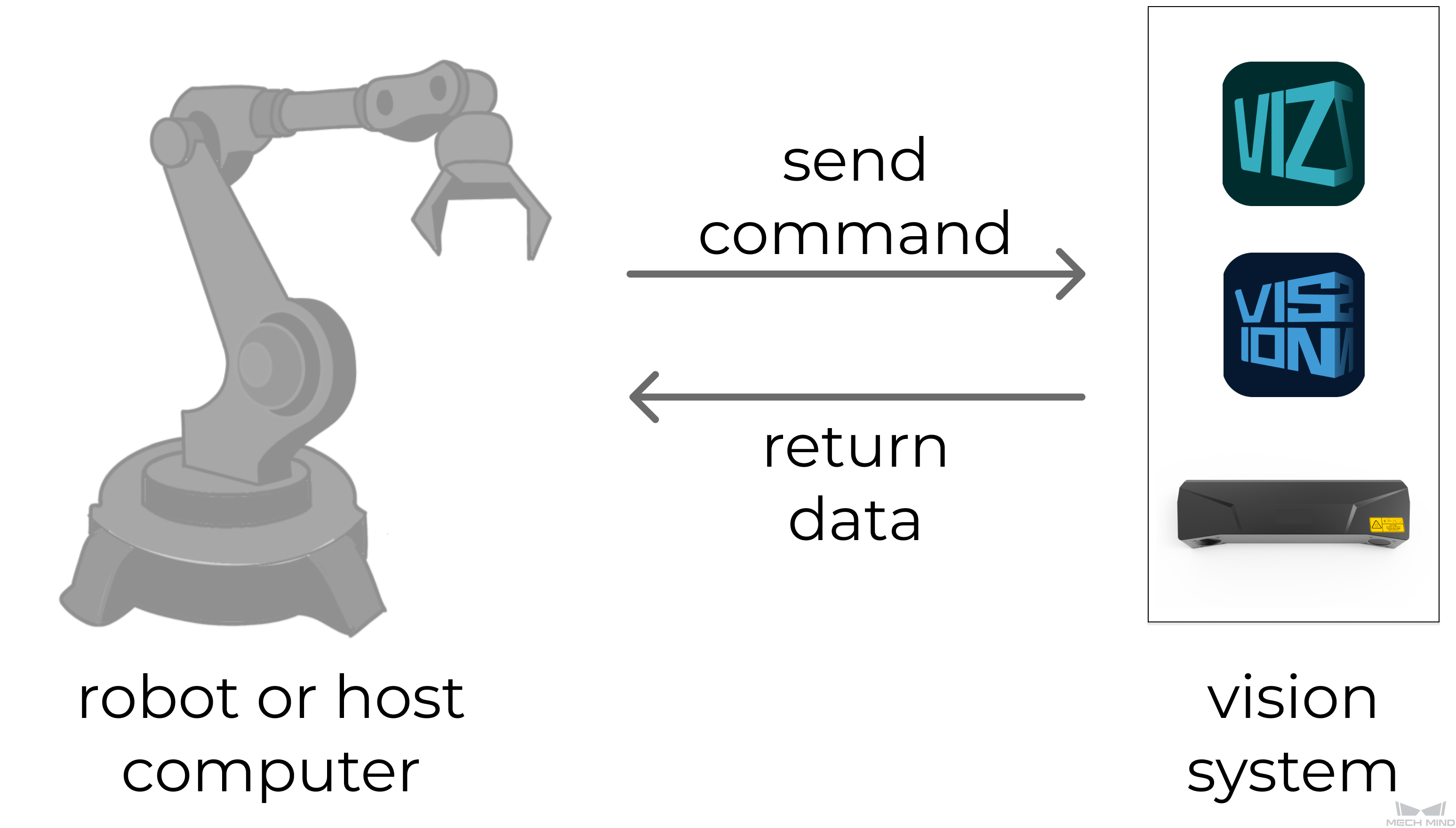
Sending and receiving commands: Robot or the host computer (the client) sends commands to Mech-Mind Vision System (the server), and Mech-Mind Vision System returns the processed data to the robot or the host computer.
-
Data formats of sent and received commands: Both ASCII and HEX are supported.
-
The delimiter in the ASCII strings is the English comma, and the terminator is \r. Examples in this guide are in the ASCII format and the string terminator (\r) is omitted. For example, Command 103 (with the terminator) sent by the robot to the vision system is as follows:
103,1,2\r -
The byte orders of HEX (hexadecimal number) are big-endian and little-endian. The byte length in the sent commands is 64, a fixed length. If, in practice, the data has less than 64 bytes, fill in the remaining fields with 0s. If, in practice, the data has more than 64 bytes, the vision system will ignore the extra fields.
Take the ASCII format string “103,1,2” as an example. When the HEX big-endian format is adopted, the sent command is as below. The decimal number 103 corresponds to the hexadecimal number 67. The hexadecimal number 67 is represented in big-endian byte order as 00 00 00 67.
00 00 00 67 00 00 00 01 00 00 00 02 00 00 00 00 00 00 00 00 00 00 00 00 00 00 00 00 00 00 00 00 00 00 00 00 00 00 00 00 00 00 00 00 00 00 00 00 00 00 00 00 00 00 00 00 00 00 00 00 00 00 00 00When the HEX little-endian format is adopted, the sent command is as below. The hexadecimal number 67 is represented as 67 00 00 00 in the little-endian byte order.
67 00 00 00 01 00 00 00 02 00 00 00 00 00 00 00 00 00 00 00 00 00 00 00 00 00 00 00 00 00 00 00 00 00 00 00 00 00 00 00 00 00 00 00 00 00 00 00 00 00 00 00 00 00 00 00 00 00 00 00 00 00 00 00
-
-
Unit of data:
-
The unit of joint positions is degree (°).
-
Robot’s flange pose or Tool Center Point (TCP) consists of the position and pose. The position is represented in XYZ coordinates and is measured in millimeters (mm); the pose is represented in Euler angles and is measured in degrees (°).
-
-
Vision point and waypoint:
-
Vision point: An object recognized by Mech-Vision. A vision point has information including the object pose, label, velocity, dimensions, custom port output, etc.
-
Waypoint: Each point that the robot reaches when moving along the planned path. A waypoint has information including the robot pose, label, move type, velocity, etc. Waypoints can be divided into two categories:
-
Vision Move waypoints, which refer to the waypoints corresponding to the “Vision Move” Step.
-
Non-Vision Move waypoints, which refer to the waypoints corresponding to Move-type Steps other than the “Vision Move” Step.
-
-
Command Overview
Command 100: Trigger Mech-Vision Project and Get Results
Description
This command triggers the following operations in sequence: First, it switches Mech-Vision parameter recipe (which is skipped if the project does not have a parameter recipe). Second, it triggers the Mech-Vision project. Third, it gets vision results (i.e., vision points, waypoints, or custom port output) from the vision system.
| Robot moves only after the vision system takes an image and returns the vision results. |
Command Format
100, Mech-Vision project ID, parameter recipe ID, returned data format, robot joint positions, robot flange pose
Mech-Vision project ID
You can check the ID of a Mech-Vision project in the “Project List” panel. The number before the name of a project is its ID.
Parameter recipe ID
The ID of the parameter recipe in the Mech-Vision project. The ID is a positive integer, from 1 to 99. For details on checking the ID, refer to Parameter Recipe Configuration.
| Set this parameter to 0 if the Mech-Vision project doesn’t need to switch a parameter recipe. |
Returned data format
Value |
Returned data (explained below) |
1 |
100, status code, status of transmitting vision points, number of vision points, reserved field, vision point 1 (TCP, label, velocity), vision point 2 (TCP, label, velocity), … |
2 |
100, status code, status of transmitting vision points, number of elements in custom output data (N), pose, label, element 1 in custom output data, ..., element N in custom output data |
3 |
100, status code, status of transmitting waypoints, number of waypoints, position of “Vision Move” in planned path, waypoint 1 (joint positions, label, velocity), waypoint 2 (joint positions, label, velocity), ... |
4 |
100, status code, status of transmitting waypoints, number of waypoints, position of “Vision Move” in planned path, waypoint 1 (TCP, label, velocity), waypoint 2 (TCP, label, velocity), ... |
Robot joint positions & robot flange pose
Robot sends its current joint positions and flange pose to the Mech-Vision project.
Returned Data Format
Returned data format 1
100, status code, status of transmitting vision points, number of vision points, reserved field, vision point 1 (TCP, label, velocity), vision point 2 (TCP, label, velocity), …
Status code
Status code 1100 is returned for a successful command execution. For a failed command execution, the specific error code is returned. For details, refer to Status Codes and Troubleshooting.
Status of transmitting vision points
This parameter specifies whether all vision points are obtained. The value is 0 or 1.
-
0: Not all vision points are obtained.
-
1: All vision points are obtained.
|
Number of vision points
This parameter specifies the number of vision points that the robot side expects to obtain.
Reserved field
This field is not currently in use. The value is 0.
Vision point
Each vision point has 8 data elements The first 6 elements are the TCP, the 7th is the label, and the 8th is the velocity.
-
Tool pose: Robot’s tool center point.
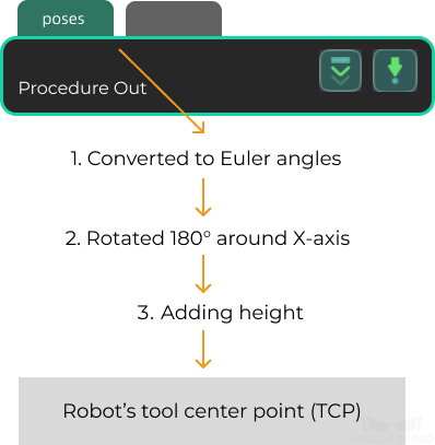
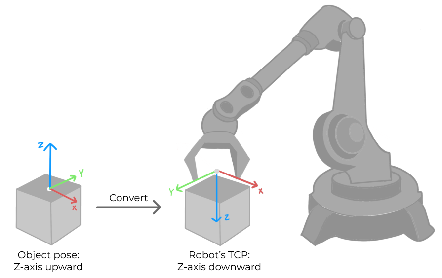
The vision system converts the object pose in the vision point (i.e., output of the “poses” port of the “Procedure Out” Step) to the robot tool pose.
-
Convert the object pose from the form of quaternions to Euler angles.
-
Rotate the object’s pose around the X-axis by 180° to orient its Z-axis downward.
-
-
Label: The label corresponding to a pose (i.e., output of the “labels” port in the “Procedure Out” Step), which is an integer.
-
The label must be an integer-formatted string. If not, add a “Label Mapping” Step BEFORE the “Procedure Out” Step to convert the format of the label to an integer-formatted string.
-
If the “Procedure Out” Step does not have a “labels” port, the value of the “label” parameter is 0.
-
-
Velocity: The value of this parameter is 0 by default.In most cases, vision points output by Mech-Vision do not have information of the object velocity.
Returned data format 2
100, status code, status of transmitting vision points, number of elements in custom output data (N), pose, label, element 1 in custom output data, ..., element N in custom output data
Status code
Status code 1100 is returned for a successful command execution. For a failed command execution, the specific error code is returned. For details, refer to Status Codes and Troubleshooting.
Status of transmitting vision points
This parameter specifies whether all vision points are obtained. The value is 0 or 1.
-
0: Not all vision points are obtained.
-
1: All vision points are obtained.
|
Number of elements in custom output data
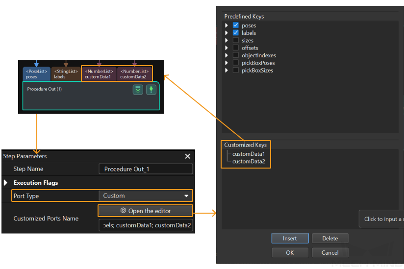
The total number of elements in data output by all custom ports. For example, outputs of the ports of the “Procedure Out” Step are presented in the following table. “customData1” and “customData2” are custom ports, with 3 and 2 columns in their respective output data. Therefore, the number of elements in custom output data is 5, which is the result of adding 3 and 2.
Port name |
poses |
labels |
customData1 |
customData2 |
Output |
[ [0, 0, 0, 1, 0, 0, 0], [0, 0, 0, 1, 0, 0, 0] ] |
[ "0", "1" ] |
[ [0, 0, 1], [1, 0, 0] ] |
[ [0, 0], [1, 1] ] |
Number of rows (i.e. number of items in the list) |
2 |
2 |
2 |
2 |
Number of columns (i.e. number of elements in each item) |
7 |
1 |
3 |
2 |
Pose
This parameter specifies the robot tool pose corresponding to one vision point. The vision system converts the object pose in the vision point (namely, output of the “poses” port of the “Procedure Out” Step) to the robot tool pose. The process is as follows.
-
Convert the object pose from the form of quaternions to Euler angles.
-
Rotate the object’s pose around the X-axis by 180° to orient its Z-axis downward.
Label
The label of one vision point that is output by the “labels” port of the “Procedure Out” Step.
|
Element in custom output data
“Elements in custom output data” are data output by all custom ports concerning one vision point. The total number is specified by the number of elements in custom output data parameter. For example, data output from ports of the “Procedure Out” Step is presented in the following table. The elements in custom output data of the first vision point are [0, 0, 1] and [0, 0]; and the elements in custom output data of the second vision point are [1, 0, 0] and [1, 1].
Port name |
poses |
labels |
customData1 |
customData2 |
Port data |
[ [0, 0, 0, 1, 0, 0, 0], [0, 0, 0, 1, 0, 0, 0] ] |
[ "0", "1" ] |
[ [0, 0, 1], [1, 0, 0] ] |
[ [0, 0], [1, 1] ] |
The first vision point |
[0, 0, 0, 1, 0, 0, 0] |
0 |
[0, 0, 1] |
[0, 0] |
The second vision point |
[0, 0, 0, 1, 0, 0, 0] |
1 |
[1, 0, 0] |
[1, 1] |
| The custom port outputs are arranged in the alphabetical order of the names of custom ports. |
Returned data format 3
100, status code, status of transmitting waypoints, number of waypoints, position of “Vision Move” in planned path, waypoint 1 (joint positions, label, velocity), waypoint 2 (joint positions, label, velocity), ...
Status code
Status code 1103 is returned for a successful command execution. For a failed command execution, the specific error code is returned. For details, refer to Status Codes and Troubleshooting.
Status of transmitting waypoints
This parameter specifies whether all waypoints are obtained. The value is 0 or 1.
-
0: Not all waypoints are obtained.
-
1: All waypoints are obtained.
|
Number of waypoints
This parameter specifies the number of waypoints that the robot side expects to obtain.
Position of “Vision Move” in planned path
This parameter indicates the position of the Vision Move waypoint corresponding to the “Vision Move” Step of the path planning tool in the entire path. If the path does not contain a “Vision Move” waypoint, the value of this parameter is 0.
If the planned path consists of waypoints “Fixed-Point Move_1, Fixed-Point Move_2, Vision Move, Fixed-Point Move_3” in sequence, then the position of the Vision Move waypoint is 3.
Waypoint
Each waypoint has 8 data elements. The first 6 elements are joint positions, the 7th is the label, and the 8th is the velocity.
-
Joint positions: Robot’s joint positions (JPs).
-
Label: The label corresponding to a pose (Output of the “labels” port in the “Procedure Out” Step), which is an integer.
-
The label must be an integer-formatted string. If not, add a “Label Mapping” Step BEFORE the “Procedure Out” Step to convert the data format of the label to an integer-formatted string.
-
If there is no “labels” port in the “Procedure Out” Step, the value of “label” is 0.
-
-
Velocity: The “Simulation Speed” value in the path planning tool, in the form of percentage.
Returned data format 4
100, status code, status of transmitting waypoints, number of waypoints, position of “Vision Move” in planned path, waypoint 1 (TCP, label, velocity), waypoint 2 (TCP, label, velocity), ...
Status code
Status code 1103 is returned for a successful command execution. For a failed command execution, the specific error code is returned. For details, refer to Status Codes and Troubleshooting.
Status of transmitting waypoints
This parameter specifies whether all waypoints are obtained. The value is 0 or 1.
-
0: Not all waypoints are obtained.
-
1: All waypoints are obtained.
|
Number of waypoints
This parameter specifies the number of waypoints that the robot side expects to obtain.
Position of “Vision Move” in planned path
This parameter indicates the position of the Vision Move waypoint corresponding to the “Vision Move” Step of the path planning tool in the entire path. If the path does not contain a “Vision Move” waypoint, the value of this parameter is 0.
If the planned path consists of waypoints “Fixed-Point Move_1, Fixed-Point Move_2, Vision Move, Fixed-Point Move_3” in sequence, then the position of the Vision Move waypoint is 3.
Waypoint
Each waypoint has 8 data elements. The first 6 elements are the TCP, the 7th is the label, and the 8th is the velocity.
-
TCP: Robot’s tool center point.
-
Label: The label corresponding to a pose (Output of the “labels” port in the “Procedure Out” Step), which is an integer.
-
The label must be a string of numbers. If not, add a “Label Mapping” Step BEFORE the “Procedure Out” Step to convert the data format of the label to a string of numbers.
-
If there is no “labels” port in the “Procedure Out” Step, the value of “label” is 0.
-
-
Velocity: The “Simulation Speed” value in the path planning tool, in the form of percentage.
Examples
Example 1: returned data format 1
-
Robot sends the following command to the vision system. “1” instructs the vision system to return data in format 1.
100, 1, 2, 1, 5.18, 14.52, 4.03, 0.09, 72.44, 5.15, 549.56, 50.0, 647.01, 180.0, -1.0, 180.0 -
The vision system returns the following result. “1” indicates that one vision points is obtained.
100, 1100, 1, 1, 0, 95.7806, 644.5677, 401.1013, 91.1206, -171.1301, 180.0, 0, 0
Example 2: returned data format 2
-
Robot sends the following command to the vision system. “2” instructs the vision system to return data in format 2.
100, 1, 0, 2, 5.18, 14.52, 4.03, 0.09, 72.44, 5.15, 549.56, 50.0, 647.01, 180.0, -1.0, 180.0 -
The vision system returns the following result. “2” indicates that the number of elements in custom port output is two. Elements of custom port output are 12 and 22.
100, 1100, 1, 2, 592.6891, -256.7424, -56.6007, 0.0723, 1.1348, -176.355, 2, 12, 22
Example 3: returned data format 3
-
Robot sends the following command to the vision system. “3” instructs the vision system to return data in format 3.
100, 1, 2, 3, 5.18, 14.52, 4.03, 0.09, 72.44, 5.15, 549.56, 50.0, 647.01, 180.0, -1.0, 180.0 -
The vision system returns all waypoints, which are 3 in total, to the robot in the form of JPs. The second waypoint is a Vision Move waypoint.
100, 1100, 1, 3, 2, 8.3077, 15.1634, -142.1778, -2.7756, -31.4404, -96.9490, 0, 64, 8.2425, 12.1301, -141.7587, -2.5135, -34.8905, -97.1911, 0, 32, 9.3077, 16.1634, -145.1778, -9.7756, -30.4404, -86.9490, 1, 64,
Example 4: returned data format 4
-
Robot sends the following command to the vision system. “4” instructs the vision system to return data in format 4.
100, 1, 2, 4, 5.18, 14.52, 4.03, 0.09, 72.44, 5.15, 549.56, 50.0, 647.01, 180.0, -1.0, 180.0 -
The vision system returns all waypoints, which are 3 in total, to the robot in the form of TCP. The second waypoint is a Vision Move waypoint.
100, 1100, 1, 3, 2, 1149.114, -298.9656, 274.9219, -0.0977, -1.3863, -175.9702, 0, 7, 1149.8416, -296.8585, 245.0048, -0.0977, -1.3863, -175.9702, 2, 7, 1149.114, -298.9656, 274.9219, -0.0977, -1.3863, -175.9702, 0, 7
Command 101: Trigger Mech-Vision Project
Description
This command triggers the Mech-Vision project to run. When the Mech-Vision project is running, the vision system triggers the camera to capture images and then process the returned images with algorithms to produce a series of vision points or waypoints.
|
Calling Sequence
-
You should set Step parameters BEFORE starting a Mech-Vision project. Therefore, call Command 103 or Command 501 BEFORE calling Command 101.
-
Vision system gets vision points and waypoints only when a Mech-Vision project is running. Therefore, call Command 101 BEFORE calling Command 102, Command 105 or Command 110.
For details, see “Calling Sequence of Standard Interface Commands”.
Command Format
101, Mech-Vision project ID, expected number of vision points or waypoints, robot pose type, robot pose
Mech-Vision project ID
You can check the ID of a Mech-Vision project in the “Project List” panel. The number before the name of a project is its ID.
Expected number of vision points or waypoints
This parameter specifies the number of vision points or waypoints expected to be returned by the Mech-Vision project.
| If the Mech-Vision project has a “Path Planning” Step, this parameter specifies the expected number of waypoints. Otherwise, it specifies the expected number of vision points. |
-
0: Obtain all vision points or waypoints from the Mech-Vision project.
-
Positive integer: Obtain the specific number of vision points or waypoints from the Mech-Vision project.
-
If the total amount of vision points or waypoints output by the Mech-Vision project is smaller than the parameter value, this command will obtain all output vision points or waypoints.
-
If the total amount of vision points or waypoints output by the Mech-Vision project is larger than the parameter value, this command will obtain the number of vision points or waypoints as specified by this parameter.
-
|
Robot pose type & robot pose
-
The robot pose type specifies the type of the pose of the real robot to be input to the Mech-Vision project. The value range is from 0 to 3.
-
The value of the robot pose is decided by that of the robot pose type.
The following table explains the relationship between the two parameters.
| Robot pose type | Robot pose | Description | Applicable Scenarios |
|---|---|---|---|
0 |
0, 0, 0, 0, 0, 0 |
The robot will not send its pose to Mech-Vision. |
This setting is recommended when the camera is mounted in the Eye To Hand method. If the “Path Planning” Step is used in the Mech-Vision project, the start point of the planned path will be the Home point set in the path planning tool. |
1 |
Robot’s current JPs and flange pose |
The robot sends its joint positions and flange pose to Mech-Vision. |
This setting is recommended when the camera is mounted in the Eye In Hand method. Applicable for most robot types except the gantry robot. |
2 |
Robot’s current flange pose |
The robot sends its flange pose to Mech-Vision. |
This setting is recommended when the camera is mounted in the Eye In Hand method. The robot has the flange pose but no joint positions, such as a gantry robot. |
3 |
Joint positions of the start point of the planned path |
The robot sends the joint positions of the start point of the path to Mech-Vision. |
This setting is recommended when the camera is mounted in the Eye To Hand method, and the Mech-Vision project contains the “Path Planning” Step, whose start point needs to be set by the robot side. |
Returned Data Format
101, status code
Status code
Status code 1102 is returned for a successful command execution. For a failed command execution, the specific error code is returned. For details, refer to Status Codes and Troubleshooting.
Examples
Example 1
-
In an Eye In Hand scenario, the robot sends the following command to the vision system. “1” indicates that the robot is sending its current joint positions and flange pose.
101, 1, 0, 1, 5.18, 14.52, 4.03, 0.09, 72.44, 5.15, 549.56, 50.0, 647.01, 180.0, -1.0, 180.0 -
The vision system returns the following result. “1102” indicates that the Mech-Vision project is successfully triggered.
101, 1102
Example 2
-
In an Eye-To-Hand scenario, the robot sends the following command to the vision system. “3” indicates that the robot is sending the joint positions of the teaching point.
101, 1, 0, 3, 5.18, 14.52, 4.03, 0.09, 72.44, 5.15 -
The vision system returns the following result. “1102” indicates that the Mech-Vision project is successfully triggered.
101, 1102
Example 3
-
In this example, Project 2 of Mech-Vision is not registered and the robot sends the following command to the vision system.
101, 2, 10, 0, 0, 0, 0, 0, 0, 0 -
The vision system returns the following result. “1011” indicates that the Mech-Vision project is not registered.
101, 1011
Command 102: Get Vision Results
Description
This command obtains vision results, namely, a series of vision points, from Mech-Vision. The object pose of the vision point (namely, the output of the “poses” port of the “Procedure Out” Step) will be automatically converted to the robot’s TCP by the vision system. The process is as follows.
-
Convert the object pose from the form of quaternions to Euler angles.
-
Rotate the object’s pose around the X-axis by 180° to orient its Z-axis downward.
Calling Sequence
This command should be called AFTER Command 101.
For details, see “Calling Sequence of Standard Interface Commands”.
Command Format
102, Mech-Vision project ID
Mech-Vision project ID
You can check the ID of a Mech-Vision project in the “Project List” panel. The number before the name of a project is its ID.
Returned Data Format
102, status code, status of transmitting vision points, number of vision points, reserved field, vision point 1 (TCP, label, velocity), vision point 2 (TCP, label, velocity), …
Status code
Status code 1100 is returned for a successful command execution. For a failed command execution, the specific error code is returned. For details, refer to Status Codes and Troubleshooting.
Status of transmitting vision points
This parameter specifies whether all vision points are obtained. The value is 0 or 1.
-
0: Not all vision points are obtained.
-
1: All vision points are obtained.
|
Number of vision points
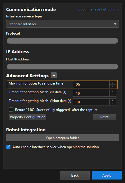
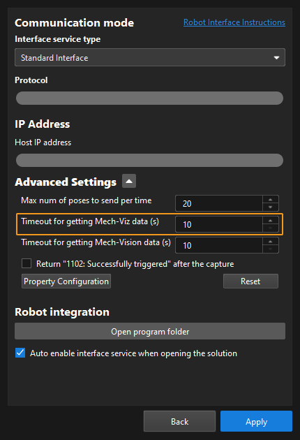
This parameter specifies the number of vision points that the robot side expects to obtain. By default, the vision system sends no more than 20 vision points at a time. Therefore, the maximum default value of this parameter is 20. From the toolbar of Mech-Vision, go to , and you can modify the maximum number of poses to obtain each time. The limit is 30.
Reserved field
This field is not currently in use. The value is 0.
Vision point
Each vision point has 8 data elements The first 6 elements are the TCP, the 7th is the label, and the 8th is the velocity.
-
Tool pose: Robot’s tool center point.
The vision system converts the object pose in the vision point (i.e., output of the “poses” port of the “Procedure Out” Step) to the robot tool pose.
-
Convert the object pose from the form of quaternions to Euler angles.
-
Rotate the object’s pose around the X-axis by 180° to orient its Z-axis downward.
-
-
Label: The label corresponding to a pose (i.e., output of the “labels” port in the “Procedure Out” Step), which is an integer.
-
The label must be an integer-formatted string. If not, add a “Label Mapping” Step BEFORE the “Procedure Out” Step to convert the format of the label to an integer-formatted string.
-
If the “Procedure Out” Step does not have a “labels” port, the value of the “label” parameter is 0.
-
-
Velocity: The value of this parameter is 0 by default.In most cases, vision points output by Mech-Vision do not have information of the object velocity.
Examples
Example 1
-
The robot sends the following command to the vision system.
102, 1 -
The vision system returns the following result after a successful command execution. “1” indicates that one vision point, in total, is obtained.
102, 1100, 1, 1, 0, 95.7806, 644.5677, 401.1013, 91.1206, -171.1301, 180.0, 0, 0The vision system returns the following result after a failed command execution. “1002” indicates that no vision result is obtained.
102, 1002
Example 2
This example illustrates how to obtain 22 vision points.
-
The robot sends Command 101 to the vision system. “0” indicates that the robot is expecting to receive all vision points.
101, 1, 0, 1, -0, -20.6323, -107.8121, -0, -92.8181, 0.0016The vision system returns the following result. “1102” indicates that the Mech-Vision project is successfully triggered.
101, 1102 -
The robot sends Command 102 to the vision system to get 20 vision points.
102, 1The vision system returns the following result to the robot, in which “0” indicates that not all vision points are obtained and “20” indicates that 20 vision points are obtained at this time.
102, 1100, 0, 20, 0, 95.7806, 644.5677, 401.1013, 31.1206, ... -
The robot sends Command 102 to the vision system once more to get the remaining vision points.
102, 1The vision system returns the following data to the robot, in which “1” indicates that all vision points are obtained; and “2” indicates that two vision points are obtained at this time.
102, 1100, 1, 2, 0, 315.2017, 592.1261, 399.6052, 126.1960, ...
Command 103: Switch Mech-Vision Parameter Recipe
Description
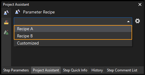
This command triggers Mech-Vision to switch the parameter recipe used by a project. The image below shows how to manually switch the parameter recipe for a Mech-Vision project. For details, refer to the parameter recipe guide.
Calling Sequence
This command should be called BEFORE Command 101.
For details, see “Calling Sequence of Standard Interface Commands”.
Command Format
103, Mech-Vision project ID, parameter recipe ID
Mech-Vision project ID
You can check the ID of a Mech-Vision project in the “Project List” panel. The number before the name of a project is its ID.
Parameter recipe ID
The ID of the parameter recipe in the Mech-Vision project. The ID is a positive integer, from 1 to 99. For details on checking the ID, refer to Parameter Recipe Configuration.
Returned Data Format
103, status code
Status code
Status code 1107 is returned for a successful command execution. For a failed command execution, the specific error code is returned. For details, refer to Status Codes and Troubleshooting.
Examples
-
The robot sends the following command to the vision system to switch the parameter recipe for project No.1 of Mech-Vision to recipe No.2.
103, 1, 2 -
The vision system returns the following result after a successful command execution. “1107” indicates that the parameter recipe of project No.1 in Mech-Vision is successfully switched to recipe No.2.
103, 1107The vision system returns the following result after a failed command execution. “1012” indicates that the specified recipe does not exist.
103, 1012
Command 105: Get Planned Path from Mech-Vision
Description
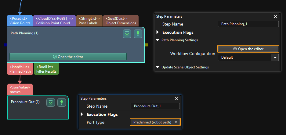
This command obtains the path planned by the Mech-Vision project as a series of waypoints. The path is planned by the path planning tool, which you may enter by clicking Open an Editor as shown in the image below. For details, refer to Path Planning.
| Set the Port Type parameter of the “Procedure Out” Step in Mech-Vision to “Predefined (robot path)”. |
Calling Sequence
This command should be called AFTER Command 101.
For details, see “Calling Sequence of Standard Interface Commands”.
Command Format
105, Mech-Vision project ID, waypoint pose type
Mech-Vision project ID
You can check the ID of a Mech-Vision project in the “Project List” panel. The number before the name of a project is its ID.
Waypoint pose type
This parameter specifies the type of waypoint poses to be obtained.
-
1: Robot’s Joint positions (JPs)
-
2: Tool pose of the robot
Returned Data Format
105, status code, status of transmitting waypoints, number of waypoints, position of “Vision Move” in planned path, waypoint 1 (pose, label, velocity), waypoint 2 (pose, label, velocity), ...
Status code
Status code 1103 is returned for a successful command execution. For a failed command execution, the specific error code is returned. For details, refer to Status Codes and Troubleshooting.
Status of transmitting waypoints
This parameter specifies whether all waypoints are obtained. The value is 0 or 1.
-
0: Not all waypoints are obtained.
-
1: All waypoints are obtained.
|
Number of waypoints
This parameter specifies the number of waypoints that the robot side expects to obtain. By default, the vision system sends no more than 20 waypoints at a time. Therefore, the maximum default value of this parameter is 20. From the toolbar of Mech-Vision, go to , and you can modify the maximum number of poses to obtain each time. The limit is 30.
| BEFORE calling Command 105, set the expected number of vision points or waypoints parameter of Command 101 to 0 to minimize the times of calling Command 105. If the expected number of vision points or waypoints parameter of Command 101 is set to 1, only one waypoint will be obtained each time you call Command 105. You will need to call Command 105 for several times to obtain all waypoints. |
Position of “Vision Move” in planned path
This parameter indicates the position of the Vision Move waypoint corresponding to the “Vision Move” Step of the path planning tool in the entire path. If the path does not contain a “Vision Move” waypoint, the value of this parameter is 0.
If the planned path consists of waypoints “Fixed-Point Move_1, Fixed-Point Move_2, Vision Move, Fixed-Point Move_3” in sequence, then the position of the Vision Move waypoint is 3.
| In the scenario where the robot needs to send this command multiple times to receive the entire path, this parameter has slightly different interpretations in the responses. In the first response, it indicates the position of the Vision Move waypoint in the entire path, while in subsequent responses, this parameter indicates the position of the Vision Move waypoint among the remaining waypoints. |
For example, a path planned by Mech-Vision has four waypoints and the fourth is a Vision Move waypoint.
-
The first time the robot sends the command:
105, 1, 1The vision system returns the following result to the robot. “2” indicates that two waypoints are obtained at this time, and “4” is the position of the Vision Move waypoint in the entire path.
105, 1103, 0, 2, 4, 0.0, 0.0, 0.0, 0.0, 69.0, 0.0, 0, 7, 73.0, 0.0, 0.0, 0.0, 69.0, 0.0, 0, 7 -
The second time the robot sends the command:
105, 1, 1The vision system returns the following result to the robot. The first “2” indicates that the remaining two waypoints are obtained at this time, and the second “2” is the position of the Vision Move waypoint in the entire path.
105, 1103, 1, 2, 2, -77.0, 0.0, 0.0, 0.0, 69.0, 0.0, 0, 7, -26.6781, 55.4142, 45.0133, -7.3735, -10.948, 160.5773, 2, 7
Waypoint
Each waypoint has 8 data elements. The first 6 elements are the pose, the 7th is the label, and the 8th is the velocity.
-
Pose: Robot’s JPs or TCP. The pose type is decided by the waypoint pose type parameter in the command sent by the robot.
-
Label: The label corresponding to a pose (Output of the “labels” port in the “Procedure Out” Step), which is an integer.
-
The label must be a string of numbers. If not, add a “Label Mapping” Step BEFORE the “Procedure Out” Step to convert the data format of the label to a string of numbers.
-
If there is no “labels” port in the “Procedure Out” Step, the value of “label” is 0.
-
-
Velocity: The “Simulation Speed” value in the path planning tool, in the form of percentage.
Examples
-
The robot sends the following command to the vision system to obtain waypoints output by project 1 in Mech-Vision. “2” indicates that the pose type of waypoints is TCP.
105, 1, 2 -
The vision system returns the following result after a successful command execution. The vision system returns all waypoints to the robot, which are 5 in total. The third waypoint is a Vision Move waypoint.
105, 1103, 1, 5, 3, 1030.0, 0, 1260.0, 0.0, 90.0, -0.0, 0, 7, 1149.114, -298.9656, 274.9219, -0.0977, -1.3863, -175.9702, 0, 7, 1149.8416, -296.8585, 245.0048, -0.0977, -1.3863, -175.9702, 2, 7, 1149.114, -298.9656, 274.9219, -0.0977, -1.3863, -175.9702, 0, 7, 1030.0, 0, 1260.0, 0.0, 90.0, -0.0, 0,7The vision system returns the following result after a failed command execution. “1020” indicates that the Mech-Vision project is not started.
105, 1020
Command 106: Get Gripper DO List from Mech-Vision
Description
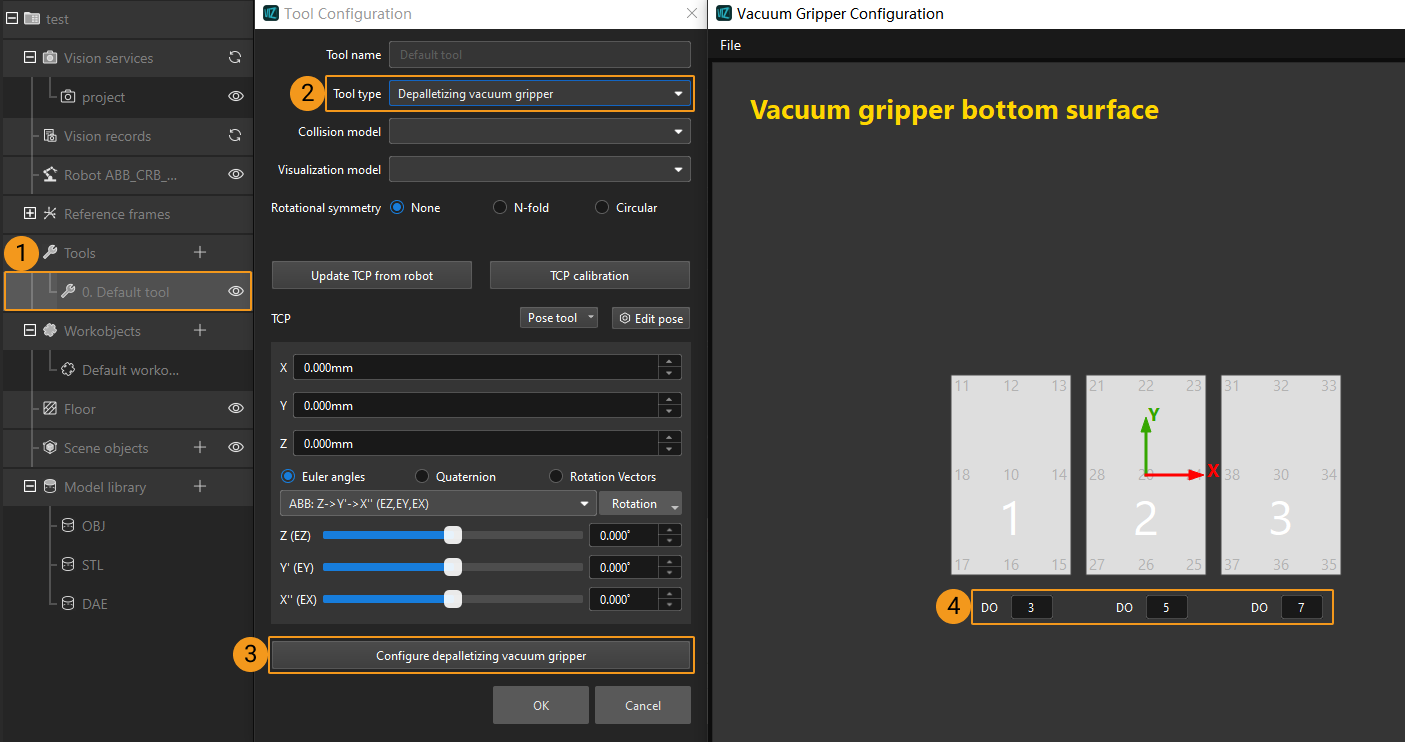
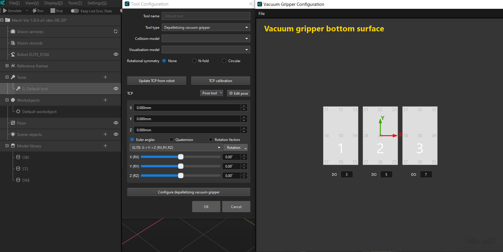
This command obtains the control signal list for the multi-section vacuum gripper from the Mech-Vision project. You should configure DO signals BEFORE calling this command.
Select the “Path Planning” Step and then click Open and Editor in the Step Parameters panel. Double-click the name of the robot tool. In the pop-out window, select Depalletizing vacuum gripper for Tool type, and click Configure depalletizing vacuum gripper. Then, configure DO signals according to needs.
Calling Sequence
This command should be called AFTER Command 100, Command 105 or Command 111.
For details, see “Calling Sequence of Standard Interface Commands”.
Command Format
106, Mech-Vision project ID
Mech-Vision project ID
You can check the ID of a Mech-Vision project in the “Project List” panel. The number before the name of a project is its ID.
Returned Data Format
106, status code, DO signal 1, DO signal 2, ..., DO signal 64
Status code
Status code 1106 is returned for a successful command execution. For a failed command execution, the specific error code is returned. For details, refer to Status Codes and Troubleshooting.
DO signal
This command returns 64 DO signals. The valid DO signal is a non-negative integer, ranging from 0 to 999. “-1” is an invalid DO signal that serves as a placeholder.
For example, valid DO signals in the table below are 1, 3, 5, and 6, instructing the robot to set the value of these DO signals to “ON”.
1st |
2nd |
3rd |
4th |
5th |
6th |
7th |
8th |
… |
63rd |
64th |
1 |
3 |
5 |
6 |
-1 |
-1 |
-1 |
-1 |
… |
-1 |
-1 |
Examples
-
The robot sends the following command to the vision system.
106, 1 -
The vision system returns the following result. Valid DO signals are 11 and 12.
106, 1106, 11, 12, -1, -1, -1, -1, -1, -1, -1, -1, -1, -1, -1, -1, -1, -1, -1, -1, -1, -1, -1, -1, -1, -1, -1, -1, -1, -1, -1, -1, -1, -1, -1, -1, -1, -1, -1, -1, -1, -1, -1, -1, -1, -1, -1, -1, -1, -1, -1, -1, -1, -1, -1, -1, -1, -1, -1, -1, -1, -1, -1, -1, -1, -1
Command 110: Get Custom Output Data from Mech-Vision
Description
This command obtains data from the custom port(s) of the “Procedure Out” Step in Mech-Vision. Select the “Procedure Out” Step and click Open an Editor to enter the settings window of custom ports. The “Customized Keys” panel displays custom port names, such as “customeData1” and “customeData2” in the image below.
|
Calling Sequence
This command should be called AFTER Command 101.
For details, see “Calling Sequence of Standard Interface Commands”.
Command Format
110, Mech-Vision project ID
Mech-Vision project ID
You can check the ID of a Mech-Vision project in the “Project List” panel. The number before the name of a project is its ID.
Returned Data Format
110, status code, status of transmitting vision points, number of elements in custom output data (N), pose, label, element 1 in custom output data, ..., element N in custom output data
Status code
Status code 1100 is returned for a successful command execution. For a failed command execution, the specific error code is returned. For details, refer to Status Codes and Troubleshooting.
Status of transmitting vision points
This parameter specifies whether all vision points are obtained. The value is 0 or 1.
-
0: Not all vision points are obtained.
-
1: All vision points are obtained.
|
Number of elements in custom output data
The total number of elements in data output by all custom ports. For example, outputs of the ports of the “Procedure Out” Step are presented in the following table. “customData1” and “customData2” are custom ports, with 3 and 2 columns in their respective output data. Therefore, the number of elements in custom output data is 5, which is the result of adding 3 and 2.
Port name |
poses |
labels |
customData1 |
customData2 |
Output |
[ [0, 0, 0, 1, 0, 0, 0], [0, 0, 0, 1, 0, 0, 0] ] |
[ "0", "1" ] |
[ [0, 0, 1], [1, 0, 0] ] |
[ [0, 0], [1, 1] ] |
Number of rows (i.e. number of items in the list) |
2 |
2 |
2 |
2 |
Number of columns (i.e. number of elements in each item) |
7 |
1 |
3 |
2 |
Pose
This parameter specifies the robot tool pose corresponding to one vision point. The vision system converts the object pose in the vision point (namely, output of the “poses” port of the “Procedure Out” Step) to the robot tool pose. The process is as follows.
-
Convert the object pose from the form of quaternions to Euler angles.
-
Rotate the object’s pose around the X-axis by 180° to orient its Z-axis downward.
Label
The label of one vision point that is output by the “labels” port of the “Procedure Out” Step.
|
Element in custom output data
“Elements in custom output data” are data output by all custom ports concerning one vision point. The total number is specified by the number of elements in custom output data parameter. For example, data output from ports of the “Procedure Out” Step is presented in the following table. The elements in custom output data of the first vision point are [0, 0, 1] and [0, 0]; and the elements in custom output data of the second vision point are [1, 0, 0] and [1, 1].
Port name |
poses |
labels |
customData1 |
customData2 |
Port data |
[ [0, 0, 0, 1, 0, 0, 0], [0, 0, 0, 1, 0, 0, 0] ] |
[ "0", "1" ] |
[ [0, 0, 1], [1, 0, 0] ] |
[ [0, 0], [1, 1] ] |
The first vision point |
[0, 0, 0, 1, 0, 0, 0] |
0 |
[0, 0, 1] |
[0, 0] |
The second vision point |
[0, 0, 0, 1, 0, 0, 0] |
1 |
[1, 0, 0] |
[1, 1] |
| The custom port outputs are arranged in the alphabetical order of the names of custom ports. |
Examples
Assume that the output of ports of the “Procedure Out” Step in the Mech-Vision project is as shown in the image below. The steps to obtain output data from the custom port(s) using Command 101 and Command 110 are as follows.

-
The robot sends Command 101 to the vision system to obtain all vision points, that is, two in total.
101, 1, 0, 0The vision system returns the following result, indicating that Command 101 is successfully executed.
101, 1102 -
The robot sends Command 110 to the vision system to obtain all data of the first vision point.
110, 1The vision system returns the following result, in which 11 and 21 are elements in custom output data.
110, 1100, 0, 2, 1150.1272, -297.2476, -55.0715, -0.1087, -1.6156, -176.1518, 1, 11, 21 -
Then, the robot sends Command 110 to the vision system to obtain all data of the second vision point.
110, 1The vision system returns the following result to the robot. “1” indicates that all vision points are obtained. “12” and “22” are elements in custom output data.
110, 1100, 1, 2, 592.6891, -256.7424, -56.6007, 0.0723, 1.1348, -176.355, 2, 12, 22
Command 111: Get Vision Move Data from Mech-Vision
Description
This command obtains Vision Move data from the Mech-Vision project. “Vision Move data” refers to data output by the Vision Move Step in the path planning tool, which you may enter from the Path Planning Step. Vision Move data includes labels of picked workobjects, number of picked workobjects, number of workobjects to be picked this time, edge/corner ID of vacuum gripper, TCP offset, orientation of workobject group, orientation of workobject, dimensions of workobject group.
Command Format
111, Mech-Vision project ID, waypoint pose type
Mech-Vision project ID
You can check the ID of a Mech-Vision project in the “Project List” panel. The number before the name of a project is its ID.
Waypoint pose type
This parameter specifies the type of waypoint poses to be obtained.
-
1: Robot’s Joint positions (JPs)
-
2: Tool pose of the robot
Returned Data Format
111, status code, status of transmitting waypoints, waypoint type, pose, motion type, tool ID, Vision Move data
Status code
Status code 1103 is returned for a successful command execution. For a failed command execution, the specific error code is returned. For details, refer to Status Codes and Troubleshooting.
Status of transmitting waypoints
This parameter specifies whether all waypoints are obtained. The value is 0 or 1.
-
0: Not all waypoints are obtained.
-
1: All waypoints are obtained.
|
Waypoint type
Value |
Waypoint type |
Returned data |
0 |
Non-Vision Move waypoint |
Pose, motion type, tool ID, velocity |
1 |
Vision Move waypoint |
Pose (TCP), motion type, tool ID, velocity, Vision Move data |
Pose
The pose of a waypoint can be robot’s joint positions or TCP, depending on the value of the waypoint pose type parameter in the command sent by the robot.
Motion type
-
1: joint motion (MOVEJ)
-
2: linear motion (MOVEL)
Tool ID
The ID of the tool to be used at this waypoint. The value “-1” means that no tool will be used at this waypoint.
Velocity
The “Simulation Speed” value in the path planning tool, in the form of percentage.
Vision Move data
Vision Move data includes the following information.
| Name | Description | Number of elements |
|---|---|---|
Labels of picked workobjects |
Consists of 10 integers. By default, its value is ten 0s. |
10 |
Number of picked workobjects |
The total number of workobjects that have been picked. |
1 |
Number of workobjects to be picked this time |
The number of workobjects to be picked this time. |
1 |
Edge/corner ID of vacuum gripper |
The ID of the edge/corner used to pick workobjects this time. |
1 |
TCP offset |
The XYZ offset between the center of the workobject group and the tool pose center. |
3 |
Orientation of workobject group |
The relative position between the workobject group and the length of the vacuum gripper. The value is 0 or 1, where 0 stands for parallel and 1 for vertical. |
1 |
Orientation of workobject |
The relative position between the length of a workobject and that of the vacuum gripper. The value is 0 or 1, where 0 stands for parallel and 1 for vertical. |
1 |
Dimensions of workobject group |
The length, width and height of the workobject group to be picked this time. |
3 |
Examples
-
The robot sends the following command to the vision system.
111, 1, 2 -
The vision system returns the following result to the robot.
Parameter Value Command number
111
Status code
1103
Status of transmitting waypoints
1
Waypoint type
1
Pose
95.7806, 644.5677, 401.1013, 91.1206, -171.1301, 180.0
Motion type
1
Tool ID
0
Velocity
55
Vision Move data
Labels of picked workobjects
1, 1, 1, 0, 0, 0, 0, 0, 0, 0
Number of picked workobjects
100
Number of workobjects to be picked this time
3
Edge/corner ID of vacuum gripper
28
TCP offset
95.7806, 644.5677, 0
Orientation of workobject group
0
Orientation of workobject
0
Dimensions of the workobject group
600, 800, 300
Command 200: Trigger Mech-Viz Project and Get Planned Path
Description
This command triggers the following operations in sequence: First, it triggers the Mech-Viz project. Second, it sets the Exit port for the Branch by Msg Step (which is skipped if the project does not have a branch). Third, it gets the planned path from the Mech-Viz project.
| If the Mech-Viz project has more than one “Branch by Msg” Step, Command 200 will not work. |
Command Format
200, Branch by Msg Step ID, exit port, waypoint pose type, robot joint positions, robot flange pose
Branch by Msg Step ID
This parameter specifies the Step ID of the “Branch by Msg” Step. The value is a positive integer.
| Set this parameter to 0 if the Mech-Viz project doesn’t have a “Branch by Msg” Step. |
Exit port
This parameter specifies the exit port of the “Branch by Msg” Step. The value is a positive integer. When the parameter value is set to “N”, the Mech-Viz project exits from the port with an ID of “N-1” of the “Branch by Msg” Step. For example, when the robot sends “200, 2, 1, …” to the vision system, the Mech-Viz project takes port 0 as the exit of the Branch by Msg Step with a Step ID of 2.
| Set this parameter to 0 if the Mech-Viz project doesn’t have a “Branch by Msg” Step. |
Waypoint pose type
This parameter specifies the type of waypoint poses to be obtained.
-
1: Robot’s Joint positions (JPs)
-
2: Tool pose of the robot
Robot joint positions & robot flange pose
Robot sends its current joint positions and flange pose to the Mech-Viz project.
Returned Data Format
200, status code, status of transmitting waypoints, number of waypoints, position of “Vision Move” in planned path, waypoint 1 (pose, label, velocity), waypoint 2 (pose, label, velocity), ...
Status code
Status code 2100 is returned for a successful command execution. For a failed command execution, the specific error code is returned. For details, refer to Status Codes and Troubleshooting.
Status of transmitting waypoints
This parameter specifies whether all waypoints are obtained. The value is 0 or 1.
-
0: Not all waypoints are obtained.
-
1: All waypoints are obtained.
|
Number of waypoints
This parameter specifies the number of waypoints that the robot side expects to obtain.
Position of “Vision Move” in planned path
This parameter specifies the position of the Vision Move waypoint (i.e., the waypoint corresponding to the “Vision Move” Step in the Mech-Viz project) in the planned path. If the path does not contain a “Vision Move” waypoint, the value of this parameter is 0.
If the planned path consists of waypoints “Fixed-Point Move_1, Fixed-Point Move_2, Vision Move, Fixed-Point Move_3” in sequence, then the position of “Vision Move” is 3.
Waypoint
Each waypoint has 8 data elements. The first 6 elements are the pose, the seventh is the label, and the eighth is the velocity.
-
Pose: Robot’s tool pose or joint positions (JPs). The pose type is decided by the waypoint pose type parameter in the command sent by the robot.
-
Label: The label corresponding to a pose (output of the “labels” port in the “Procedure Out” Step), which is an integer.
-
The label should be an integer-formatted string. If not, add a “Label Mapping” Step BEFORE the “Procedure Out” Step to convert the format of the label to an integer-formatted string.
-
If the “Procedure Out” Step does not have a “labels” port, the value of the label parameter is 0.
-
-
Velocity: The value set for the move-type Steps, in percentage.
Examples
-
The robot sends the following command to the vision system. This command triggers the Mech-Viz project to run, and the project takes port 2 as the exit of the Branch by Msg Step whose Step ID is 5. “1” indicates that the robot expects to receive poses of waypoints from the Mech-Viz project in the form of joint positions. This command also specifies the robot’s current joint positions and flange pose.
200, 5, 3, 1, 5.18, 14.52, 4.03, 0.09, 72.44, 5.15, 549.56, 50.0, 647.01, 180.0, -1.0, 180.0 -
The vision system returns the following result after a successful command execution. The vision system returns all waypoints to the robot, which are two in total. The second waypoint is a Vision Move waypoint.
200, 2100, 1, 2, 2, 8.3077, 15.1634, -142.1778, -2.7756, -31.4404, -96.9490, 0, 64, 8.2425, 12.1301, -141.7587, -2.5135, -34.8905, -97.1911, 0, 32
Command 201: Trigger Mech-Viz Project
Description
This command starts the Mech-Viz project to run. Mech-Viz plans the robot’s motion path based on the vision result output by Mech-Vision.
| Right-click the project name in the “Resources” panel in Mech-Viz and select Autoload Project. |
Calling Sequence
You should set Step Parameters BEFORE starting a Mech-Viz project. Therefore, call Command 207 or Command 208 BEFORE calling Command 201.
For details, see “Calling Sequence of Standard Interface Commands”.
Command Format
201, robot pose type, robot pose
Robot pose type & robot pose
-
Robot pose type specifies the type of the pose of the real robot to be input to the Mech-Viz project. The value range is 0 to 2.
-
The value of the robot pose type parameter specifies what robot pose will be sent to the vision system.
The following table explains the relationship between the two parameters.
| Robot pose type | Robot pose | Description | Applicable scenario |
|---|---|---|---|
0 |
0, 0, 0, 0, 0, 0 |
The robot will not send its pose to the Mech-Viz project. The simulated robot in Mech-Viz moves from the initial pose (JPs = [0, 0, 0, 0, 0, 0]) to the first waypoint. |
The camera mounting method is Eye To Hand. |
1 |
Robot’s current JPs and flange pose |
The robot sends its current joint positions and flange pose to the Mech-Viz project. The simulated robot in Mech-Viz moves from the input JPs to the first waypoint. |
This setting is recommended when the camera is mounted in the Eye In Hand method. |
2 |
JPs customized by the robot side |
The robot sends the JPs of a teaching point, instead of the current JPs, to the Mech-Viz project. The Mech-Viz project uses the JPs to plan the next path in advance while the robot is not in the camera capture region, as shown below. The simulated robot in Mech-Viz moves from the input joint positions to the first waypoint. |
This setting is recommended when the camera is mounted in the Eye To Hand method. |
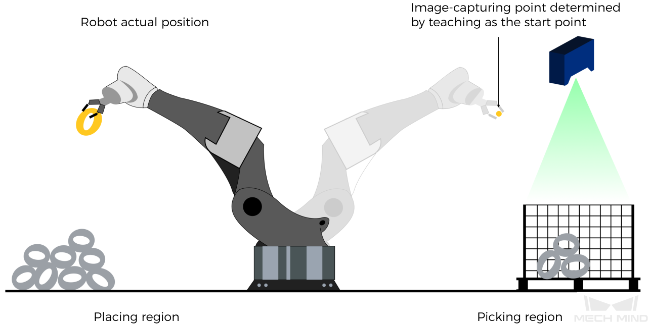
Why robot pose type 2 is recommended when the camera is mounted in the Eye To Hand method?
In the Eye To Hand method, the camera can perform image capturing for the next round of path planning before the robot returns to the image capture region and picking region, thus shortening the cycle time. The image below demonstrates how a robot works in the placing region.
If robot pose type is set to 1, the robot will send the current pose to Mech-Viz. It is possible that the real robot moves to other positions before reaching the first waypoint. However, the simulated robot moves directly to the first waypoint from the pose sent by the robot. Consequently, there may be a mismatch between the paths of the real robot and simulated robot. This mismatch can potentially lead to unpredicted safety hazards, especially if collision is detected in the path of the simulated robot.
On the other hand,if robot pose type is set to 2, the robot will send the image-capturing pose set by teaching to Mech-Viz. Thus, the real robot can trigger the next round of path planning in Mech-Viz when the real robot is in the image-capturing region and the cycle time can be shortened.
In conclusion, robot pose type should be set to 2 for projects in the Eye To Hand method.
Returned Data Format
201, status code
Status code
Status code 2103 is returned for a successful command execution. For a failed command execution, the specific error code is returned. For details, refer to Status Codes and Troubleshooting.
Examples
Example 1
-
In an Eye In Hand scenario, the robot sends the following command to the vision system. “1” indicates that the robot is sending its current joint positions and flange pose.
201, 1, 5.18, 14.52, 4.03, 0.09, 72.44, 5.15, 549.56, 50.0, 647.01, 180.0, -1.0, 180.0 -
The vision system returns the following result. “2103” indicates that the Mech-Viz project is successfully triggered.
201, 2103
Example 2
-
In an Eye To Hand scenario, the robot sends the following command to the vision system. “2” indicates that the robot is sending the joint positions of the teaching point.
201, 2, 5.18, 14.52, 4.03, 0.09, 72.44, 5.15 -
The vision system returns the following result. “2103” indicates that the Mech-Viz project is successfully triggered.
201, 2103
Command 202: Stop Mech-Viz Project
Calling Sequence
This command should be called AFTER Command 201.
For details, see “Calling Sequence of Standard Interface Commands”.
Returned Data Format
202, status code
Status code
Status code 2104 is returned for a successful command execution. For a failed command execution, the specific error code is returned. For details, refer to Status Codes and Troubleshooting.
Command 203: Set Exit Port for Branch by Msg in Mech-Viz
Description
This command sets the exit port for the “Branch by Msg” Step. When the next Step is a “Branch by Msg” Step, the Mech-Viz project will wait for this command to specify the exit port.
Calling Sequence
This command should be called AFTER Command 201.
For details, see “Calling Sequence of Standard Interface Commands”.
Command Format
203, Step ID, exit port
Step ID
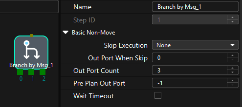
This parameter specifies the Step ID of the “Branch by Msg” Step. The value is a positive integer. The Step ID is displayed in the Step parameter panel. For example, the Step ID of the Step in the image above is 1.
Exit port
This parameter specifies the exit port of the “Branch by Msg” Step. The value is a positive integer. When the parameter value is set to “N”, the Mech-Viz project exits from the port with an ID of “N-1” of the “Branch by Msg” Step. For example, when the robot sends “203, 2, 1” to the vision system, the Mech-Viz project takes port 0 as the exit of the Branch by Msg Step with a Step ID of 2.
Returned Data Format
203, status code
Status code
Status code 2105 is returned for a successful command execution. For a failed command execution, the specific error code is returned. For details, refer to Status Codes and Troubleshooting.
Examples
-
The robot sends the following command to the vision system. “5” is the Step ID, and “3” indicates that the Mech-Viz project exits from port 2 of the “Branch by Msg” Step.
203, 5, 3 -
The vision system returns the following result to the robot. “2105” indicates that the exit port of the Branch by Msg Step is set successfully.
203, 2105
204: Set Current Index for Mech-Viz
Description
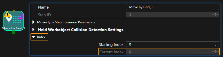
This command sets the value of the Current Index parameter of index-type Steps. Steps that have the “Index” parameter include “Move by Grid”, “Move by List”, “Custom Pallet Pattern”, “Predefined Pallet Pattern”, etc.
Calling Sequence
Index-type Steps are often preceded by a “Branch by Msg” Step. The robot should call commands in this order: Command 201, Command 204, and Command 203. This is to ensure that Mech-Viz has enough time to set the Current Index value.
For details, see “Calling Sequence of Standard Interface Commands”.
Command Format
204, Step ID, Current Index
Step ID
This parameter specifies the Step ID of the Index-type Step. The value is a positive integer. The Step ID is displayed in the Step parameter panel. For example, the Step ID of the Step in the image above is 3.
Current Index
This parameter specifies the Current Index for a Index-type Step. The value is a positive integer. When this parameter value is set to “N”, the Current Index of the corresponding Step is “N-1”. For example, when the robot sends “204, 2, 1” to the vision system, the Current Index of the Step with an ID of 2 is set to 0.
Returned Data Format
204, status code
Status code
Status code 2106 is returned for a successful command execution. For a failed command execution, the specific error code is returned. For details, refer to Status Codes and Troubleshooting.
Examples
-
The robots sends the following command to the vision system. “2” is the Step ID, and “6” indicates that the Current Index of the corresponding Step is set to “5”.
204, 2, 6 -
The vision system returns the following result. “2106” indicates that the Current Index is successfully set.
204, 2106
Command 205: Get Planned Path from Mech-Viz
Description
This command obtains the path planned by the Mech-Viz project as a series of waypoints.
|
Waypoint: Each point that the robot reaches when moving along the planned path. A waypoint has information including the robot pose, label, move type, velocity, etc. Waypoints can be divided into two categories:
|
Calling Sequence
This command should be called AFTER Command 201.
For details, see “Calling Sequence of Standard Interface Commands”.
Command Format
205, waypoint pose type
Waypoint pose type
This parameter specifies the type of waypoint poses to be obtained.
-
1: Robot’s Joint positions (JPs)
-
2: Tool pose of the robot
Returned Data Format
205, status code, status of transmitting waypoints, number of waypoints, position of “Vision Move” in planned path, waypoint 1 (pose, label, velocity), waypoint 2 (pose, label, velocity), ...
Status code
Status code 2100 is returned for a successful command execution. For a failed command execution, the specific error code is returned. For details, refer to Status Codes and Troubleshooting.
Status of transmitting waypoints
This parameter specifies whether all waypoints are obtained. The value is 0 or 1.
-
0: Not all waypoints are obtained.
-
1: All waypoints are obtained.
|
Number of waypoints
This parameter specifies the number of waypoints that the robot side expects to obtain. By default, the vision system sends no more than 20 waypoints at a time. Therefore, the maximum default value of this parameter is 20. From the toolbar of Mech-Vision, go to , and you can modify the maximum number of poses to obtain each time. The limit is 30.
Position of “Vision Move” in planned path
This parameter specifies the position of the Vision Move waypoint (i.e., the waypoint corresponding to the “Vision Move” Step in the Mech-Viz project) in the planned path. If the path does not contain a “Vision Move” waypoint, the value of this parameter is 0.
If the planned path consists of waypoints “Fixed-Point Move_1, Fixed-Point Move_2, Vision Move, Fixed-Point Move_3” in sequence, then the position of “Vision Move” is 3.
| In the scenario where the robot needs to send this command multiple times to receive the entire path, this parameter has slightly different interpretations in the responses. In the first response, it indicates the position of the Vision Move waypoint in the entire path, while in subsequent responses, this parameter indicates the position of the Vision Move waypoint among the remaining waypoints. |
For example, a path planned by Mech-Viz has four waypoints and the fourth is a Vision Move waypoint.
-
The first time the robot sends the command:
205, 1The vision system returns the following result to the robot. “2” indicates that two waypoints are obtained at this time, and “4” is the position of the Vision Move waypoint in the entire path.
205, 2100, 0, 2, 4, 0.0, 0.0, 0.0, 0.0, 69.0, 0.0, 0, 7, 73.0, 0.0, 0.0, 0.0, 69.0, 0.0, 0, 7 -
The second time the robot sends the command:
205, 1The vision system returns the following result to the robot. The first “2” indicates that the remaining two waypoints are obtained at this time, and the second “2” is the position of the Vision Move waypoint in the entire path.
205, 2100, 1, 2, 2, -77.0, 0.0, 0.0, 0.0, 69.0, 0.0, 0, 7, -26.6781, 55.4142, 45.0133, -7.3735, -10.948, 160.5773, 2, 7
Waypoint
Each waypoint has 8 data elements. The first 6 elements are the pose, the seventh is the label, and the eighth is the velocity.
-
Pose: Robot’s tool pose or joint positions (JPs). The pose type is decided by the waypoint pose type parameter in the command sent by the robot.
-
Label: The label corresponding to a pose (output of the “labels” port in the “Procedure Out” Step), which is an integer.
-
The label should be an integer-formatted string. If not, add a “Label Mapping” Step BEFORE the “Procedure Out” Step to convert the format of the label to an integer-formatted string.
-
If the “Procedure Out” Step does not have a “labels” port, the value of the label parameter is 0.
-
-
Velocity: The value set for the move-type Steps, in percentage.
Examples
-
The robot sends the following command to the vision system to obtain the waypoints output by the Mech-Viz project in the form of JPs.
205, 1 -
The vision system returns the following result after a successful command execution. The vision system returns all waypoints to the robot, which are two in total. The second waypoint is a Vision Move waypoint.
205, 2100, 1, 2, 2, 8.3077, 15.1634, -142.1778, -2.7756, -31.4404, -96.9490, 0, 64, 8.2425, 12.1301, -141.7587, -2.5135, -34.8905, -97.1911, 0, 32
Command 206: Get Gripper DO List
Description
This command obtains the control signal list for the multi-section vacuum gripper from the Mech-Viz project. BEFORE calling this command, users should configure DO signals and the “Set DO” Step.
-
In Mech-Viz, double-click the tool name. Select Depalletizing vacuum gripper for Tool type, and click Configure depalletizing vacuum gripper. Then, configure the DO signal value according to needs.
-
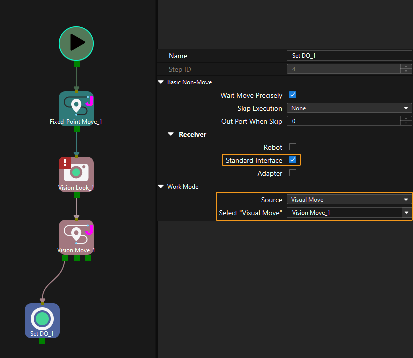
Configure the “Set DO” Step
-
The “Set DO” Step should be AFTER the “Vision Move” Step.
-
Select Standard Interface for Receiver.
-
In the Work Mode area, select Visual Move for the Source parameter, and select the “Vision Move” Step that the “Set DO” Step is connected to for the Select “Vision Move” parameter. In the image below, “Vision Move_1” is selected.
-
Calling Sequence
This command should be called AFTER Command 200,Command 205 or Command 210.
For details, see “Calling Sequence of Standard Interface Commands”.
Returned Data Format
206, status code, DO signal 1, DO signal 2, ..., DO signal 64
Status code
Status code 2102 is returned for a successful command execution. For a failed command execution, the specific error code is returned. For details, refer to Status Codes and Troubleshooting.
DO signal
This command returns 64 DO signals. The valid DO signal is a non-negative integer, ranging from 0 to 999. “-1” is an invalid DO signal that serves as a placeholder.
For example, valid DO signals in the table below are 1, 3, 5, and 6, instructing the robot to set the value of these DO signals to “ON”.
1st |
2nd |
3rd |
4th |
5th |
6th |
7th |
8th |
… |
63rd |
64th |
1 |
3 |
5 |
6 |
-1 |
-1 |
-1 |
-1 |
… |
-1 |
-1 |
Examples
-
The robot sends the following command to the vision system.
206 -
The vision system returns the following result. Valid DO signals are 11 and 12.
206, 2102, 11, 12, -1, -1, -1, -1, -1, -1, -1, -1, -1, -1, -1, -1, -1, -1, -1, -1, -1, -1, -1, -1, -1, -1, -1, -1, -1, -1, -1, -1, -1, -1, -1, -1, -1, -1, -1, -1, -1, -1, -1, -1, -1, -1, -1, -1, -1, -1, -1, -1, -1, -1, -1, -1, -1, -1, -1, -1, -1, -1, -1, -1, -1, -1
Command 207: Read Mech-Viz Step Parameter
Calling Sequence
This command should be called BEFORE Command 201.
For details, see “Calling Sequence of Standard Interface Commands”.
Command Format
207, Config ID
Config ID
This parameter corresponds to the Config ID field defined in the property_config file.
|
From the toolbar of Mech-Vision, go to . Click Property Configuration to open the property_config file. 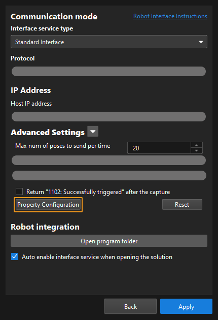
|
Before sending this command, users should define a Config ID and its corresponding Step ID and parameter key name in the format as shown below in the property_config file.
read, Config ID, Step ID, parameter key name
read |
Indicates that this line is to read a parameter value of a Step. |
Config ID |
Specifies a unique ID, which is a positive integer. One Config ID corresponds to only one parameter value of a Step. To read multiple parameter values, you should set different Config IDs. |
Step ID |
Specifies the Step whose parameter value the robot requires to read. |
Parameter key name |
Specifies the key name of the parameter whose value the robot requires to read. |
|
In the line below, “5” is the Config ID; “3” is the Step ID; xCount is the parameter key name. Add this line to the property_config file. When the robot sends “207, 5”, it receives the value of the parameter whose key name is xCount.
read, 5, 3, xCount|
The property_config file can have multiple read commands. The Config ID in these commands must be different. |
Returned Data Format
207, status code, Step parameter value
Status code
Status code 2109 is returned for a successful command execution. For a failed command execution, the specific error code is returned. For details, refer to Status Codes and Troubleshooting.
Step parameter value
The value of the Step parameter that the robot requires to read.
|
Examples
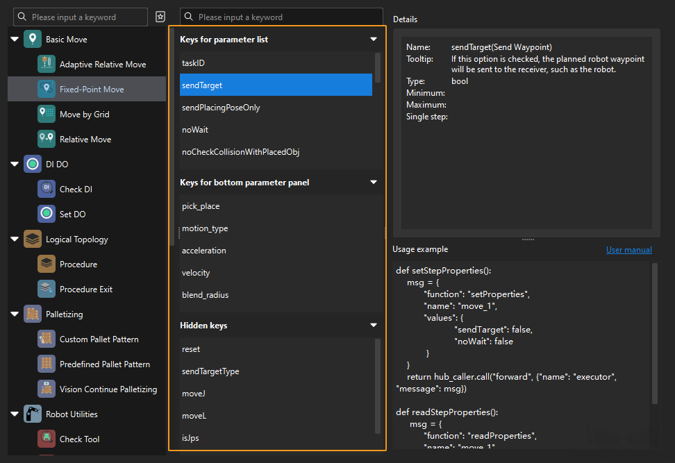
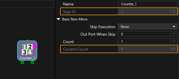
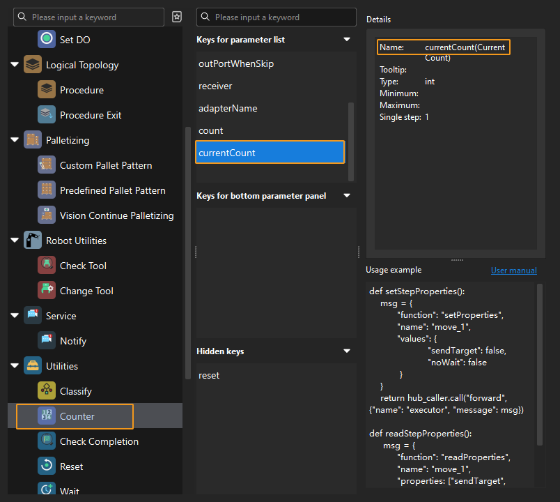
This example shows how to read the Current Count parameter value of the “Counter” Step with a Step ID of 1.
-
Check the key name of the Current Count parameter in the Key Query Tool. The key name is currentCount.
-
Write the following line to the property_config file and save the file. The Config ID is 10 and it cannot be repeatedly used in different “read” lines. The Step ID of the “Counter” Step is 1. The key name of the Current Count parameter is currentCount.
read, 10, 1, currentCount -
Restart the interface service on the toolbar of Mech-Vision.
-
The robot sends the following command to the vision system. The Config ID is 10.
207, 10 -
The vision system returns the following result. “0” is the value of the Current Count parameter whose key name is currentCount.
207, 2109, 0
Command 208: Set Mech-Viz Step Parameter
Calling Sequence
This command should be called BEFORE Command 201.
For details, see “Calling Sequence of Standard Interface Commands”.
Command Format
208, Config ID
Config ID
This parameter corresponds to the Config ID field defined in the property_config file.
|
From the toolbar of Mech-Vision, go to . Click Property Configuration to open the property_config file.
|
Before sending this command, users should define a Config ID and its corresponding Step ID, parameter key name and parameter value in the following format in the property_config file.
write, Config ID, Step ID, parameter key name, parameter value
write |
Indicates that this line is used to set the parameter value of a Step. |
Config ID |
Specifies an ID, which is a positive integer and can be used repeatedly. |
Step ID |
Specifies the Step whose parameter value the robot requires to set. |
Parameter key name |
Specifies the key name of the parameter whose value the robot requires to set. |
Parameter value |
Specifies the value that the robot sets for the parameter. |
|
In the line below, “6” is the Config ID; “3” is the Step ID; xOffset is the parameter key name; 0.000000 is the value of the parameter you set. Add this line to the property_config file. When the robot sends “208, 6”, the vision system sets the value of the parameter whose key name is xOffset to 0.000000.
write, 6, 3, xOffset, 0.000000|
The property_config file can contain multiple “write” commands with the same Config ID. In other words, one Config ID can be used to set values for several parameters. In the example below, when the robot sends “208, 1”, the vision system sets the values of the parameters whose key names are xOffset, yOffset and zOffset respectively to 0.000000, 1.000000, and 2.000030. |
Returned Data Format
208, status code
Status code
Status code 2108 is returned for a successful command execution. For a failed command execution, the specific error code is returned. For details, refer to Status Codes and Troubleshooting.
Examples
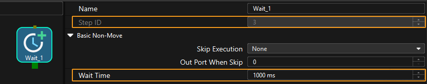
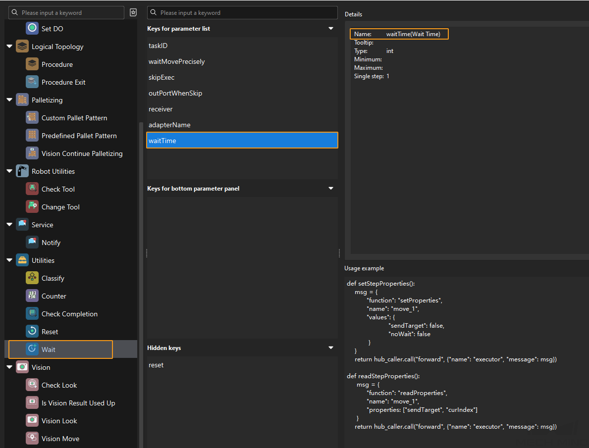
This example illustrates how to set the value of the Wait Time parameter. In this example, the Step ID of the “Wait” Step is 3.
-
Check the key name of the Wait Time parameter in the Key Query Tool. The parameter key name is waitTime.
-
Write the line below to the property_config file and save the file. The Config ID is 11. The Step ID of the “Wait” Step is 3. waitTime is the key name of the Wait Time parameter. The value set for the “Wait Time” parameter is 1000.
write, 11, 3, waitTime, 1000 -
Restart the interface service on the toolbar of Mech-Vision.
-
The robot sends the following command to the vision system. The Config ID 11.
208, 11 -
The vision system returns the following result. “2108” indicates that the value is successfully set.
208, 2108
Command 210: Get Vision Move Data or Custom Output Data from Mech-Viz
Description
This command obtains data output by the Vision Move Step or the custom port(s) of the “Procedure Out” Step from the Mech-Viz project.
-
Vision Move data: Refers to data output by the “Vision Move” Step in Mech-Viz, including the labels of picked workobjects, number of picked workobjects, number of workobjects to be picked this time, edge/corner ID of vacuum gripper, TCP offset, orientation of workobject group, orientation of workobject, dimensions of workobject group.
-
Custom output data: Refers to data output by the custom-type port(s) of the “Procedure Out” Step in Mech-Vision and then forwarded by Mech-Viz. Select the “Procedure Out” Step and click Open an Editor to enter the settings window of custom ports. The “Customized Keys” panel displays custom port names, such as “customeData1” and “customeData2” in the image below.
|
Command Format
210, returned data format
Returned data format
Value |
Explanation (For details, see the Returned Data Format section below. If the Mech-Vision project does not have a custom port, no element of custom output data will be returned.) |
|
Waypoint type |
Returned data |
|
1 |
Non-Vision Move waypoint |
Pose (JPs), motion type, tool ID, velocity |
Vision Move waypoint |
Pose (JPs), motion type, tool ID, velocity, number of elements in custom output data (N), element 1 in custom output data, ..., element N in custom output data |
|
2 |
Non-Vision Move waypoint |
Pose (TCP), motion type, tool ID, velocity |
Vision Move waypoint |
Pose (TCP), motion type, tool ID, velocity, number of elements in custom output data (N), element 1 in custom output data, ..., element N in custom output data |
|
3 |
Non-Vision Move waypoint |
Pose (JPs), motion type, tool ID, velocity |
Vision Move waypoint |
Pose (JPs), motion type, tool ID, velocity, Vision Move data, number of elements in custom output data (N), element 1 in custom output data, ..., element N in custom output data |
|
4 |
Non-Vision Move waypoint |
Pose (TCP), motion type, tool ID, velocity |
Vision Move waypoint |
Pose (TCP), motion type, tool ID, velocity, Vision Move data, number of elements in custom output data (N), element 1 in custom output data, ..., element N in custom output data |
|
| When this command is used to obtain Vison Move waypoint, Vision Move data or custom port output will be returned, which, in contrast, will not be returned when Command 205 is sent to obtain Vision Move waypoint. |
Returned Data Format
210, status code, status of transmitting waypoints, waypoint type, pose, motion type, tool ID, velocity, Vision Move data, number of elements in custom output data (N), element 1 in custom output data,..., element N in custom output data
|
Status code
Status code 2100 is returned for a successful command execution. For a failed command execution, the specific error code is returned. For details, refer to Status Codes and Troubleshooting.
Status of transmitting waypoints
This parameter specifies whether all waypoints are obtained. The value is 0 or 1.
-
0: Not all waypoints are obtained.
-
1: All waypoints are obtained.
|
Waypoint type
Value |
Waypoint type |
Data |
0 |
Non-Vision Move waypoint |
Pose, motion type, tool ID, velocity |
1 |
Vision Move waypoint |
pose, motion type, tool ID, velocity, Vision Move data, custom output data (which will not be returned if the Mech-Vision project does not have a custom port) |
Pose
The pose of a waypoint can be robot’s joint positions or TCP, depending on the value of the returned data format parameter in the command sent by the robot.
Motion type
-
1: joint motion (MOVEJ)
-
2: linear motion (MOVEL)
Tool ID
The ID of the tool to be used at this waypoint. The value “-1” means that no tool will be used at this waypoint.
Velocity
The parameter value, represented in percentage, equals the velocity set for the move-type Steps multiplied by the global velocity set in Mech-Viz.
Vision Move data
Vision Move data includes the following information.
| Name | Description | Number of elements |
|---|---|---|
Labels of picked workobjects |
Consists of 10 integers. By default, its value is ten 0s. |
10 |
Number of picked workobjects |
The total number of workobjects that have been picked. |
1 |
Number of workobjects to be picked this time |
The number of workobjects to be picked this time. |
1 |
Edge/corner ID of vacuum gripper |
The ID of the edge/corner used to pick workobjects this time. |
1 |
TCP offset |
The XYZ offset between the center of the workobject group and the tool pose center. |
3 |
Orientation of workobject group |
The relative position between the workobject group and the length of the vacuum gripper. The value is 0 or 1, where 0 stands for parallel and 1 for vertical. |
1 |
Orientation of workobject |
The relative position between the length of a workobject and that of the vacuum gripper. The value is 0 or 1, where 0 stands for parallel and 1 for vertical. |
1 |
Dimensions of workobject group |
The length, width and height of the workobject group to be picked this time. |
3 |
Number of elements in custom output data
The total number of elements in data output by all custom ports. For example, outputs of the ports of the “Procedure Out” Step are presented in the following table. “customData1” and “customData2” are custom ports, with 3 and 2 columns in their respective output data. Therefore, the number of elements in custom output data is 5, which is the result of adding 3 and 2.
Port name |
poses |
labels |
customData1 |
customData2 |
Output |
[ [0, 0, 0, 1, 0, 0, 0], [0, 0, 0, 1, 0, 0, 0] ] |
[ "0", "1" ] |
[ [0, 0, 1], [1, 0, 0] ] |
[ [0, 0], [1, 1] ] |
Number of rows (i.e. number of items in the list) |
2 |
2 |
2 |
2 |
Number of columns (i.e. number of elements in each item) |
7 |
1 |
3 |
2 |
Element in custom output data
“Elements in custom output data” are data output by all custom ports concerning one vision point. The total number is specified by the number of elements in custom output data parameter. For example, data output from ports of the “Procedure Out” Step is presented in the following table. The elements in custom output data of the first vision point are [0, 0, 1] and [0, 0]; and the elements in custom output data of the second vision point are [1, 0, 0] and [1, 1].
Port name |
poses |
labels |
customData1 |
customData2 |
Port data |
[ [0, 0, 0, 1, 0, 0, 0], [0, 0, 0, 1, 0, 0, 0] ] |
[ "0", "1" ] |
[ [0, 0, 1], [1, 0, 0] ] |
[ [0, 0], [1, 1] ] |
The first vision point |
[0, 0, 0, 1, 0, 0, 0] |
0 |
[0, 0, 1] |
[0, 0] |
The second vision point |
[0, 0, 0, 1, 0, 0, 0] |
1 |
[1, 0, 0] |
[1, 1] |
| The custom port outputs are arranged in the alphabetical order of the names of custom ports. |
Examples
-
The robot sends the following command to the vision system.
210, 4 -
The vision system returns the following result to the robot.
Parameter Value Command number
210
Status code
2100
Status of transmitting waypoints
1
Waypoint type
1
Pose
95.7806, 644.5677, 401.1013, 91.1206, -171.1301, 180.0
Motion type
1
Tool ID
0
Velocity
55
Vision Move data
Labels of picked workobjects
1, 1, 1, 0, 0, 0, 0, 0, 0, 0
Number of picked workobjects
100
Number of workobjects to be picked this time
3
Edge/corner ID of vacuum gripper
28
TCP offset
95.7806, 644.5677, 0
Orientation of workobject group
0
Orientation of workobject
0
Dimensions of the workobject group
600, 800, 300
Custom output data
Number of elements in custom output data
5
Elements in data output by custom port a
0, 0, 1
Elements in data output by custom port b
2, 2
Command 501: Input Object Dimensions to Mech-Vision Project
Description
This function dynamically inputs object dimensions into the Mech-Vision project. The object dimensions are the values of the Box Size Settings parameters in the “Read Object Dimensions” Step.
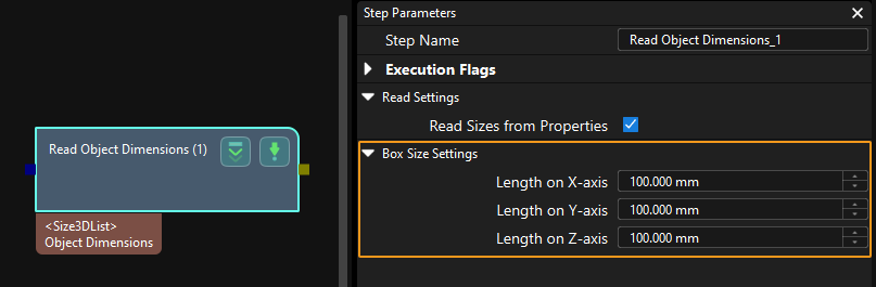
Calling Sequence
This command should be called BEFORE Command 101.
For details, see “Calling Sequence of Standard Interface Commands”.
Command Format
501, Mech-Vision project ID, length, width, height
Mech-Vision project ID
You can check the ID of a Mech-Vision project in the “Project List” panel. The number before the name of a project is its ID.
Length, width, height
The object dimensions, in mm, to be input to the Mech-Vision project. These values are read by the “Read Object Dimensions” Step and set for the parameters Length on X-axis, Length on Y-axis and Length on Z-axis.
Returned Data Format
501, status code
Status code
Status code 1108 is returned for a successful command execution. For a failed command execution, the specific error code is returned. For details, refer to Status Codes and Troubleshooting.
Examples
-
The robot sends the following command to the vision system to input the object dimensions (100 x 200 x 300 mm) to the Mech-Vision project with an ID of 1.
501, 1, 100, 200, 300 -
The vision system returns the following result. “1108” indicates that the object dimensions are successfully input to the “Read Object Dimensions” Step.
501, 1108
Command 601: Get Message from Notify Step
Description
When the Mech-Vision project or Mech-Viz project is executing the “Notify” Step, the vision system returns the message defined in the “Notify” Step.
Before sending this command, complete the following settings.
-
For a “Notify” Step in the Mech-Vision project:
-
Connect the “Notify” Step to the right side of another Step. The “Procedure Out” Step is taken as an example in the image below.
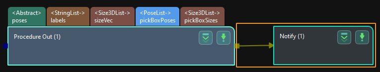
-
Select Trigger Control Flow Given Output in the parameter panel of the “Procedure Out” Step.
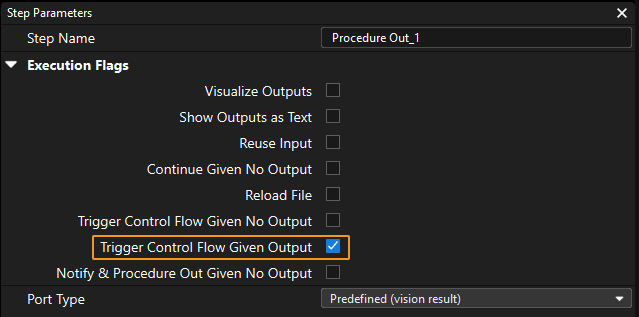
-
In the parameter panel of the “Notify” Step, enter Standard Interface Notify (a required value) for the Service Name. Enter a positive integer for Message, for example, 1001.
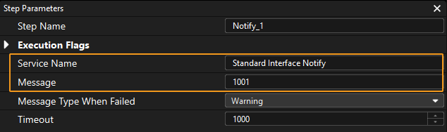
-
-
For a “Notify” Step in the Mech-Viz project:
-
Connect the “Notify” Step to a proper Step in the workflow.
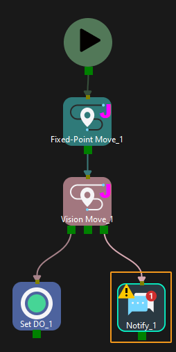
-
In the parameter panel of the “Notify” Step, select Standard Interface. Enter a positive integer for Message, for example, 1000.
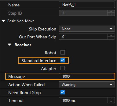
-
Calling Sequence
This command should be called immediately AFTER Command 101 or Command 201.
For details, see “Calling Sequence of Standard Interface Commands”.
Command 701: Calibration
Description
This command is used for Hand-eye calibration. It should be used together with the tool Camera Calibration (Standard) on the toolbar of Mech-Vision. In calibration, the robot first moves to the start point and sends the start point to the vision system using this command. Then, the vision system returns the position of the next calibration point; and the robot moves to this point and sends this command to require the position of the calibration point after this one. The robot and the vision system repeat the interaction until calibration is finished.
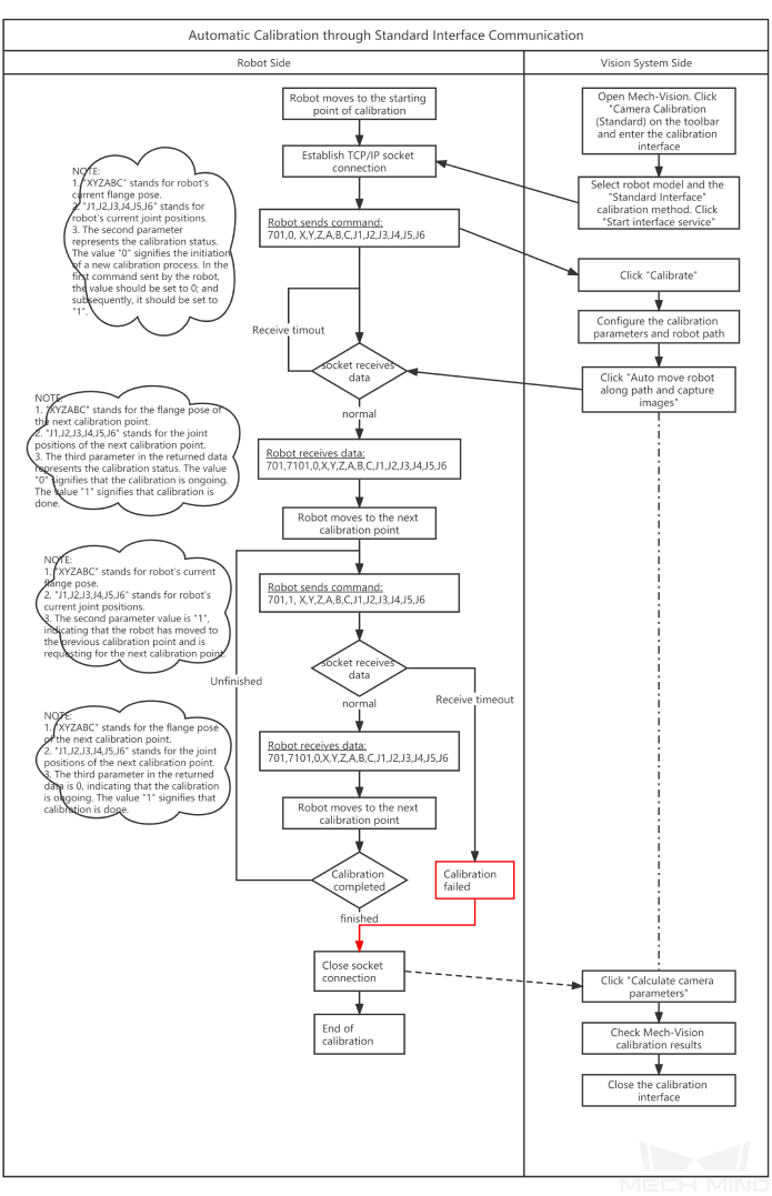
Command Format
701, calibration status, flange pose, joint positions
Calibration status
-
0: Notifies Mech-Vision to initiate the calibration.
-
1: The robot has reached the previous calibration point.
-
2: The robot failed to reach the previous calibration point.
Flange pose
The current flange pose of the robot.
Joint positions
Current joint positions of the robot.
Returned Data Format
701, status code, calibration status, flange pose of next calibration point, joint positions of next calibration point
Status code
Status code 7101 is returned for a successful command execution. For a failed command execution, the specific error code is returned. For details, refer to Status Codes and Troubleshooting.
Calibration status
-
0: In the process of calibration.
-
1: Calibration is finished.
Flange pose of next calibration point
The flange pose of the next calibration point that the robot is supposed to move to.
Joint positions of next calibration point
The joint positions of the next calibration point that the robot is supposed to move to.
Examples
-
The robot sends the following command to the vision system. “0” is to instruct Mech-Vision to start calibration, and the remaining data in the command represents the pose of the start point of calibration.
701, 0, 1371.62147, 25.6, 1334.3529, 148.58471, -179.24347, 88.75702, 88.86102, -7.11107, -28.82309, -0.44014, -67.6509, 31.4764The vision system returns the following result to the robot. “0” indicates that the calibration is in progress, and the remaining data in the command represents the pose of the next calibration point.
701, 7101, 0, 1271.6969, -74.3374, 1334.34094, -3128.422, 179.2412, -91.11236, 93.28109, -12.0273, -32.8811, -0.37183, -68.41364, 27.02411 -
The robot sends the following command to the vision system. “1” indicates that the robot has successfully reached the start point of calibration, and the remaining data in the command represents the robot’s current pose, i.e., the pose of the next calibration point in the command returned by the vision system previously.
701, 1, 1271.6969, -74.3374, 1334.34094, -3128422, 1792412, -91.11236, 93.28109, -12.0273, -32.8811, -0.37183, -68.41364, 27.02411The vision system returns the following result to the robot. “0” indicates that the calibration is in progress, and the remaining data in the command represents the pose of the next calibration point.
701, 7101, 0, 1471.62226, -74.40452, 1334.34235, 148.56924, -179.24432, 88.74148, 92.8367, -2.14999, -24.25433, -0.39222, -67.23261, 27.485225 -
Repeat the steps above to obtain following calibration points.
-
The vision system returns the following result. “1” indicates that calibration is finished. Now, the calibration process is done.
701, 7101, 1, 1371.62147, 25.6, 1334.3529, 148.58471, -179.24347, 88.75702, 88.86102, -7.11107, -28.82309, -0.44014, -67.6509, 31.4764
Command 901: Get Software Status
Returned Data Format
901, status code
Status code
Status code 1101 is returned for a successful command execution. For a failed command execution, the specific error code is returned. For details, refer to Status Codes and Troubleshooting.