ABB Standard Interface Functions
When programming the ABB robot, please pay attention to the following:
-
Multiple parameters in a function should be separated by commas.
-
Variable-type parameters should use local variables, which take effect only in the program.
-
Input or Output parameters can be customized for functions.
-
Arguments in the program: the input arguments can be constants, global variables or local variables, and the output arguments can be global variables or local variables.
|
The ABB Standard Interface provides the following functions.
Initialize Communication
This function sets the host IP address, port number, and wait time for TCP/IP communication. To establish the TCP/IP communication between the robot and the vision system, call MM_Open_Socket after this function.
Establish TCP/IP Communication
This function establishes the TCP/IP communication between the robot and the vision system. This function should be called after MM_Init_Socket.
Start Mech-Vision Project
This function is used for applications that use Mech-Vision but not Mech-Viz. This function starts the Mech-Vision project that executes image capturing and performs vision recognition.
Input Parameters
Job
Mech-Vision project ID, which can be viewed before the project name in the Project List panel in Mech-Vision.
Pos_Num_Need
The expected number of vision points for Mech-Vision to send. The vision point contains the vision pose, corresponding point cloud, label, scaling, etc.
-
0: Receive all vision points in the recognition result from Mech-Vision. -
Integer greater than 0: Receive the specified number of vision points in the recognition result from Mech-Vision.-
If the total number of vision points is less than the parameter value, all vision points in the recognition result will be received.
-
If the total number of vision points is greater than or equal to the parameter value, the specified number of vision points will be received.
-
|
SendPos_Type
The type of the robot pose to be sent to Mech-Vision. Value range: 0 to 3.
-
0: No robot poses need to be sent to the vision system. If the camera is mounted in the Eye To Hand mode, the image capturing process is independent of the robot pose, and therefore the robot pose is not needed. -
1: The robot pose in the current joint positions together with the current flange pose will be sent to the vision system. It is recommended to set this value when the camera is mounted in the Eye In Hand mode. When this parameter is set to this value, the “Path Planning” Step in the Mech-Vision project will use the joint positions sent by the robot. If the flange pose data are all 0, the vision system ignores the flange pose data. -
2: The robot pose in the current flange pose will be sent to the vision system. It is recommended to set this value when the camera is mounted in the Eye In Hand mode or in other scenarios where only the flange pose data is available (such as truss robots). -
3: The robot pose in the joint positions defined by the user will be sent to the vision system. It is recommended to set this value when the camera is mounted in the Eye To Hand mode. When this parameter is set to this value, the “Path Planning” Step in the Mech-Vision project will use the joint positions sent by the robot as the initial pose.
MM_J
User-defined joint positions. When the value of SendPos_Type is set to 3, this set of joint positions will be used as the first waypoint in the path planned by the “Path Planning” Step in the Mech-Vision project. If the value of SendPos_Type is set to values other than 3, the joint positions set here will not take effect, but it has to be set.
Get Vision Target(s)
This function should be used after executing the “Start Mech-Vision Project” function. It obtains the vision result, which contains the robot pose (in TCP format) and label, from the corresponding Mech-Vision project.
Mech-Center will automatically convert the vision point information into the corresponding robot TCP. The process includes the following steps:
-
Rotate the poses around their X axes by 180 degrees.
-
Determine whether the definition of the reference frame used by the robot model involves robot base height, and add a vertical offset accordingly.
| By default, this function can only fetch at most 20 TCPs at a time. To obtain more than 20 TCPs, call this function multiple times to obtain all TCPs. |
Input Parameters
Job
Mech-Vision project ID, which can be viewed before the project name in the Project List panel in Mech-Vision.
Output Parameters
Pos_Num
The number of received TCPs.
-
If the required number of TCPs is greater than or equal to the number of vision points recognized by Mech-Vision, the number of recognized vision points will be sent.
-
If the required number of TCPs is less than the number of the recognized vision points, the required number of vision points will be sent.
Value range: 0–20
Variable type: num
MM_Status
If there is no error, status code 1100 will be returned. Otherwise, the corresponding error code will be returned.
When this function is called, the vision system waits for the result from Mech-Vision and then sends it to the robot. The default wait time is 10 seconds. If a timeout occurs, a timeout error code will be returned to the robot.
Variable type: num
Start Mech-Viz Project
This function is for applications that use both Mech-Vision and Mech-Viz. This function runs the Mech-Viz project (which triggers the corresponding Mech-Vision project to run), and Mech-Viz will plan a robot motion path based on the vision result received from Mech-Vision.
Please right-click the Mech-Viz project to be started in Resources panel and select Autoload Project in the context menu.
There are some example projects of typical applications stored in Mech-Center/tool/viz_project in the installation directory of Mech-Vision & Mech-Viz. You can modify the example projects according to actual requirements for real applications.
Input Parameters
SendPos_Type
Robot pose type. Value range: 0 to 2.
0: No robot poses need to be sent to Mech-Viz. The simulated robot in Mech-Viz will start from joint positions [0,0,0,0,0,0] and move to the first waypoint.
1: The current joint positions and flange pose of the real robot need to be sent to Mech-Viz. The simulated robot in Mech-Viz will start from the current joint positions of the real robot and move to the first waypoint.
2:The predefined joint positions of the robot need to be sent to Mech-Viz. The simulated robot in Mech-Viz will start from the predefined joint positions and move to the first waypoint.
| When the scene contains object models that obstruct the robot to move from [0, 0, 0, 0, 0, 0] to the first waypoint, this parameter must be set to 1. |
MM_J
User-defined joint positions. User-defined joint positions. When the value of SendPos_Type is set to 2, this set of joint positions will be used as the first waypoint in the path planned by Mech-Viz. If the value of SendPos_Type is set to values other than 2, the joint positions set here will not take effect, but it has to be set.
Get Planned Path from Mech-Viz
This function obtains the planned path from Mech-Viz. It should be called after “Start Mech-Viz Project”. After the planned path is obtained, the pose data can only be accessed by calling Transfer the Obtained Robot TCP data or Transfer the Obtained Joint Positions.
By default, this function can only fetch at most 20 waypoints at a time. Therefore, it may need to be repeatedly executed until all the waypoints are obtained.
| If the waypoint of a move-type Step should not be sent to the robot, please clear the “Send Waypoint” option in the parameters of this Step. |
Input Parameters
Jps_Pos
This parameter specifies the type of waypoint pose returned by Mech-Viz.
-
1: The waypoint poses are returned in the form of joint positions (JPs). Call Transfer the Obtained Joint Positions to access the JPs data. -
2: The waypoint poses are returned in the form of tool center point (TCP). Call Transfer the Obtained Robot TCP data to access the TCP data.
Output Parameters
Pos_Num
Number of waypoints. Variable for storing the number of received waypoints which contains the corresponding pose, label, velocity.
If the planned path contains more than 20 waypoints, please repeat executing this function.
Value range: 0 to 20
VisPos_Num
The position of the waypoint in the “Vision Move” Step in the entire planned path. The “Vision Move” waypoint is the one where the robot performs the picking.
For example, if the path is composed of Steps Fixed-Point Move_1, Fixed-Point Move_2, Vision Move sequentially, the position of Vision Move is 3.
If the path does not contain any Vision Move waypoint, the returned value is 0.
MM_Status
Status code.
If there is no error, status code 2100 will be returned. Otherwise, the corresponding error code will be returned.
| When this function is called, the vision system waits for the result from Mech-Viz and then send it to the robot. The default wait time is 10 seconds. If a timeout occurs, a timeout error code will be returned to the robot. |
Example
MM_Get_VizData 2,Pos_Num,Vis_Index,StatusCode;This example obtains the planned path from Mech-Viz in the form of TCPs. The number of waypoints received is stored in the variable Pos_Num, the position of the Vision Move waypoint is stored in the variable Vis_Index, and the received status code is stored in the variable StatusCode.
Transfer the Obtained Robot TCP data
This function transfer the TCP pose data in the vision point (returned by Mech-Vision) or waypoint (returned by Mech-Vision or Mech-Viz) to the specified variable.
Transfer the Obtained Joint Positions
This function transfers the joint positions in the waypoint returned by Mech-Vision or Mech-Viz to the specified Position Registers.
Input Parameters
Index: Specify the index of the waypoint whose joint positions that will be transferred.
Switch Mech-Vision Recipe
This function specifies the parameter recipe to be used in the Mech-Vision project.
In Mech-Vision, you can change the values of Step parameters by switching the parameter recipe in use.
The parameters that can be altered by switching parameter recipes usually include the point cloud matching model, image matching template, ROI, and confidence threshold.
| This function must be called BEFORE “Start Mech-Vision Project”. |
Input Parameters
Job
Mech-Vision project ID, which can be viewed before the project name in the Project List panel in Mech-Vision.
Model_Number
Parameter recipe number.
The ID of the parameter recipe in the Mech-Vision project. The ID is a positive integer. Click to edit the parameter recipe. Value range: 1 to 99.
Select Mech-Viz Branch
This function selects along which branch the Mech-Viz project should proceed. Such branching is achieved by adding the “Branch by Msg” Step(s) to the Mech-Viz project.
“Start Mech-Viz Project” must be executed BEFORE this function.
When the next Step to execute is a “Branch by Msg” Step, the Mech-Viz project will wait for this function to specify the exit port to take.
Input Parameters
Branch_Num
Step ID of the “Branch by Msg” Step.
Exit_Num
Exit port number in integers.
| This parameter value should be 1 greater than the exit port number displayed in the Step. For example, if the specified exit port is the second exit port of the Step from left to right, the exit port number is 2. |
Set Move Index
This function sets the value of the Current Index parameter of the specified Mech-Viz Step. Steps that have this parameter include “Move by List”, “Move by Grid”, “Custom Pallet Pattern”, and “Predefined Pallet Pattern”.
“Start Mech-Viz Project” must be executed BEFORE this function.
Input Parameters
Skill_Num
Step ID.
The ID of the Step whose Current Index value needs to be set.
The value of this parameter should be a positive integer. The Step ID is displayed in the Step Parameters panel.
Index_Num
The Current Index value that should be set the next time this Step is executed.
When this function is sent, the current index value in Mech-Viz will become the parameter value minus 1.
When the Mech-Viz project runs to the Step specified by this function, the Current Index value in Mech-Viz will be increased by 1 to become the parameter’s value.
Get Software Status
This function obtains the execution status of Mech-Vision, Mech-Viz, and Mech-Center.
Currently, this function is capable of checking whether Mech-Vision is ready to run projects.
Input Object Dimensions to Mech-Vision
This function dynamically inputs object dimensions into the Mech-Vision project. Please check the actual object dimensions before running the Mech-Vision project.
The Mech-Vision project should contain the “Read Object Dimensions” Step, and the Read Sizes from Properties checkbox of this Step should be selected.
Input Parameters
Job
Mech-Vision project ID, which can be viewed before the project name in the Project List panel in Mech-Vision.
Length, Width, Height
The object dimensions (length, width, height) to be input to the Mech-Vision project. The dimensions will be read into the “Read Object Dimensions” Step.
The unit is millimeter.
Get Gripper DO List
This function gets the DO signal list planned in Mech-Vision or Mech-Viz. The robot apply the obtained DO list signals to the tool by calling MM_Set_DoList.
Set Gripper DO List
This function sets the DO list sent by Mech-Vision or Mech-Viz to GO signals. It supports 4 groups of 16-bit GO signals in maximum. If you need to set multiple groups of GO signals, please run this function for several times.
| MM_Get_DoList must be called BEFORE this function. |
Calibration
This function is used for hand-eye calibration (camera extrinsic parameter calibration).
This function synchronizes the calibration status with Mech-Vision and obtains the next calibration point that the robot needs to reach from Mech-Vision.
This function must be executed multiple times to complete the calibration.
Input Parameters
| Parameter | Description |
|---|---|
Move_Type |
The motion type of the robot. 1: MoveL. 2: MoveJ. |
Pos_Jps |
Pose as flange pose or joint positions. 1: TCP. 2: Joint positions. |
Wait_time |
The time the robot waits to avoid shaking after it moves to the calibration point; the default value is 2 (s). |
Ext |
Data of the external 7th axis in mm, optional. |
Example
-
Example 1:
MM_Calib 2,1,2;This example moves the robot in MoveJ type, receives pose data in the form of TCP, and sets the wait time to 2 seconds to avoid the robot from shaking after it moves to the calibration point. In addition, this robot does not have an external axis installed.
-
Example 2:
MM_Calib 2,1,2\EXT:=Axis7;This example moves the robot in MoveJ type, receives pose data in the form of TCP, and sets the wait time to 2 seconds to avoid the robot from shaking after it moves to the calibration point. Moreover, the 7th axis value of this robot is Axis7.
Get Custom Output Data from Mech-Vision
This function obtains the custom output data from the corresponding Mech-Vision project. “Custom output data” refers to the data output by ports other than poses and labels of the “Procedure Out” Step. The output ports can be customized if the “Port Type” parameter of the Step is set to “Custom”.
Call this function once and you can obtain and store all data to the robot.
Input Parameters
job
Variable type: num. Mech-Vision project ID, which can be viewed before the project name in the Project List panel in Mech-Vision.
Output Parameters
Pos_Num
Variable type: num. Variable for storing the number of received vision points.
MM_Status
Variable type: num. Variable for storing the status code.
Example
MM_Get_DyData 2,Pos_Num,StatusCode;This example obtains the vision result that includes custom port outputs from Mech-Vision project No. 2. The number of vision points received is stored in Pose_Num, and the status code is stored in Status. The obtained poses and corresponding labels are stored in the global variable MMvis2_Pose, and the corresponding custom port outputs are stored in the global variable UserData.
Save Custom Output Data to Specified Variables
This function stores the data in a vision point returned by Get Custom Output Data from Mech-Vision in the specified variables.
Input Parameters
Serial
Variable type: num. Specify the index of the vision point in which the custom data you want to store. The index is defined by the sequence that Mech-Vision sends the data.
Output Parameters
MM_P
Variable in the robtarget data type. for storing the pose in the specified vision point.
MM_Label
Variable type: num. Variable for storing the label in the specified vision point (If there is not a label port in Mech-Vision, 0 will be filled in automatically).
MM_UserData
Variable type: num. Global array variable for storing the custom port outputs in the specified vision point. You can read the array directly without the need to pass the parameter.
Get Vision Move Data or Custom Output Data
This function obtains Vision Move data from the Mech-Vision project, or the Vision Move data or custom output data from the Mech-Viz project. Call MM_Get_PlanPose or MM_Get_PlanJps to assign the received data to variables.
Input Parameters
Resource
Variable type: num. This parameter specifies the source of the Vision Move data.
-
0: Get Vision Move data from Mech-Viz.
-
Positive integer: Get Vision Move data from Mech-Vision. The positive integer is the Mech-Vision project ID.
Jps_Pos
Variable type: num. This parameter specifies the expected format of the returned data.
-
When the value of Resource is 0, the valid value range of Jps_Pos is 1 to 4. Details are provided below.
Value of Jps_Pos Format of returned data (Explained below) 1
Pose (joint positions), motion type, tool ID, velocity, element 1 in custom output data, … element N in custom output data
2
Pose (TCP), motion type, tool ID, velocity, element 1 in custom output data, … element N in custom output data
3
Pose (joint positions), motion type, tool ID, velocity, Mech-Viz Vision Move data, element 1 in custom output data, … element N in custom output data
4
Pose (TCP), motion type, tool ID, velocity, Mech-Viz Vision Move data, element 1 in custom output data, … element N in custom output data
-
When the value of Resource is a positive integer, the valid value range of Jps_Pos is 1 to 2. Details are provided below.
Value of Jps_Pos Format of returned data (Explained below) 1
Pose (joint positions), motion type, tool ID, velocity, Mech-Vision Vision Move data
2
Pose (TCP), motion type, tool ID, velocity, Mech-Vision Vision Move data
Pose
The pose of the waypoint can be in the form of joint positions (in degree) or TCP, which is composed of Cartesian coordinates (XYZ in mm) and Euler angles (ABC in degree).
Motion type
-
1: joint motion (MOVEJ)
-
2: linear motion (MOVEL)
Tool ID
The ID of the tool to be used at this waypoint. The value “-1” means that no tool will be used at this waypoint.
Velocity
The velocity at this waypoint.
Vision Move data
Data output by the “Vision Move” Step in Mech-Vision or Mech-Viz, including labels of picked workobjects, number of picked workobjects, number of workobjects to be picked this time, edge/corner ID of vacuum gripper, TCP offset, orientation of workobject group, orientation of workobject, dimensions of workobject group.
Element in custom output data
“Custom output data” refers to the data output by ports other than poses and labels of the “Procedure Out” Step in the Mech-Vision project. The output ports can be customized if the “Port Type” parameter of the Step is set to “Custom”.
The data output by custom ports are arranged in alphabetical order of the custom port names.
Output Parameters
Pos_Num
Variable type: num. Variable for storing the number of received waypoints.
VisPos_Num
Variable type: num. Variable for storing the position of the first Vision Move waypoint in the path. For example, if the path is composed of Steps Fixed-Point Move_1, Fixed-Point Move_2, Vision Move, and Fixed-Point Move_3 sequentially, the position of Vision Move is 3. If the path does not contain “Vision Move”, the value of this parameter is 0.
MM_Status
Variable type: num. Variable for storing the status code.
Example
MM_GET_PLANDATA 0,4,PosNum,Vis_Index,StatusCode;This example obtains the planned path that includes depalletizing planning data and custom port outputs from Mech-Viz, and the poses obtained are in the form of TCPs. The number of waypoints received is stored in PosNum, the position of the Vision Move waypoint is stored in Vis_Index, and the status code is stored in StatusCode.
Save Waypoint to Specified Variables
This function stores the values obtained by calling MM_GET_PLANDATA in variables. The obtained values are assigned to different variables based on the value of the Jps_Pos parameter in the MM_GET_PLANDATA function.
Function
MM_Get_PlanPose Serial,Jps_Pos,MM_P,MM_MoveType,MM_ToolNum,MM_Speed; (when the value of Jps_Pos is 2 or 4)
MM_Get_PlanJps Serial,Jps_Pos,MM_J,MM_MoveType,MM_ToolNum,MM_Speed; ( when the value of Jps_Pos is 1 or 3)
Input Parameters
Serial
Variable type: num. Specify the index of the waypoint to be stored. The index of the waypoint is determined by the order in which Mech-Viz sends data.
Jps_Pos
Variable type: num. The parameter value should be the same as that of Jps_Pos in MM_GET_PLANDATA.
Output Parameters
MM_P
Variable type: robtarget. Variable for storing the TCP in the specified waypoint.
MM_J
Variable type: Jointtarget. Variable for storing the joint positions in the specified waypoint.
MM_MoveType
Variable type: num. Used for storing the motion type at the specified waypoint.
MM_ToolNum
Variable type: num. Used to store the tool ID in the specified waypoint.
MM_Speed
Variable type: num. Variable for storing the velocity in the specified waypoint.
MM_UserData
Global array variable that can be read directly without the need for parameter passing. Used for storing the custom port outputs in the specified waypoint.
MM_Plan_Results
Global array variable that can be read directly without the need for parameter passing. Used for storing the Vision Move data corresponding to the specified waypoint. The size of the array is 21.
Content of the MM_Plan_Results array is explained in the table below.
| Value | Description | Variable |
|---|---|---|
Labels of picked workobjects |
Consists of 10 integers. By default, its value is ten 0s. |
MM_Plan_Results[1] - MM_Plan_Results[10] |
Number of picked workobjects |
The total number of workobjects that have been picked. |
MM_Plan_Results[11] |
The number of workobjects to be picked this time. |
The number of workobjects to be picked this time. |
MM_Plan_Results[12] |
Edge/corner ID of vacuum gripper |
The ID of the edge/corner used to pick workobjects this time. |
MM_Plan_Results[13] |
TCP offset |
The XYZ offset between the center of the workobject group and the tool pose center |
MM_Plan_Results[14] - MM_Plan_Results[16] |
Orientation of workobject group |
The relative position between the workobject group and the length of the vacuum gripper. The value is 0 or 1, where 0 stands for parallel and 1 for vertical. |
MM_Plan_Results[17] |
Orientation of workobject |
The relative position between the length of a workobject and that of the vacuum gripper. The value is 0 or 1, where 0 stands for parallel and 1 for vertical. |
MM_Plan_Results[18] |
Dimensions of the workobject group |
The length, width and height of the workobject group to be picked this time. |
MM_Plan_Results[19] - MM_Plan_Results[21] |
Example
-
Example 1:
MM_Get_PlanPose 2,4,P10,MoveType,ToolNum,Speed;This example stores the TCP in the second waypoint received from Mech-Viz to P10, the corresponding motion type to MoveType, the corresponding tool ID to ToolNum, the corresponding velocity to Speed. If the waypoint is not a Vision Move waypoint, there is no further information; if it is a Vision Move waypoint, the corresponding Vision Move data will be stored to MM_Plan_Results, and the corresponding custom port outputs will be stored to MM_UserData.
-
Example 2:
MM_Get_PlanJps 1,3,jpose1,MoveType,ToolNum,Speed;This example stores the joint positions in the first waypoint received from Mech-Viz to jpose1, the corresponding motion type to MoveType, the corresponding tool ID to ToolNum, the corresponding velocity to Speed. If the waypoint is not a Vision Move waypoint, there is no further information; if it is a Vision Move waypoint, the corresponding Vision Move data will be stored to MM_Plan_Results, and the corresponding custom port outputs will be stored to MM_UserData.
Get Result of Step “Path Planning” in Mech-Vision
This function obtains the collision-free path planned by the “Path Planning” Step from the corresponding Mech-Vision project.
The Port Type parameter of the “Procedure Out” Step in the Mech-Vision project must be set to “Predefined (robot path)”.
Input Parameters
Job
Variable type: num. Mech-Vision project ID, which can be viewed before the project name in the Project List panel in Mech-Vision.
Jps_Pos
Variable type: num. The pose type of waypoints returned by the “Path Planning” Step.
-
1: Waypoints in joint positions will be returned. -
2: Waypoints in TCPs will be returned.
Output Parameters
Pos_Num
Variable type: num. Variable for storing the number of received waypoints.
VisPos_Num
Variable type: num. The position of the “Vision Move” waypoint in the entire planned path in the Path Planning tool. For example, if the path is composed of Steps Fixed-Point Move_1, Fixed-Point Move_2, Vision Move, and Fixed-Point Move_3 sequentially, the position of Vision Move is 3. If the path does not contain “Vision Move”, the value of this parameter is 0.
MM_Status
Variable type: num. Variable for storing the status code.
Example
MM_Get_VisPath 2,2,PosNum,Vis_Index,StatusCode;This example obtains the planned path from Mech-Vision project No. 2 in the form of TCPs. The number of waypoints received is stored in the variable PosNum, the position of the Vision Move waypoint is stored in the variable Vis_Index, and the status code is stored in the variable StatusCode.
Trigger Mech-Vision Project and Get Results
This function triggers the following operations in sequence: First, set the parameter recipe to be used by the Mech-Vision project (which is skipped if the project doesn’t have a parameter recipe). Second, trigger the Mech-Vision project to run. Third, obtain vision results (i.e., vision points, waypoints, or custom output data) from the vision system. This function equals the combination of Switch Mech-Vision Recipe, Start Mech-Vision Project, Get Vision Target(s), Get Result of Step “Path Planning” in Mech-Vision and Get Custom Output Data from Mech-Vision.
| At most 20 poses can be obtained by calling this function. To obtain more than 20 poses, call Switch Mech-Vision Recipe, Start Mech-Vision Project, Get Vision Target(s), Get Result of Step “Path Planning” in Mech-Vision or Get Custom Output Data from Mech-Vision instead. |
Input Parameters
Job
Variable type: num. Mech-Vision project ID, which can be viewed before the project name in the Project List panel in Mech-Vision.
Model_Number
Variable type: num. The ID of the parameter recipe in the Mech-Vision project. The valid range is 0 to 99. 0 indicates that the Mech-Vision project does not use a parameter recipe.
Recv_Data_Type
Variable type: num. This parameter specifies the data type returned by the vision system. The valid range is 1 to 4.
-
1: The vision system returns vision points (without custom port output). Users need to call MM_Get_Pose later to store the pose of the vision point to the specified variable. -
2: The vision system returns vision points (together with custom port output). Users need to call MM_Get_DyPose later to store the pose of the vision point to the specified variable. -
3: The vision system returns waypoints in the form of JPs. Users need to call MM_Get_Jps later to store the pose of the waypoint to the specified variable. -
4: The vision system returns waypoints in the form of TCP. Users need to call MM_Get_Pose later to store the pose of the waypoint to the specified variable.
Output Parameters
MM_Status
Variable type: num. Variable for storing the status code.
Pos_Num (Optional)
Variable type: num. Used for storing the number of received vision points or waypoints.
VisPos_Num (Optional)
Variable type: num. This parameter is meaningful only when the value of Recv_Data_Type is 3 or 4. This parameter stores the position of the first “Vision Move” waypoint in the entire planned path. For example, if the path is composed of Steps Fixed-Point Move_1, Fixed-Point Move_2, Vision Move, and Fixed-Point Move_3 sequentially, the position of Vision Move is 3. If the path does not contain “Vision Move”, the value of this parameter is 0.
Example
MM_Lite_Vis 1,2,1,MMStatus,\Pos_Num:=PoseNum;This example obtains vision points output by Project 1 of Mech-Vision. Before triggering the Mech-Vision project to run, it sets the parameter recipe with an ID of 2 to the project. The number of obtained vision points is stored in the variable PoseNum, and the status code of command execution is stored in the variable MMStatus.
Trigger Mech-Viz Project and Get Planned Path
This function triggers the following operations in sequence: First, start the Mech-Viz project. Second, set the Exit port for the Branch by Msg Step(which is skipped if the project doesn’t have a parameter recipe). Last, return the path planned by the Mech-Viz project. This function equals the combination of Start Mech-Viz Project, Select Mech-Viz Branch and Get Planned Path from Mech-Viz.
| At most 20 poses can be obtained by calling this function. To obtain more than 20 poses, call Start Mech-Viz Project, Select Mech-Viz Branch or Get Planned Path from Mech-Viz instead. |
Input Parameters
Branch_Num
Variable type: num. This parameter specifies the “Branch by Msg” Step by its ID. The valid value range is 0 to 99. 0 indicates that the Mech-Viz project does not have a Branch by Msg Step.
Export_Num
Variable type: num. This parameter specifies the exit port of the “Branch by Msg” Step. The value is a positive integer. When the parameter value is set to “N”, the project exits from the port with an ID of “N-1” of the “Branch by Msg” Step.
Recv_Data_Type
Variable type: num. This parameter specifies the data type returned by the vision system. The valid range is 1 to 2.
-
1: The vision system returns waypoints in the form of JPs. Users need to call MM_Get_Jps later to store the pose of the waypoint to the specified variable. -
2: The vision system returns waypoints in the form of TCP. Users need to call MM_Get_Pose later to store the pose of the waypoint to the specified variable.
Output Parameters
MM_Status
Variable type: num. Variable for storing the status code.
Pos_Num (Optional)
Variable type: num. Variable for storing the number of received waypoints.
VisPos_Num (Optional)
Variable type: num. This parameter stores the position of the first “Vision Move” waypoint in the entire planned path. For example, if the path is composed of Steps Fixed-Point Move_1, Fixed-Point Move_2, Vision Move, and Fixed-Point Move_3 sequentially, the position of Vision Move is 3. If the path does not contain “Vision Move”, the value of this parameter is 0.
Example
MM_Lite_Viz 1,2,1,MMStatus,\Pos_Num:=PoseNum;This example obtains waypoints output by the Mech-Viz project. The Mech-Viz project takes port 1 as the exit of the Branch by Msg Step. The number of obtained waypoints is stored in the variable PoseNum, and the status code of command execution is stored in the variable MMStatus.
Get Message from Notify Step
Read Mech-Viz Step Parameter
This function reads the parameter value of a specific Step in the Mech-Viz project.
Input Parameters
Get_Id
This parameter corresponds to the Config ID field defined in the property_config file.
|
From the toolbar of Mech-Vision, go to . Click Property Configuration to open the property_config file. 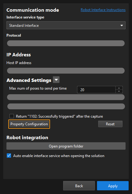
|
Before calling this function, users should define a Config ID and its corresponding Step ID and parameter key name in the following format in the property_config file.
read, Config ID, Step ID, parameter key name
read |
Indicates that this line is used to read the parameter value of a Step. |
Config ID |
Specifies a unique ID, which in a positive integer. One Config ID corresponds to only one parameter value of a Step. To read multiple parameter values, you should set different Config IDs. |
Step ID |
The Step ID of the Step whose parameter is to be read. |
Parameter key name |
Specifies the key name of the parameter whose value the robot requires to read. |
|
|
The property_config file can have multiple read commands. The Config ID in these commands must be different. |
Output Parameters
MM_Status
An integer variable used to store the status code.
Viz_Prop
An integer variable used to store the returned parameter value of the specified Step.
Example
In the line below, “5” is the Config ID; “3” is the Step ID; and “xCount” is the parameter key name. Add this line to the property_config file. Add this line to the property_config file.
read, 5, 3, xCountWhen the robot calls the function below, it receives the value of the parameter whose key name is “xCount”.
MM_Get_Property 5,MM_Status,Viz_Prop;This example stores the value of the parameter whose key name is “xCount” of Step 3 in the Mech-Viz project to the Viz_Prop variable, and stores the received status code to the “MM_Status” variable.
Set Mech-Viz Step Parameter
This function sets the parameter value of a specific Step in the Mech-Viz project.
Input Parameters
Set_Id
This parameter corresponds to the Config ID field defined in the property_config file.
|
From the toolbar of Mech-Vision, go to . Click Property Configuration to open the property_config file.
|
Before sending this command, users should define a Config ID and its corresponding Step ID, parameter key name and parameter value in the following format in the property_config file.
write, Config ID, Step ID, parameter key name, parameter value
write |
Indicates that this line is used to set the parameter value of a Step. |
Config ID |
Specifies an ID, which is a positive integer and can be used repeatedly. |
Step ID |
Specifies the Step whose parameter value the robot requires to read. |
Parameter key name |
Specifies the key name of the parameter whose value the robot requires to set. |
Parameter value |
Specifies the value that the robot sets for the parameter. |
|
Example
In the line below, “1” is the Config ID, and “3” is the Step ID. “xOffset”, “yOffset” and “zOffset” are parameter key names; and “10”, “20” and “30” are their respective values. Add this line to the property_config file.
write, 1, 3, xOffset, 10
write, 1, 3, yOffset, 20
write, 1, 3, zOffset, 30
When the robot calls the function below, Mech-Viz sets the values of the parameters whose key names are “xOffset”, “yOffset” and “zOffset” respectively to “10”, “20” and “30”.
MM_Set_Property 1,MM_Status;This example sets the values of the parameters whose key names are “xOffset”, “yOffset” and “zOffset” respectively to “10”, “20” and “30”, and stores the received status code in the “MM_Status” variable.