EtherNet/IP–MITSUBISHI iQ-R Series PLC Functions
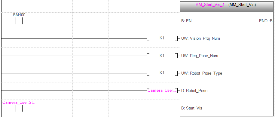
Command 101: Start Mech-Vision Project
This function starts the Mech-Vision project that executes image capturing and performs vision recognition. It applies for applications that use Mech-Vision but not Mech-Viz.
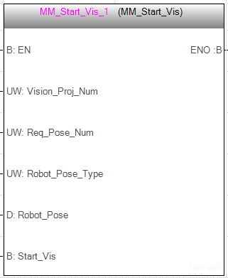
Input parameters
| Name | Description |
|---|---|
Vision_Proj_Num |
Mech-Vision Project ID |
Req_Pose_Num |
Expected number of vision points |
Robot_Pose_Type |
Robot pose type |
Robot_Pose |
The pose received from the robot |
Start_Vision |
Trigger signal |
Mech-Vision Project ID
The Project ID of the Mech-Vision project to be triggered; you can check the project ID before the project name in the Project List panel in Mech-Vision.
Expected number of vision points
The expected number of vision points for Mech-Vision to send. The vision point contains the vision pose, corresponding point cloud, label, scaling, etc.
-
0: Receive all vision points in the recognition result from Mech-Vision. -
Integer greater than 0: Receive the specified number of vision points in the recognition result from Mech-Vision.-
If the total number of vision points is less than the parameter value, all vision points in the recognition result will be received.
-
If the total number of vision points is greater than or equal to the parameter value, the specified number of vision points will be received.
-
| The function is used to obtain the vision points is Command 102. Command 102 can only fetch at most 20 vision targets at a time by default. To obtain more than 20 vision targets, please execute Command 102 repeatedly. |
Robot pose type and Robot pose
-
Robot_Pose_Type: The type of robot pose to input to Mech-Vision. The value range is 0 to 3.
-
Robot_Pose: The pose received from the robot, value depends on the value of Robot_Pose_Type. Data type: two-dimensional array [0..1, 0..5] of DInt, array[0] is joint positions and array[1] is flange pose.
The following table explains the relationship between Robot_Pose_Type and Robot_Pose.
| Robot_Pose_Type value | Robot_Pose value | Description | Applicable Scenarios |
|---|---|---|---|
0 |
0, 0, 0, 0, 0, 0 |
No need to input robot pose to Mech-Vision |
Project is in the eye-to-hand mode. If the “Path Planning” Step is used in the Mech-Vision project, the planned path starts at the Home point set in the path planning tool. |
1 |
Current joint positions and flange pose of the robot |
Robot joint positions and flange pose must be input to Mech-Vision |
Project is in the eye-in-hand mode. Applicable to most robots (excluding truss robots). |
2 |
Current flange pose of the robot |
Robot flange pose must be input to Mech-Vision |
Project is in the eye-in-hand mode. The robot has no joint positions and only flange pose (such as truss robots). |
3 |
Joint positions of the start point of the planned path |
The joint positions of the path start point must be input to Mech-Vision |
Project is in the eye-to-hand mode and the Mech-Vision project contains the “Path Planning” Step, whose start point needs to be set from the robot side. |
|
Before assigning to the Robot_Pose array, multiply the floating-point numbers that represent joint positions or the robot flange pose by 10000 to convert the data to 32-bit signed integers. |
Trigger signal
Trigger Mech-Vision project to start when a rising edge occurs.
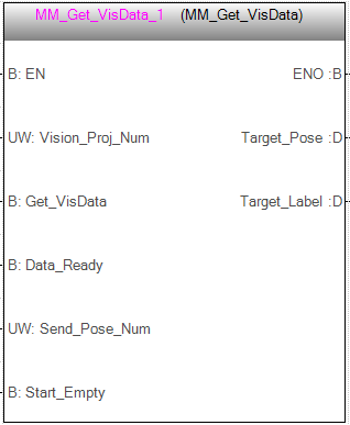
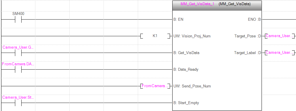
Command 102: Get Vision Target(s)
This function should be used after executing Command 101: Start Mech-Vision Project. It obtains the vision result, which contains the robot pose (in TCP format) and label, from the corresponding Mech-Vision project.
Mech-Center will automatically convert the vision point information into the corresponding robot TCP. The process includes the following steps:
-
Rotate the poses around their X axes by 180 degrees.
-
Determine whether the definition of the reference frame used by the robot model involves robot base height, and add a vertical offset accordingly.
| By default, this function can only fetch at most 20 TCPs at a time. Therefore, the function may need to be repeatedly executed until all TCPs required are obtained. |
Input parameters
| Name | Description |
|---|---|
Vision_Proj_Num |
Mech-Vision Project ID |
Get_VisData |
Obtain vision points |
Data_Ready |
Data available to read |
Send_Pose_Num |
The number of TCPs |
Start_Empty |
Clear the obtained data |
Mech-Vision Project ID
The Project ID of the Mech-Vision project to be triggered; you can check the project ID before the project name in the Project List panel in Mech-Vision.
Obtain vision points
Obtain vision points from the project when a rising edge occurs.
Data available to read
All the pose data is available to read when receiving multiple groups of robot poses.
The number of TCPs
The number of received TCPs.
Clear the obtained data
Clear the obtained data stored in Target_Pose and Target_Label. This parameter will take effect when it is set to 1.
Output parameters
| Name | Description |
|---|---|
Target_Pose |
Obtained robot TCPs |
Target_Label |
Obtained labels |
Obtained robot TCPs
Each TCP consists of the Cartesian coordinates (XYZ) and Euler angles (ABC).
Obtained labels
The integer labels corresponding to the obtained poses. If the labels in the Mech-Vision project are strings, please use the “Label Mapping” Step before the “Procedure Out” Step to map the labels to integers. If there are no labels in the project, the value of this parameter is 0.
Returned Data from the FromCamera Global Tag
FromCamera.STATUS_CODE: Status code
If there is no error, status code 1100 will be returned. Otherwise, the corresponding error code will be returned.
FromCamera.SEND_POSE_TYPE: Pose type
This parameter indicates that the target object pose in the vision point returned by Mech-Vision is converted to robot TCP by Mech-Center.
The value of this parameter is always 2, which stands for TCP.
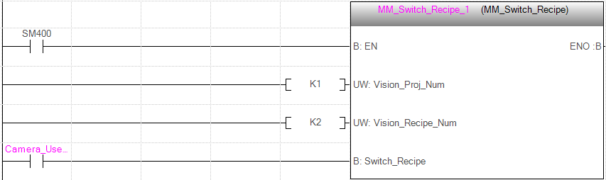
Command 103: Switch Mech-Vision Recipe
This function specifies the parameter recipe to be used in the Mech-Vision project.
In Mech-Vision, you can change the values of Step parameters by switching the parameter recipe in use.
The parameters that can be altered by switching parameter recipes usually include point cloud matching model, image matching template, ROI, and confidence threshold.
| This function must be called BEFORE Command 101: Start Mech-Vision Project. |
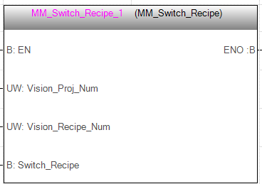
Input parameters
| Name | Description |
|---|---|
Vision_Proj_Num |
Mech-Vision Project ID |
Vision_Recipe_Num |
Mech-Vision recipe ID |
Switch_Recipe |
Trigger signal |
Mech-Vision Project ID
Mech-Vision Project ID, which can be checked and adjusted in Mech-Vision.
Mech-Vision recipe ID
The ID of the parameter recipe in the Mech-Vision project. The ID is a positive integer. Click to edit the parameter recipe.
Trigger signal
Switch the parameter recipe in the Mech-Vision project when a rising edge occurs.
Command 105: Get Result of Step “Path Planning” in Mech-Vision
After executing Command 101, execute this function to obtain the collision-free picking path planned by the “Path Planning” Step in the Mech-Vision project.
When using this function, set the Port Type parameter of the “Procedure Out” Step in the Mech-Vision project to “Predefined (robot path)”.
| Before executing this function, please set Req_Pose_Num in MM_Start_Vis to 0 to reduce the times of execution of this function. If Req_Pose_Num in is set to 1, every time this function is executed, only 1 waypoint is returned, and this function must be executed multiple times to obtain all the waypoints. |
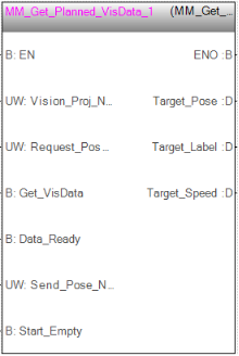
Input parameters
-
Vision_Proj_Num: Mech-Vision project ID, which is the number before the project name in the Project List panel in Mech-Vision.
-
Request_Pose_Type: Specify the type of waypoint pose returned by the “Path Planning” Step.
-
1: The waypoint poses are returned in the form of joint positions (JPs). -
2: The waypoint poses are returned in the form of tool center point (TCP).
-
-
Get_VisData: Obtains the planned path from the “Path Planning” Step in Mech-Vision at the rising edge.
-
Data_Ready: Indicates the pose data is readable when receiving multiple sets of robot pose data.
-
Send_Pose_Num: The number of poses to be sent, from 0 to 20.
-
Start_Empty: Clear the obtained data stored in Target_Pose, Target_Label, and Speed_Percentage.This variable will take effect when it is set to 1.
Output parameters
-
Target_Pose: The waypoint pose in TCP. The data type is Array[0..19, 0..5] of DInt. This array should be divided by 10000 before being used.
-
Target_Label: The label information of the object recognized by Mech-Vision. The data type is Array[0..19] of UDInt. The returned values are integers.
-
Target_Speed: The speed in percentage set in the move-type Step parameters, from 1 to 100.
Returned Data from the FromCamera Global Tag
-
FromCamera.STATUS_CODE: If there is no error, status code 1103 will be returned. Otherwise, the corresponding error code will be returned.
-
FromCamera.SEND_POSE_TYPE: The pose type of the waypoint, which is consistent with that of the Request_Pose_Type input parameter. 1 indicates JPs, while 2 indicates TCP.
-
FromCamera.VISUAL_POINT_INDEX: The position of the Vision Move Step in the entire robot motion path.
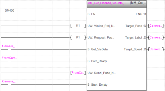
Example
When there is a rising edge on the variable Camera_User.Get_VisData, the path planned by the Mech-Vision project No.1 will be obtained in the form of joint positions. When Camera_User.Start_Empty is set to 1, data stored in Camera_User.Target_Pose, Camera_User.Target_Label, and Camera_User.Target_Speed will be cleared.
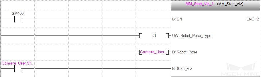
Command 201: Start Mech-Viz Project
This function is for applications that use both Mech-Vision and Mech-Viz. This function runs the Mech-Viz project (which triggers the corresponding Mech-Vision project to run), and Mech-Viz will plan a robot motion path based on the vision result received from Mech-Vision.
Please right-click the Mech-Viz project to be started in Resources panel and select Autoload Project in the context menu.
There are some example projects of typical applications stored in Mech-Center/tool/viz_project in the installation directory where Mech-Vision and Mech-Viz are installed. You can modify the example projects according to actual requirements for real applications.
Please refer to “standard_interface_viz_sample_projects” for Mech-Viz example projects used for Standard Interface.
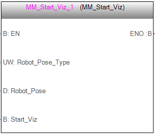
Input parameters
| Name | Description |
|---|---|
Robot_Pose_Type |
Robot pose type |
Robot_Pose |
Robot pose |
Start_Viz |
Trigger signal |
Robot pose type and Robot pose
-
Robot_Pose_Type: The type of robot pose to input to Mech-Viz. The value range is from 0 to 2.
-
Robot_Pose: The pose received from the robot, value depends on the value of Robot_Pose_Type. Data type: two-dimensional array [0..1, 0..5] of DInt, array[0] is joint positions and array[1] is flange pose.
The following table explains the relationship between Robot_Pose_Type and Robot_Pose.
| Robot_Pose_Type value | Robot_Pose value | Description | Applicable Scenarios |
|---|---|---|---|
0 |
0, 0, 0, 0, 0, 0 |
No need to input the robot pose to Mech-Viz. The simulated robot in Mech-Viz moves from the initial pose JPs = [0, 0, 0, 0, 0, 0] to the first waypoint. |
Project is in the eye-to-hand mode. This setting is not recommended. |
1 |
Current joint positions and flange pose of the robot |
Robot joint positions and flange pose must be input to Mech-Viz. The simulated robot in Mech-Viz moves from the input JPs to the first waypoint. |
This setting is recommended for projects in the eye-in-hand mode. |
2 |
Specific joint positions of the robot |
The robot joint positions of a point determined by teaching must be input to Mech-Viz. The input joint positions are used to trigger Mech-Viz to plan the next path in advance while the robot is not in the camera capture region, as shown below. The simulated robot in Mech-Viz moves from the input joint positions to the first waypoint. |
This setting is recommended for projects in the eye-to-hand mode. |
|
The reason for setting Robot_Pose_Type to 2 when the project is in the eye-to-hand mode:
In the eye-to-hand mode, the camera can perform image capturing for the next round of path planning before the robot returns to the camera capture region and picking region, shortening the cycle time. If Robot_Pose_Type is set to 1, the robot’s current pose is sent to Mech-Viz. The simulated robot will move from the input pose to the first waypoint in the planned path, while the real robot might move to another point first, and then move to the first waypoint. Therefore, the path of the real robot may contain unpredicted collisions, leading to safety hazards. In conclusion, Robot_Pose_Type should be set to 2 for projects in the eye-to-hand mode. 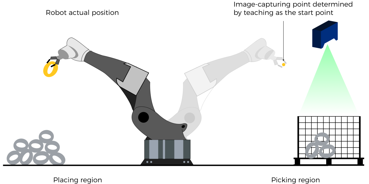
|
| Before assigning to the Robot_Pose array, multiply the floating-point numbers that represent joint positions or the robot flange pose by 10000 to convert the data to 32-bit signed integers. |
Trigger signal
Trigger Mech-Viz project to start when a rising edge occurs.
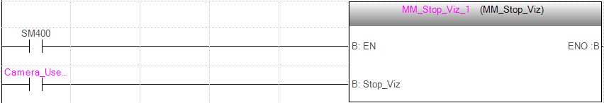
Command 202: Stop Mech-Viz Project
This function stops the execution of Mech-Viz. This function is only needed if the Mech-Viz project falls into an infinite loop or cannot be stopped normally.
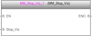
Input parameters
| Name | Description |
|---|---|
Stop_Viz |
Trigger signal |
Trigger signal
Trigger Mech-Viz project to stop when a rising edge occurs.
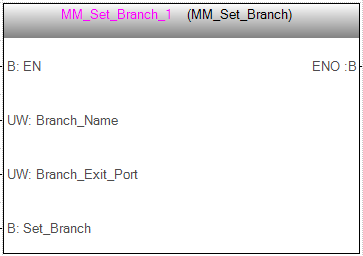
Command 203: Select Mech-Viz Branch
This function is used to select along which branch the project should proceed. Such branching is achieved by adding Branch by Msg Step(s) to the project. This function specifies which exit port such Step(s) should take.
Command 201: Start Mech-Viz Project must be executed BEFORE this function.
When the next Step is a “Branch by Msg” Step, the Mech-Viz project will wait for this function to specify the exit port to take.
Input parameters
| Name | Description |
|---|---|
Branch_Name |
Step ID of the “Branch by Msg” Step |
Branch_Exit_Port |
Exit port number |
Set_Branch |
Trigger signal |
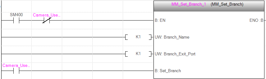
Step ID of the “Branch by Msg” Step
This parameter specifies the Branch by Msg Step in which the branch will be selected.
Step ID of the Branch by Msg Step, an integer. The Step ID is displayed in the parameters of the Step.
Exit port number
This parameter specifies the exit port of the Branch by Msg Step in the Mech-Viz project that should be taken. This parameter should be an integer.
- NOTE
-
-
This parameter value should be 1 greater than the exit port number displayed in the Mech-Viz Step. For example, to select exit port 0, set the value of this parameter to 1.
-
An exit port number is the 1-based index of the specified exit port on the Step. For example, if the specified exit port is the second exit port of the Step from left to right, the exit port number is 2.
-
Trigger signal
Specify the port which Branch by Msg Step should take.
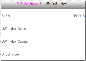
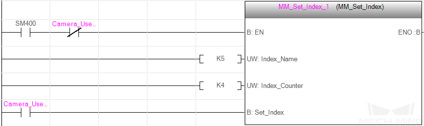
Command 204: Set Move Index
This function sets the value for the Current Index parameter of Mech-Viz Steps. Steps that have this parameter include “Move by List”, “Move by Grid”, “Custom Pallet Pattern”, and “Smart Pallet Pattern”.
Command 201: Start Mech-Viz Project must be executed BEFORE this function.
Input parameters
| Name | Description |
|---|---|
Index_Name |
Step ID |
Index_Counter |
Index value |
Set_Index |
Trigger signal |
Step ID
The Step ID of the Step whose Current Index value needs to be set.
The value of this parameter should be a positive integer. The Step ID is displayed in the parameters of the Step.
Index value
The index value that should be set the next time this Step is executed.
When this function is sent, the current index value in Mech-Viz will become the parameter value minus 1.
When the Mech-Viz project runs to the Step specified by this function, the current index value in Mech-Viz will be increased by 1 to become the parameter’s value.
Trigger signal
The trigger signal to set the index. The rising edge does the trigger.
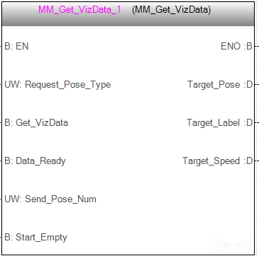
Command 205: Get Planned Path
This function obtains the planned path from Mech-Viz. It should be used after executing Command 201: Start Mech-Viz Project function to obtain the planned path.
| If any waypoint of move-type Steps should not be sent to the robot, please uncheck the “Send Waypoint” option in the parameters of this Step. |
| This function can only send at most 20 waypoints at a time by default. If the planned path contains more than 20 waypoints, please repeat executing this function. |
Input parameters
| Name | Description |
|---|---|
Req_Pose_Type |
Waypoint pose type |
Get_VizData |
Trigger signal |
Data_Ready |
Data available to read |
Send_Pose_Num |
Number of waypoints |
Start_Empty |
Clear the obtained data |
Waypoint pose type
This parameter specifies the type of waypoint pose returned by Mech-Viz.
-
1: The waypoint poses are returned in the form of joint positions (JPs). -
2: The waypoint poses are returned in the form of tool center point (TCP).
Trigger signal
Obtain planned path from Mech-Viz project when a rising edge occurs.
Data available to read
All the pose data is available to read when receiving multiple groups of robot poses.
Number of waypoints
Variable for storing the number of received waypoints which contains the corresponding pose, label, velocity.
If the planned path contains more than 20 waypoints, please repeat executing this function.
Value range: 0 to 20.
Clear the obtained data
Clear the obtained data stored in Target_Pose, Target_Label, and Target_Speed. This parameter will take effect when it is set to 1.
Output parameters
| Name | Description |
|---|---|
Target_Pose |
All waypoint poses returned |
Target_Label |
All waypoint labels returned |
Target_Speed |
Velocities of all waypoints returned |
All waypoint poses returned
The Cartesian coordinates (XYZ in mm) and Euler angles (ABC in degree), or joint positions (in degree). The type is determined by the “waypoint pose type” parameter in the sent function.
All waypoint labels returned
The integer labels corresponding to the obtained poses. If the labels in the Mech-Vision project are strings, they need to be mapped to integers by using the Label Mapping Step before being output.
If there are no labels in the project, the value of this parameter is 0.
Velocities of all waypoints returned
The non-zero value in front of the percentage sign in the velocity parameter of move-type Steps.
| For detailed operations, please refer to Communication Control Flowchart. The Data_Ready, Data_Acknowledge, and Command_Complete signals are used for process control. |
Returned Data from the FromCamera Global Tag
FromCamera.STATUS_CODE: Status code
If there is no error, status code 2100 will be returned. Otherwise, the corresponding error code will be returned.
| When this function is called, the vision system waits for the result from Mech-Viz and then sends it to the robot. The default wait time is 10 seconds. If a timeout occurs, a timeout error code will be returned to the robot. |
FromCamera.VISUAL_POINT_INDEX: The position of the Vision Move Step
The position of the “Vision Move” waypoint in the entire planned path. The “Vision Move” waypoint is the one where the robot performs the picking.
For example, if the path is composed of Steps Fixed-Point Move_1, Fixed-Point Move_2, Vision Move sequentially, the position of Vision Move is 3.
If the path does not contain any Vision Move waypoint, the returned value is 0.

Command 206: Get DO List
This function gets the planned DO signal list. The DO signal list is used to control multiple grippers or multiple suction cup sections.
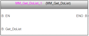
Before executing this function, please execute Command 205 to obtain the planned motion path from Mech-Viz.
Please deploy the Mech-Viz project based on the template project and set the corresponding suction cup configuration file. The template project is the suction_zone project stored in Mech-Center/tool/viz_project in the installation directory where Mech-Vision and Mech-Viz are installed.
In the parameters of the Set DO List Step:
-
Select “Standard Interface” under “Receiver”
-
Select “Get DO List from ‘Vision Move’”
-
In the drop-down list of the “Select ‘Vision Move’” parameter, select a “Vision Move” Step that needs the DO signal list
Input parameters
| Name | Description |
|---|---|
Get_DoList |
Trigger signal |
Trigger signal
Obtain the planned DO Signal list when a rising edge occurs.
Returned Data from the FromCamera Global Tag
FromCamera.STATUS_CODE: Status code
If there is no error, status code 2102 will be returned. Otherwise, the corresponding error code will be returned.
FromCamera.DO_LIST: DO Signal list
64 DO signal values are located at the tail of the returned data. The signal values are integers.
Value range: 0–999.
Placeholder value: -1.

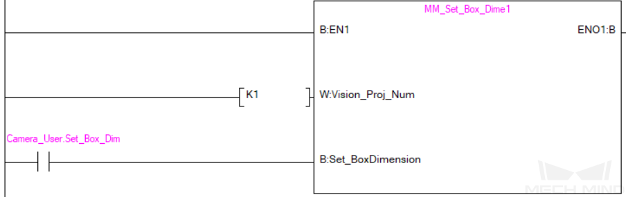
Command 501: Input Object Dimensions to Mech-Vision
This function is used for dynamically inputting object dimensions into the Mech-Vision project. Please check the actual object dimensions before running the Mech-Vision project.
The Mech-Vision project should contain the “Read Object Dimensions” Step, and the Read Sizes from Properties checkbox of this Step should be selected.
Input parameters
| Name | Description |
|---|---|
Vision_Proj_Num |
Mech-Vision Project ID |
External_Input_Box_Dimension |
Object Dimensions |
Set_Box_Dimension |
Trigger signal |
Mech-Vision Project ID
The Project ID of the Mech-Vision project to be triggered; you can check the project ID before the project name in the Project List panel in Mech-Vision.
Object Dimensions
The object dimensions (length, width, height) to be inputted to the Mech-Vision project. The dimensions will be read into the “Read Object Dimensions” Step.
Unit: mm
|
Multiply dimension values by 10000 and then assign them External_Input_Box_Dimension. |
|
External_Input_Box_Dimension here and External_Input_Pose in the function MM_Set_Pose correspond to the same EXT_INPUT_DATA tag of the ToCamera struct. If the set values are different, they cannot take effect at the same time. |
Trigger signal
Input the object dimensions in the Mech-Vision project dynamically when a rising edge occurs.
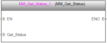
Command 901: Get Software Status
This function is designed for obtaining the execution status of Mech-Vision, Mech-Viz, and Mech-Center.
Currently, this function is capable of checking whether Mech-Vision is ready to run projects.
Input parameters
| Name | Description |
|---|---|
Get_Status |
Trigger signal |
Trigger signal
Check whether it is ready to run projects when a rising edge occurs.
Returned Data from the FromCamera Global Tag
FromCamera.STATUS_CODE: Status code
Software status. Status code 1101 indicates that Mech-Vision is ready to run projects. Other status code indicates that Mech-Vision is not ready. The function is currently capable of checking whether Mech-Vision is ready to run projects.
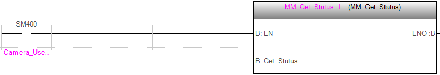
Example
When Camera_User.Get_Status is at the rising edge, this example checks the status code and stores it in the FromCamera.STATUS_CODE.
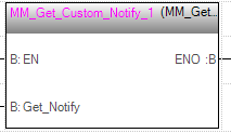
Command 601: Get Message from Notify Step
After the Mech-Vision or Mech-Viz project is triggered, this function can be called to get message from the “Notify” Step.
| When the “Notify” Step is executed in the Mech-Vision or Mech-Viz project, the message remains in the buffer of the vision system for only 1 second. Therefore, users should consider the timing of calling this function to ensure successful message retrieval. Additionally, after the PLC receives the message, the program should trigger the variable ToCamera.CLEAR_NOTIFY to clear the register data. |
Returned Data from the FromCamera Global Tag
-
NOTIFY_MSG: The message from the “Notify” Step, which is an integer.
Example
For example, the message set in the “Notify” Step is 777, and the PLC is obtaining a message in the automatic mode.
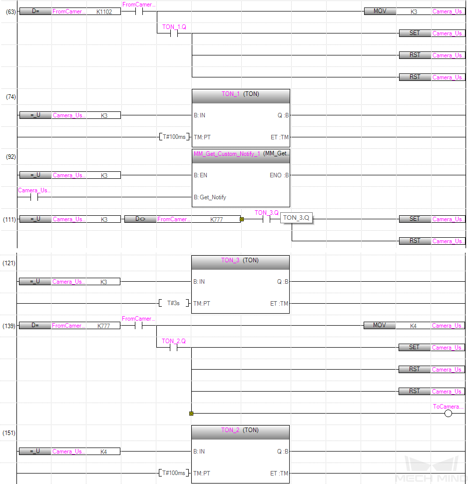
Example Description
In this example, when Camera_User.Step_Num is set to 3 in the automatic mode, the value of FromCamera.NOTIFY_MSG is not 777. After the MM_Get_Custom_Notify function is enabled, when the Camera_User.Get_Notify variable is at the rising edge, the program retrieves the message from the “Notify” Step. If the message retrieval was successful, the value of FromCamera.NOTIFY_MSG changes to 777. Otherwise, if the value remains unchanged, the PLC will prompt an error after 3 seconds.