Master-Control Communication Setup
This guide shows you how to set up Master-Control communication with a DOBOT robot.
Preparation
Check Controller and Software Compatibility
-
Controller software version: 3.5.2 or above.
-
Mech-Vision & Mech-Viz versions: 1.6.0 or above
Set up the Network Connection
Connect the Hardware
Plug one end of the Ethernet cable into the network port of the IPC and the other end into the network port of the robot controller.

① is the network port of the robot controller.
Set the IP Address
To allow communication between the IPC and the robot controller, the IPC’s network port connected to the robot controller should be in the same subnet as the robot. This means that the network portions and subnet masks of the IP addresses should be the same. For example, 192.168.100.1/255.255.255.0 and 192.168.100.2/255.255.255.0 are in the same subnet.
-
Set Camera IP Address.
-
Set Robot IP address.
-
If the robot controller software is DobotSCStudio, set the IP address according to the following steps.
In DobotSCStudio, go to .
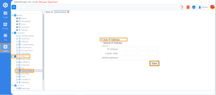
If the IP address isn’t in the same subnet as the IPC, select Manual IP Address, set the IP address manually, and save the settings. -
If the robot controller software is DobotStudio, set the IP address according to the following steps.
In DobotStudio, go to , enter the IP address, netmask and default gateway, and click Apply.

-
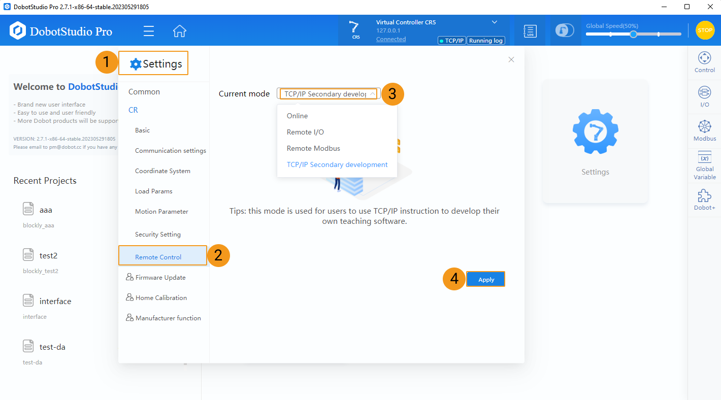
Switch to Remote Control Mode (only required by DobotStudio software)
In DobotStudio, click , select TCP/IP Secondary development for Current mode, and click Apply.
Notes
-
Do NOT use Mech-Viz and DobotSCStudio/DobotStudio software at the same time. Otherwise, Mech-Viz may not connect to the robot properly.
-
Do not use Mech-Viz when operating the teach pendant.
-
It is suggested to remove the Wi-Fi USB device connected to the controller since the device may affect remote control.
-
When master-controlling the DOBOT robot, Mech-Viz does not support setting the robot’s TCP during the project. Therefore, please make sure that the TCP value on the robot side is consistent with the TCP set in Mech-Viz. Otherwise, the real robot’s linear move path will differ from the planned path of Mech-Viz. Users can perform the following steps to make the TCP values consistent:
-
Modify the TCP value on the robot side manually to match the TCP set in Mech-Viz;
-
Move the Robot;
-
Reconnect the robot to Mech-Viz.
-
-
The DI value of the DOBOT robot is one greater than that in Mech-Viz. For example, DI1 of the real robot corresponds with DI0 in Mech-Viz.
Test Master-Control Communication
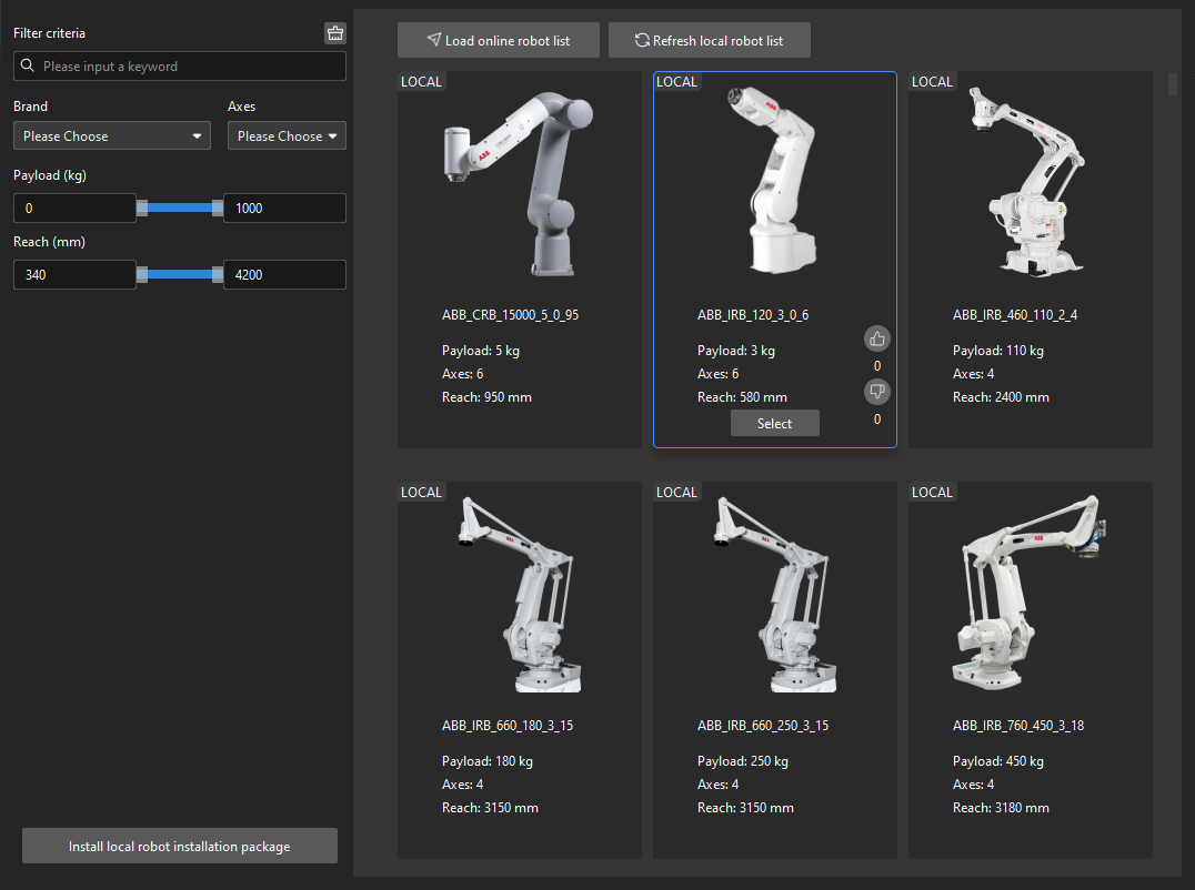
Create a Mech-Viz Project
-
Open Mech-Viz, press Ctrl+N on the keyboard to create a new project. Select the robot model corresponding to your real robot brand and model on the interface as shown below.
-
Press Ctrl+S and create or select a folder to save the project.
-
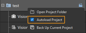
Right-click the project name in the left panel in Mech-Viz and select Autoload Project.
Connect to the Robot
-
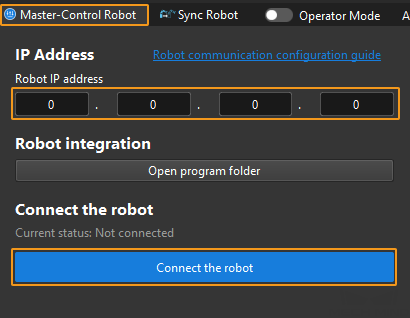
Click Master-Control Robot on the toolbar of Mech-Viz.
-
Input the IP address of the real robot in Robot IP address (the IP address in the picture is only an example). Click Connect the robot.
If Mech-Viz successfully connects the real robot, the current status will change to Connected. Meanwhile, the icon in the toolbar will turn from blue to green.
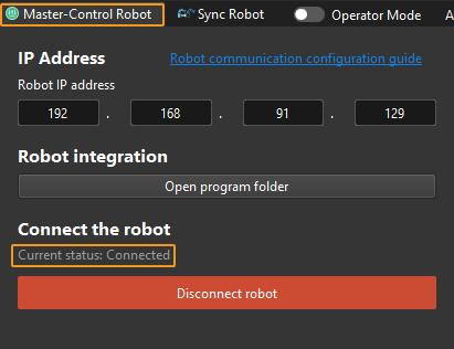
If the connection fails, please double-check the robot IP address.
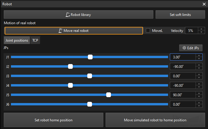
Move the Robot
-
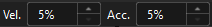
In the toolbar of Mech-Viz, change the “Vel.” (velocity) and “Acc.” (acceleration) parameters to 5%.
-
Click Sync Robot in the toolbar, and you can synchronize the poses of the simulated robot in the 3D simulation space with the poses of the real robot. Then click Sync Robot again to unselect it.

-
In the Robot tab, slightly adjust the value of “J1”, for example, from 0˚ to 3˚. This operation will move the simulated robot.
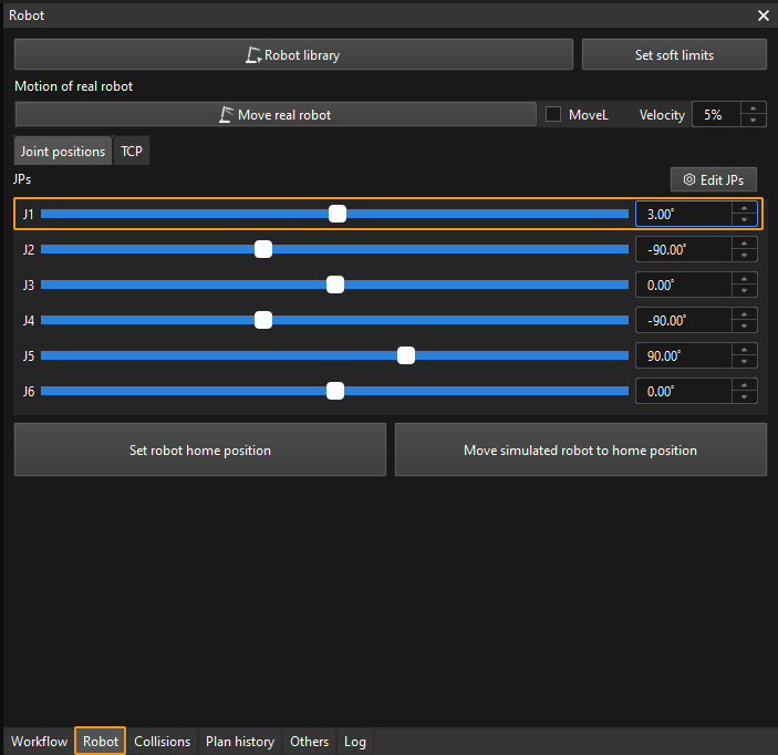
-
Click Move real robot and check if the real robot has moved. If the real robot has reached the JPs set for the simulated robot, the master-control communication is working.
When moving the robot, please ensure the safety of personnel. In the case of an emergency, press the emergency stop button on the teach pendant!