KUKA Standard Interface Subprograms
The KUKA Standard Interface provides the following subprograms:
-
Multiple parameters should be separated by commas.
-
Variable-type parameters should use local variables, which take effect only in the program.
-
Parameters can be defined as IN parameters or OUT parameters.
The KUKA Standard Interface provides the following subprograms.
Initialize Communication
This subprogram sets the name of the XML file used for setting up the TCP/IP communication, flag for successful communication, flag for successful data reception, and wait time before the program stops trying to establish the communication.
Parameters
| Name | Description |
|---|---|
IN parameters |
|
XML_Name[] |
Name of the XML file, case-sensitive. |
Alive_Flag |
ALIVE flag number in the XML file. When the flag is set to ON, the communication is successfully established. |
Recv_Flag |
RECEIVE flag number in the XML file. When the flag is set to ON, the robot has successfully received data. |
Time_Out |
Wait time in seconds before stopping connection attempt. |
Start Mech-Vision Project
This subprogram is for applications that use Mech-Vision. It runs the corresponding project to acquire and process data. It applies for applications that use Mech-Vision but not Mech-Viz.
Parameters
| Name | Description |
|---|---|
IN parameters |
|
Job |
Mech-Vision project ID, which can be viewed before the project name in the Project List panel in Mech-Vision. |
Pos_Num_Need |
The expected number of vision points for Mech-Vision to send. The vision point contains the vision pose, corresponding point cloud, label, scaling, etc. Value range: 0–20, in which 0 indicates that all vision points will be received. |
SendPos_Type |
The type of the robot pose to be sent to Mech-Vision. Value range: 0 to 3.
|
MM_J |
E6AXIS variable for storing the joint positions of the start point when SendPose_Type = 3. |
Get Vision Target(s)
This subprogram is for applications that use Mech-Vision but not Mech-Viz. It obtains the vision result from the corresponding Mech-Vision project.
Parameters
| Name | Description |
|---|---|
IN parameters |
|
Job |
Mech-Vision project ID, which can be viewed before the project name in the Project List panel in Mech-Vision. |
OUT parameters |
|
Pos_Num |
Variable for storing the number of received vision points. |
MM_Status |
Variable for storing the status code. Please see Status Codes and Troubleshooting for detailed information. |
Start Mech-Viz Project
This subprogram is for applications that use both Mech-Vision and Mech-Viz. It starts the Mech-Viz project that triggers the corresponding Mech-Vision project, and therefore the Mech-Viz project can plan the robot path based on the vision points received from Mech-Vision.
Parameters
| Name | Description |
|---|---|
IN parameters |
|
SendPos_Type |
Robot pose type. Value range: 0 to 2.
|
MM_J |
E6AXIS variable for storing the joint positions of the start point when SendPose_Type = 2. |
Get Planned Path from Mech-Viz
This subprogram obtains the planned path from Mech-Viz.
Parameters
| Name | Description |
|---|---|
IN parameters |
|
Jps_Pos |
This parameter specifies the type of waypoint pose to be obtained. The value is 1 or 2.
|
OUT parameters |
|
Pos_Num |
Variable for storing the number of received vision points. |
VisPos_Num |
Variable for storing the position of the first Vision Move waypoint in the path. For example, in the workflow “Fixed-Point Move 1, Fixed-Point Move 2, Vision Move 1, Fixed-Point Move 3”, the position of the first Vision Move waypoint is 3. If the path does not contain Vision Move waypoint, the returned value is 0. |
MM_Status |
Variable for storing the status code. Please see Status Codes and Troubleshooting for detailed information. |
Example
MM_Get_VizData(2,Pose_Num,VisPos_Num,Status)This example obtains the planned path from Mech-Viz in the form of TCP. The number of poses received is stored in the variable Pos_Num, the position of the Vision Move waypoint is stored in the variable VisPos_Num, and the received status code is stored in variable Status.
Obtain Vision Point Pose
This subprogram stores a vision pose returned by Mech-Vision or a waypoint pose (as a TCP) returned by Mech-Viz in the specified variable.
Parameters
| Name | Description |
|---|---|
IN parameters |
|
Serial |
Specify the index of the pose to be stored. |
OUT parameters |
|
MM_P |
P variable for storing the specified pose. |
MM_Label |
Variable for storing the label corresponding to the specified set of joint positions. |
MM_Speed |
Variable for storing the velocity corresponding to the specified set of joint positions. |
Obtain Joint Positions (Available when Mech-Viz is used)
This subprogram stores a vision pose returned by Mech-Vision or the JPs of a waypoint returned by Mech-Viz in the specified position variable.
Parameters
| Name | Description |
|---|---|
IN parameters |
|
Serial |
Specify the index of the pose to be stored. |
OUT parameters |
|
MM_J |
Variable for storing the specified set of joint positions. |
MM_Label |
Variable for storing the label corresponding to the specified set of joint positions. |
MM_Speed |
Variable for storing the velocity corresponding to the specified set of joint positions. |
Switch Mech-Vision Recipe
This subprogram specifies which parameter recipe of the Mech-Vision project to use. Parameter recipes can be used to switch parameter settings, including point cloud model for matching, ROI, confidence threshold, etc, in the same Mech-Vision project when it is used to recognize different workpieces. This subprogram must be called BEFORE MM_Start_Vis.
Select Mech-Viz Branch
This subprogram is used to select along which branch the Mech-Viz project should proceed. Such branching is achieved by adding Branch by Msg Step(s) to the Mech-Viz project. This subprogram specifies which exit port such Step(s) should take. MM_Start_Viz should be called BEFORE this subprogram. When executing the “Branch by Msg” Step, Mech-Viz waits for the exit port No. sent by Command 203.
Parameters
| Name | Description |
|---|---|
IN parameters |
|
Branch_Num |
Step ID of the “Branch by Msg” Step. Its value is an integer. The Step ID can be viewed in the Step Parameters panel. |
Export_Num |
The number of the exit port to take plus 1. For example, to select exit port 0 in Mech-Viz, set the value of this parameter to 1. Value range: 1 to 99. |
Set Move Index
This subprogram sets the index value for move-type Steps that contain index parameters. These Steps include Move by List, Move by Grid, Custom Pallet Pattern, and Predefined Pallet Pattern. MM_Start_Viz must be called BEFORE this subprogram.
Parameters
| Name | Description |
|---|---|
IN parameters |
|
Skill_Num |
ID of the Step, an integer. The Step ID can be viewed in the Step Parameters panel. |
Index_Num |
The index value that should be set the next time this Step is executed. When this subprogram is sent, the current index value in Mech-Viz will become the parameter value minus 1. When the Mech-Viz project runs to the Step specified by this subprogram, the Current Index value in Mech-Viz will be increased by 1 to become the parameter’s value. |
Get Software Status
This subprogram is used to obtain the software execution status of Mech-Vision, Mech-Viz, and Mech-Center. Currently, this subprogram can only be used to check whether Mech-Vision is ready to run.
Parameters
| Name | Description |
|---|---|
OUT parameters |
|
MM_Status |
Variable for storing the status code. Please see Status Codes and Troubleshooting for detailed information. |
Input Object Dimensions to Mech-Vision
This subprogram is used to dynamically input object dimensions into the Mech-Vision project. This subprogram must be called BEFORE MM_Start_Vis.
Get Gripper DO List
This subprogram obtains the gripper DO list planned by Mech-Vision or Mech-Viz. To apply the DO signals to the gripper, call the mm_set_dolist subprogram.
Set Gripper DO List
This subprogram sets the obtained DO signals to the robot’s gripper.
| MM_Get_DoList must be called BEFORE this subprogram. |
Calibration
This subprogram is used for hand-eye calibration (camera extrinsic parameter calibration). It automates the calibration process in conjunction with the Camera Calibration subprogram in Mech-Vision.
Parameters
| Name | Description |
|---|---|
IN parameters |
|
Move_Type |
The move type of the robot, 1 or 2. 1: MoveL. 2: MoveJ. |
PosJps |
Pose as flange pose or joint positions, 1 or 2. 1: Flange pose. 2: Joint positions. |
WaitTime |
The time the robot waits to avoid shaking after it moves to the calibration point; the default value is 2 (s). |
E1 |
Data of the external 7th axis in mm. |
Get Custom Output Data from Mech-Vision
This subprogram is used to obtain the vision result that includes custom port outputs from the corresponding Mech-Vision project. “Custom port outputs” refers to data output by ports other than poses and labels of the “Procedure Out” Step. The output ports can be customized if the Port Type parameter of the Step is set to “Custom”.
Save Custom Output data of Mech-Vision to Specified Variables
This subprogram stores the data in a vision point returned by Mech-Vision in the specified variables. This subprogram should be called AFTER Mech-Vision MM_Get_Dy_Data.
Parameters
| Name | Description |
|---|---|
IN parameters |
|
Serial |
Specify the index of the vision point whose custom data need to be obtained. |
OUT parameters |
|
MM_P |
Variable for storing the pose in the specified vision point. |
MM_Label |
REAL-typed variable for storing the label in the specified vision point. |
MM_UserData |
Predefined global variable for storing the custom port outputs in the specified vision point. The maximum length is 50. |
Get Vision Move Data or Custom Output Data
This subprogram obtains the Vision Move output from the Mech-Vision project, or the Vision Move output or custom output from the Mech-Viz project.Call MM_Get_PlanPose or MM_Get_PlanJps to assign the received data to variables.
Parameters
| Name | Description |
|---|---|
IN parameters |
|
Resource |
This parameter specifies the source of the Vision Move output.
|
Jps_Pos |
This parameter specifies the returned data format. Details are provided below. |
OUT parameters |
|
Pos_Num |
Variable for storing the number of received waypoints. |
VisPos_Num |
Variable for storing the position of the first Vision Move waypoint in the path. |
MM_Status |
Variable for storing the status code. |
-
When the value of Resource is 0, the valid value range of Jps_Pos is 1 to 4. Details are provided below.
Value of Jps_Pos Format of returned data (Explained below) 1
Pose (joint positions), motion type, tool ID, velocity, element 1 in custom output data, … element N in custom output data
2
Pose (TCP), motion type, tool ID, velocity, element 1 in custom output data, … element N in custom output data
3
Pose (joint positions), motion type, tool ID, velocity, Mech-Viz Vision Move data, element 1 in custom output data, … element N in custom output data
4
Pose (TCP), motion type, tool ID, velocity, Mech-Viz Vision Move data, element 1 in custom output data, … element N in custom output data
-
When the value of Resource is a positive integer, the valid value range of Jps_Pos is 1 to 2. Details are provided below.
Value of Jps_Pos Format of returned data (Explained below) 1
Pose (joint positions), motion type, tool ID, velocity, Mech-Vision Vision Move data
2
Pose (TCP), motion type, tool ID, velocity, Mech-Vision Vision Move data
Pose
The pose of waypoints can be either robot joint positions (JPs, measured in degrees) or tool center point (TCP, where the three-dimensional coordinates are measured in millimeters, and the Euler angles are measured in degrees), depending on the value of the parameter Jps_Pos in the subprogram called by the robot.
Motion type
-
1: Joint motion (MOVEJ)
-
2: Linear motion (MOVEL)
Tool ID
The ID of the tool to be used at this waypoint. The value “-1” means that no tool will be used at this waypoint.
Velocity
The velocity at this waypoint.
Vision Move data
Vision Move data: Refers to data output by the “Vision Move” Step in Mech-Vision or Mech-Viz, including labels of picked workobjects, number of picked workobjects, number of workobjects to be picked this time, edge/corner ID of vacuum gripper, TCP offset, orientation of workobject group, orientation of workobject, dimensions of workobject group.
Element in custom output data
“Custom output data” refers to the data output by ports other than poses and labels of the “Procedure Out” Step in the Mech-Vision project. The output ports can be customized if the “Port Type” parameter of the Step is set to “Custom”. The custom port outputs are arranged in alphabetical order of the custom port names.
Example
MM_GET_PLANDATA(0,2,Pose_Num,VisPos_Num,Status)This example obtains the planned path that includes custom port outputs from Mech-Viz, and the value of Jps_Pos is 2. The number of waypoints received is stored in Pose_Num. The position of the Vision Move waypoint is stored in VisPose_Num. The status code is stored in Status.
Save Waypoint to Specified Variables
This subprogram is called AFTER MM_GET_PLANDATA to store the obtained data in variables. The obtained values are assigned to different variables based on the value of the Jps_Pos parameter in the MM_GET_PLANDATA subprogram.
Subprogram
MM_Get_PlanPose(Serial:IN,Jps_Pos:IN,MM_P:OUT,MM_MoveType:OUT,MM_ToolNum:OUT,MM_Speed:OUT) (When the value of Jps_Pos is 2 or 4)
MM_Get_PlanJps(Serial:IN,Jps_Pos:IN,MM_J:OUT,MM_MoveType:OUT,MM_ToolNum:OUT,MM_Speed:OUT)  (When the value of Jps_Pos is 1 or 3)
Parameters
| Name | Description |
|---|---|
IN parameters |
|
Serial |
Specify the index of the waypoint to be stored. |
Jps_Pos |
The same as the value of Jps_Pos in the Get Vision Move Data or Custom Output Data subprogram. |
OUT parameters |
|
MM_P |
Variable for storing the TCP in the specified waypoint. |
MM_J |
Variable for storing the joint positions in the specified waypoint. |
MM_MoveType |
Variable for storing the motion type in the specified waypoint. 1 stands for joint motion, and 2 stands for linear motion. |
MM_ToolNum |
Variable for storing the tool ID in the specified waypoint. The value “-1” means that no tool will be used at this waypoint. |
MM_Speed |
Variable for storing the velocity in the specified waypoint. |
MM_UserData |
Predefined global variable for storing the custom port outputs in the specified waypoint. The size of the array is 50. |
MM_Plan_Results |
Predefined global variable for storing the Vision Move data in the specified waypoint. The size of the array is 21. |
Content of the MM_Plan_Results array is explained in the table below.
| Value | Description | Variable |
|---|---|---|
Labels of picked workobjects |
Consists of 10 integers. By default, its value is ten 0s. |
MM_Plan_Results[1] ~ MM_Plan_Results[10] |
Number of picked workobjects |
The total number of workobjects that have been picked. |
MM_Plan_Results[11] |
Number of workobjects to be picked this time |
Number of workobjects to be picked this time |
MM_Plan_Results[12] |
Edge/corner ID of vacuum gripper |
The ID of the edge/corner used to pick workobjects this time. |
MM_Plan_Results[13] |
TCP offset |
The XYZ offset between the center of the workobject group and the tool center point. |
MM_Plan_Results[14] ~ MM_Plan_Results[16] |
Orientation of workobject group |
The relative position between the workobject group and the length of the vacuum gripper. The value is 0 or 1, where 0 stands for parallel and 1 for vertical. |
MM_Plan_Results[17] |
Orientation of workobject |
The relative position between the length of a workobject and that of the vacuum gripper. The value is 0 or 1, where 0 stands for parallel and 1 for vertical. |
MM_Plan_Results[18] |
Dimensions of the workobject group |
The length, width and height of the workobject group to be picked this time. |
MM_Plan_Results[19] ~ MM_Plan_Results[21] |
Example
-
Example 1
MM_Get_PlanPose(1,4,XP1,MoveType,ToolNum,Pose_Speed)This example stores the TCP in the first received waypoint to XP1, the corresponding motion type to MoveType, the corresponding tool ID to ToolNum, the corresponding velocity to Pose_Speed, the corresponding custom port outputs to MM_UserData, and the corresponding Vision Move data to MM_Plan_Results.
-
Example 2
MM_Get_PlanJps(1,3,JP1,MoveType,ToolNum,Pose_Speed)This example stores the joint position in the first received waypoint to P1, the corresponding motion type to MoveType, the corresponding tool ID to ToolNum, the corresponding velocity to Pose_Speed, the corresponding custom port outputs to MM_UserData, and the corresponding Vision Move data to MM_Plan_Results.
Get Result of Step “Path Planning” in Mech-Vision
This subprogram obtains the collision-free path planned by the “Path Planning” Step from the corresponding Mech-Vision project.
The Port Type parameter of the “Procedure Out” Step in the Mech-Vision project must be set to “Predefined (robot path)”.
Parameters
| Name | Description |
|---|---|
IN parameters |
|
Job |
Mech-Vision project ID, which can be viewed before the project name in the Project List panel in Mech-Vision. |
Jps_Pos |
The pose type of waypoints returned by the “Path Planning” Step.
|
OUT parameters |
|
Pos_Num |
Variable for storing the number of received waypoints. |
VisPos_Num |
Variable for storing the position of the first Vision Move waypoint in the path. For example, if the path is composed of Steps Fixed-Point Move_1, Fixed-Point Move_2, Vision Move and Fixed-Point Move_3 sequentially, the position of Vision Move is 3. If the path does not contain “Vision Move”, the value of this parameter is 0. |
MM_Status |
Variable for storing the status code. |
Example
MM_GET_VISPATH(1,1,Pose_Num,VisPos_Num,Status)This example obtains the planned path from Mech-Vision project No.1 in the form of joint positions.The number of waypoints is stored in Pos_Num, the position of the Vision Move waypoint is stored in VisPos_Num, and the status code is stored in Status.
Read Mech-Viz Step Parameter
This subprogram reads the parameter value of a specific Step in the Mech-Viz project.
Parameters
| Name | Description |
|---|---|
IN parameters |
|
Get_id |
This parameter corresponds to the Config ID field defined in the property_config file. |
OUT parameters |
|
MM_Status |
An integer variable used to store the status code. |
Viz_Prop |
An integer variable used to store the returned parameter value of the specified Step. |
|
From the toolbar of Mech-Vision, go to . Click Property Configuration to open the property_config file. 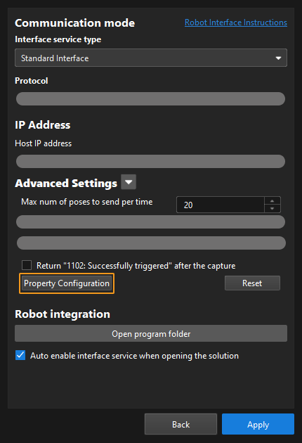
|
Before calling this function, users should define a Config ID and its corresponding Step ID and parameter key name in the following format in the property_config file.
read, Config ID, Step ID, parameter key name
read |
Indicates that this line is used to read the parameter value of a Step. |
Config ID |
Specifies a unique ID, which in a positive integer. One Config ID corresponds to only one parameter value of a Step. To read multiple parameter values, you should set different Config IDs. |
Step ID |
The Step ID of the Step whose parameter is to be read. |
Parameter key name |
Specifies the key name of the parameter whose value the robot requires to read. |
|
|
The property_config file can have multiple read commands. The Config ID in these commands must be different. |
Example
In the line below, “5” is the Config ID; “3” is the Step ID; and “xCount” is the parameter key name. Add this line to the property_config file. Add this line to the property_config file.
read, 5, 3, xCountWhen the robot calls the subprogram below, it receives the value of the parameter whose key name is “xCount”.
mm_get_property(5,MM_Status,Viz_Prop)This example stores the value of the parameter whose key name is “xCount” of Step 3 in the Mech-Viz project to the Viz_Prop variable, and stores the received status code to the “MM_Status” variable.
Set Mech-Viz Step Parameter
This subprogram sets the parameter value of a specific Step in the Mech-Viz project.
Parameters
| Name | Description |
|---|---|
IN parameters |
|
Set_id |
This parameter corresponds to the Config ID field defined in the property_config file. |
OUT parameters |
|
MM_Status |
An integer variable used to store the status code. |
|
From the toolbar of Mech-Vision, go to . Click Property Configuration to open the property_config file.
|
Before sending this command, users should define a Config ID and its corresponding Step ID, parameter key name and parameter value in the following format in the property_config file.
write, Config ID, Step ID, parameter key name, parameter value
write |
Indicates that this line is used to set the parameter value of a Step. |
Config ID |
Specifies an ID, which is a positive integer and can be used repeatedly. |
Step ID |
Specifies the Step whose parameter value the robot requires to read. |
Parameter key name |
Specifies the key name of the parameter whose value the robot requires to set. |
Parameter value |
Specifies the value that the robot sets for the parameter. |
|
Example
In the line below, “1” is the Config ID, and “3” is the Step ID. “xOffset”, “yOffset” and “zOffset” are parameter key names; and “10”, “20” and “30” are their respective values. Add this line to the property_config file.
write, 1, 3, xOffset, 10
write, 1, 3, yOffset, 20
write, 1, 3, zOffset, 30
When the robot calls the subprogram below, Mech-Viz sets the values of the parameters whose key names are “xOffset”, “yOffset” and “zOffset” respectively to “10”, “20” and “30”.
mm_set_property(1,MM_Status)This example sets the values of the parameters whose key names are “xOffset”, “yOffset” and “zOffset” respectively to “10”, “20” and “30”, and stores the received status code in the “MM_Status” variable.