Master-Control Communication Setup (RobotWare 6)
This guide shows you how to set up Master-Control communication with an ABB robot.
Preparation
Check Controller and Software Compatibility
-
The robot controller is IRC5, and the version of RobotWare is 6.02 or above.
Follow the steps below to check the RobotWare version.
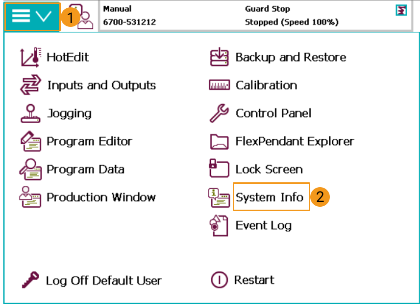
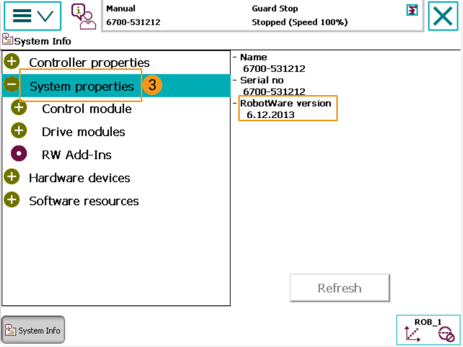
-
The following control modules should be installed:
-
623-1 Multitasking
-
616-1 PCInterface
Follow the steps below to check whether the control module options are installed.
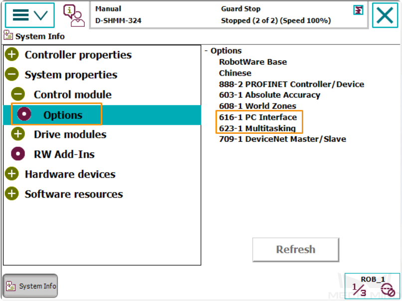
The above control module options must be installed to realize Master-Control of an ABB robot. -
Set up the Network Connection
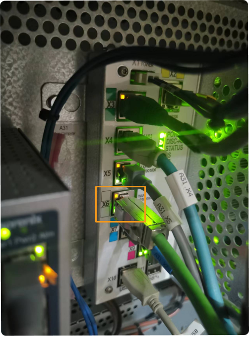
Connect the Hardware
Plug the Ethernet cable of the IPC into the X6 (WAN) port of the robot controller, as shown below.
Set the IP Address
You can set the IP on the teach pendant or via RobotStudio.
Set the IP on the teach pendant:
-
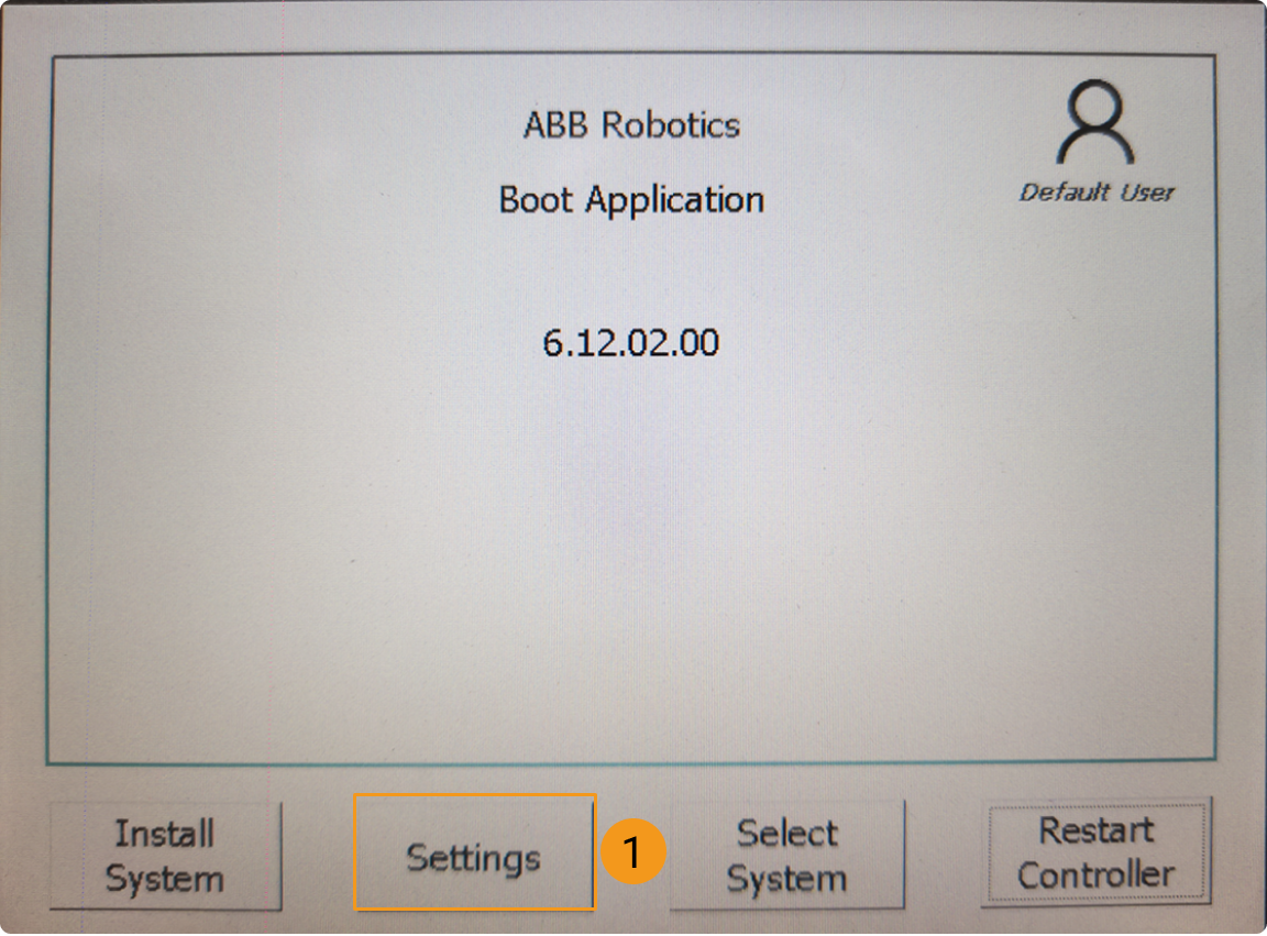
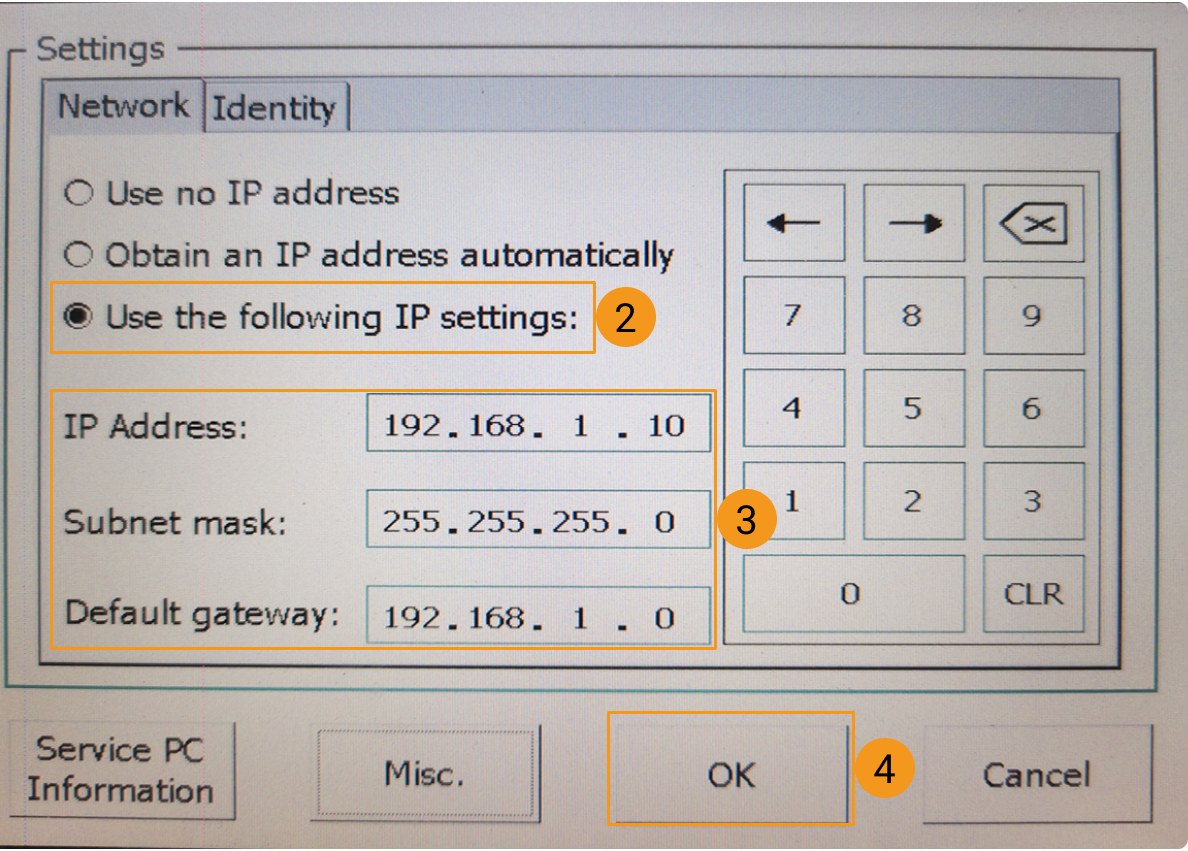
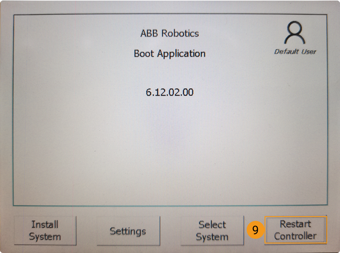
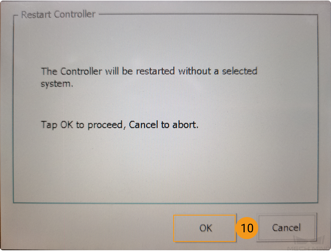
Please follow the instructions in the figure below to set the IP address.
-
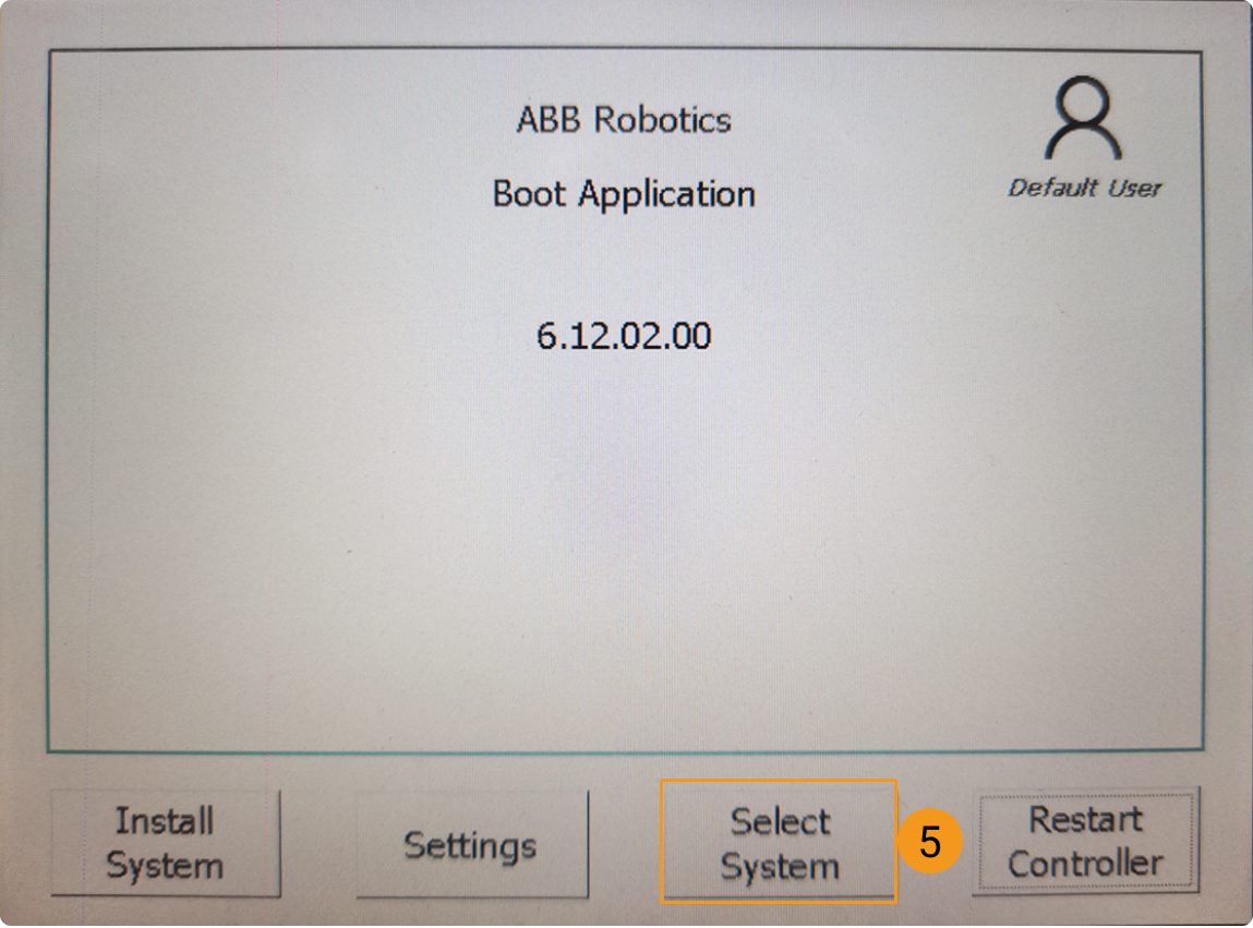
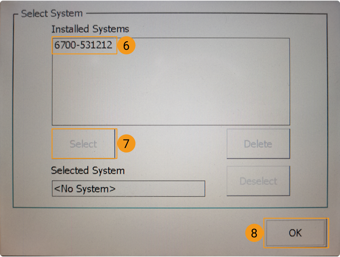
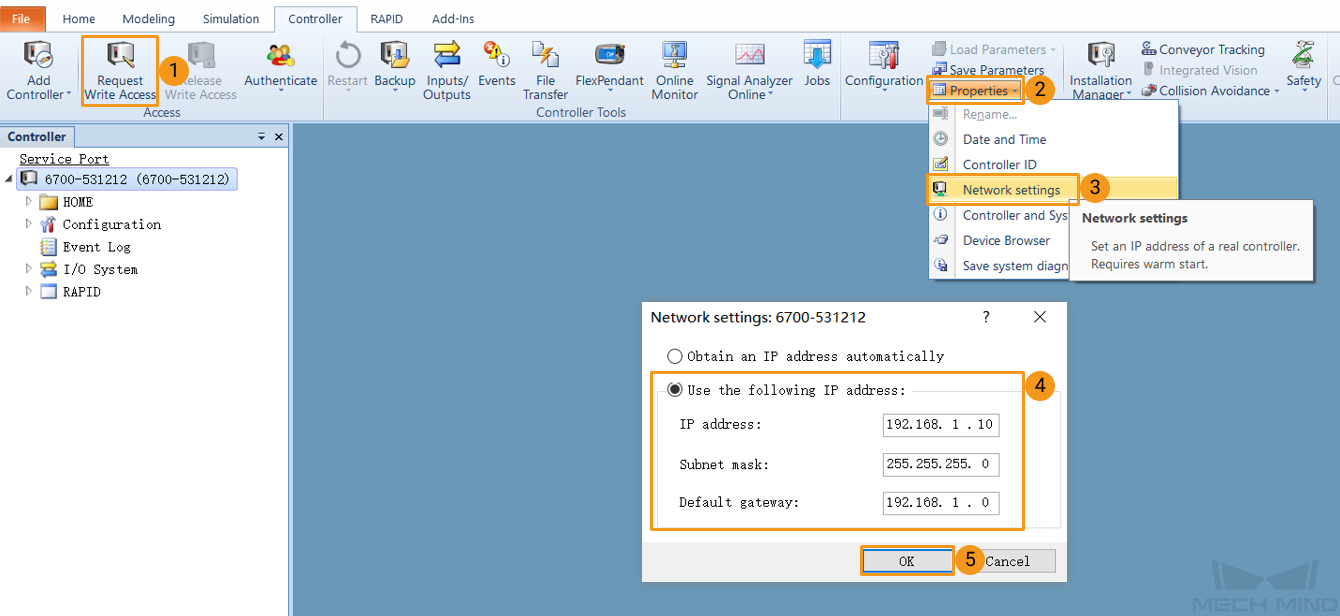
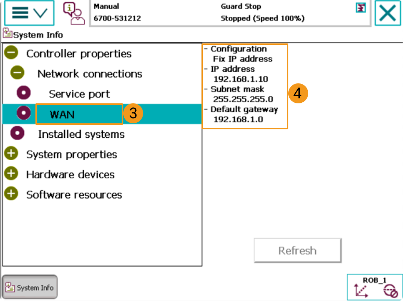
After restarting, you will see the interface as shown below. Follow the steps below to complete configuring the IP address. The IP addresses of the robot and the IPC must belong to the same subnet.
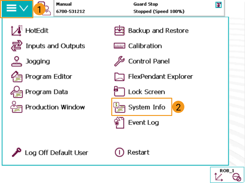
Check if the IP configuration was successful
Go to to check if the IP configuration was successful after restarting.
|
Load the Program Files to the Robot
Prepare the Files
Backup
Before operating the robot, please follow the backup instructions below to back up the system so that the robot system can be restored if an incorrect operation occurs. You can backup the robot system via the teach pendant or RobotStudio.
-
Backup on the teach pendant
-
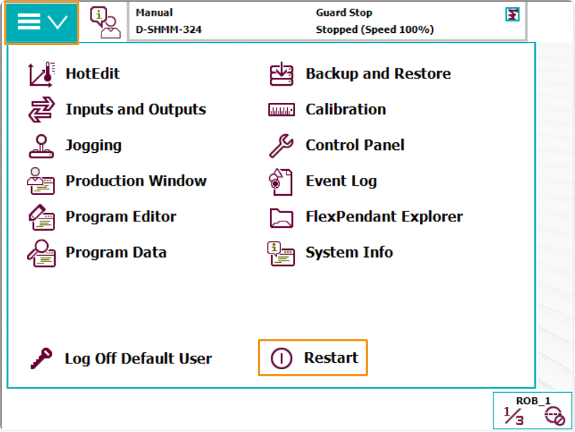
Go to the home page using the menu in the upper-left corner, and then select Backup and Restore.
-
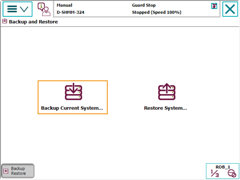
Select Backup Current System….
-
Specify the backup file name by pressing on ABC…, and specify the directory for saving the file by pressing the button below. Then, press Backup in the lower-right to start the backup process.
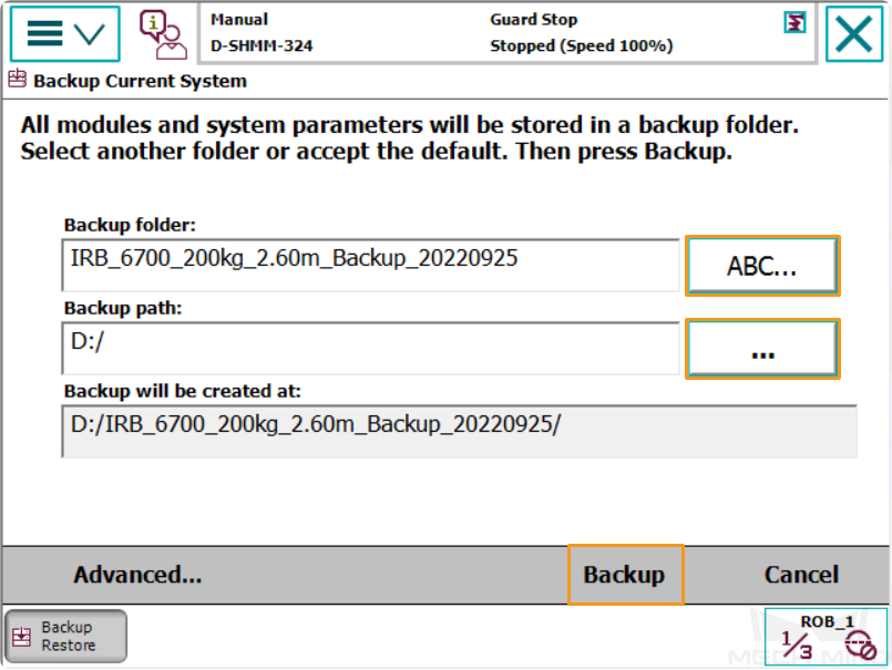
-
-
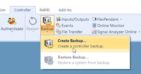
Backup in RobotStudio
-
In the main interface of RobotStudio, select the controller you want to backup, and then select .
-
In the pop-up window, confirm the backup name and location and then click OK.

-
Reset
|
There are two types of resets, which are resetting the system and resetting RAPID.
|
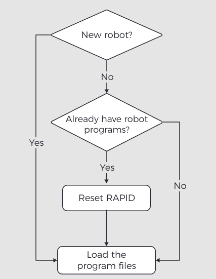
Reset RAPID
Please determine whether you should reset RAPID according to the following flowchart.
-
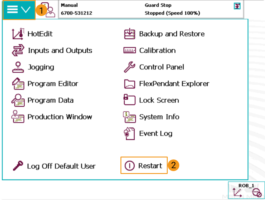
Go to the home page using the menu in the upper-left corner, and then select Restart.
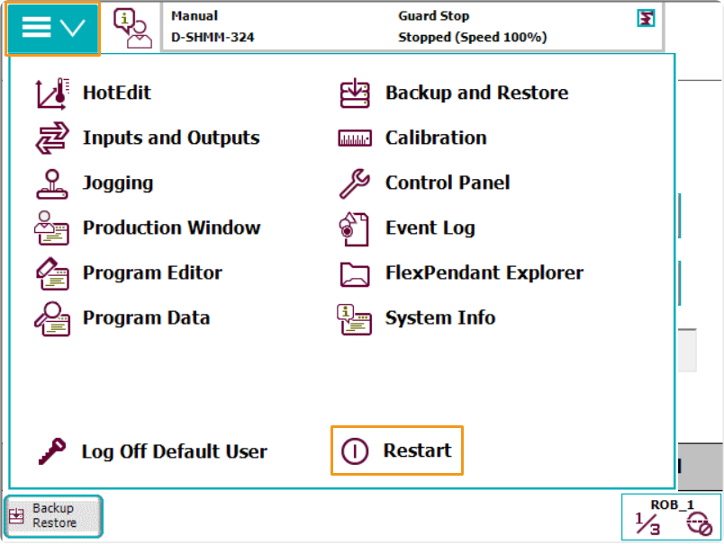
-
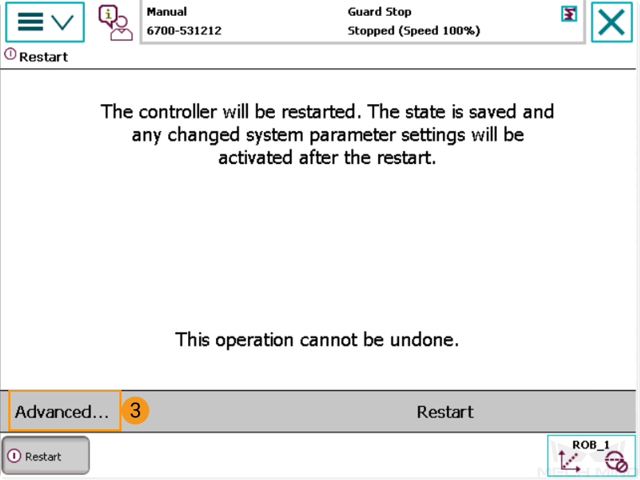
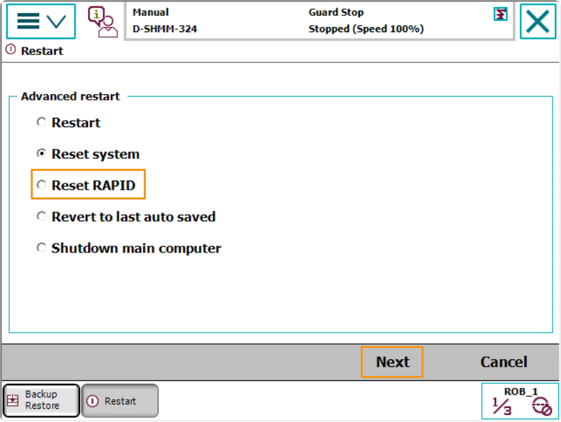
Select Advanced… in the lower-left.
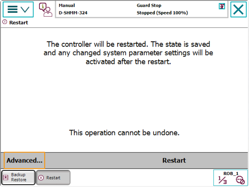
-
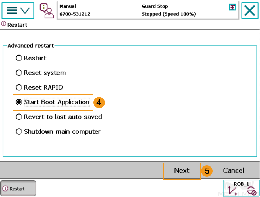
Select Reset RAPID, and then press Next in the lower-right.
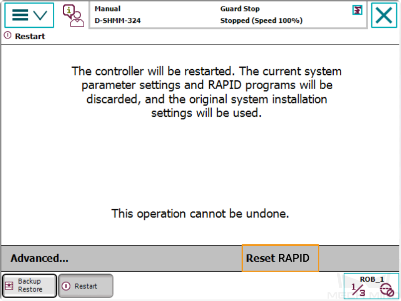
-
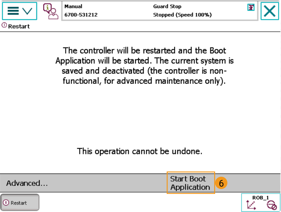
Press Reset RAPID.
Reset System
| Resetting the system will restore the factory settings. Please make sure that you have completed the backup operation. |
-
Go to the home page using the menu in the upper-left corner, and then select Restart.
-
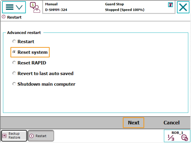
Select Advanced… in the lower-left.
-
Select Reset system, and then press Next in the lower-right.
-
Press Reset system.

Obtain the Program Files
Copy the program files into a USB flash drive. Please locate the folder where Mech-Vision and Mech-Viz are installed, and the files are stored in Mech-Center/Robot_Server/Robot_FullControl/abb/RobotWare 6.
-
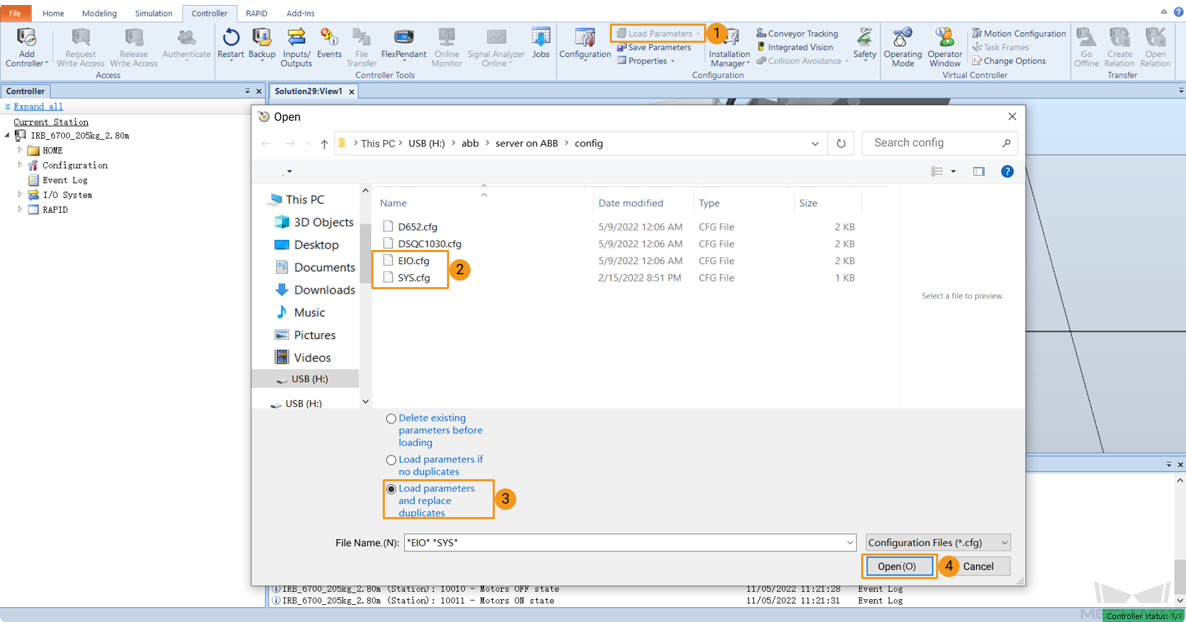
The config files in the
RobotWare 6folder should be compatible with the I/O Unit in use. Please choose the right config files from the config folders according to the actual situation.-
If a DSQC 652 I/O unit is used, please select D652.cfg and SYS.cfg.
-
If a DSQC 1030 I/O unit is used, please select DSQC1030.cfg and SYS.cfg.
-
If other I/O unit is used or the program is only used for automatic calibration, please select EIO.cfg and SYS.cfg.
-
-
In the
RobotWare 6folder, files in the MM folder are robot program modules.
Load the Files to the Robot
-
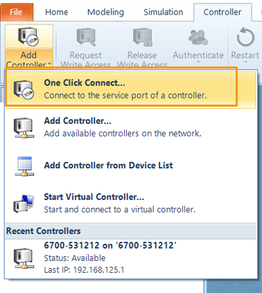
Open RobotStudio on the IPC and connect to the controller.
-
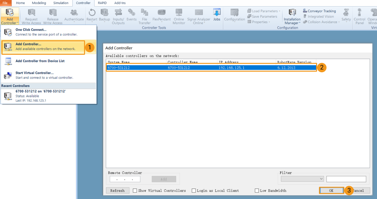
If the robot controller is connected via the LAN port, click One Click Connect….
-
If the robot controller is connected via the WAN port or a switch, click Add Controller and then select the controller and click OK. If the controller is added successfully, RobotStudio will be connected to the service port of the controller automatically.
-
-
Request write access:
Click Request Write Access to request the write access to the teach pendant.
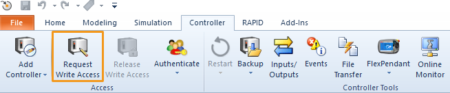
Press Grant in the Request Write Access window on the teach pendant.
-
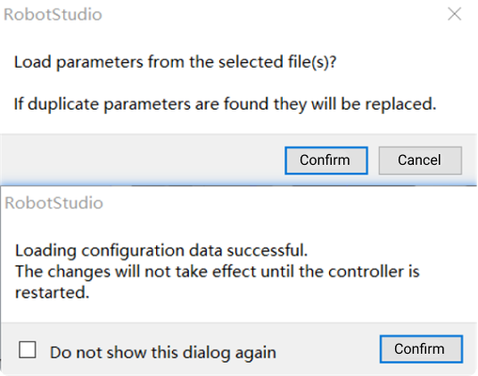
Import the config files as shown below. Click Confirm in the pop-up windows.
-
Follow the steps as shown in the figure below to copy the MM folder in the
RobotWare 6folder and paste it to the HOME directory of the robot system.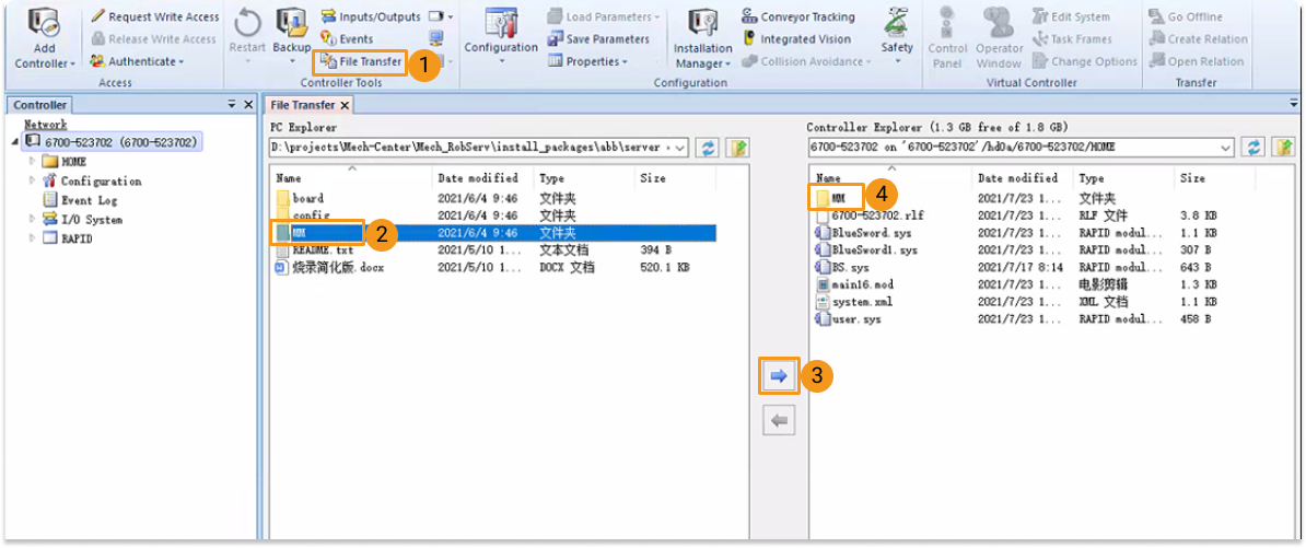
-
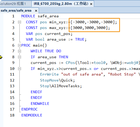
Modify the safe zone threshold (in mm) in the safe_area.mod program according to the actual on-site work space of the robot.
Configure I/O System
If an I/O unit other than DSQC 652 or DSQC 1030 is used, you should configure the robot I/O system after loading the program. Please follow the steps below to proceed:
-
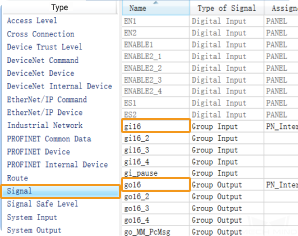
In the main interface of RobotStudio, select .

-
Locate and click Signal in the Type column, locate gi16 and go16 in the Name column on the right, and then double-click to enter the edit window.
-
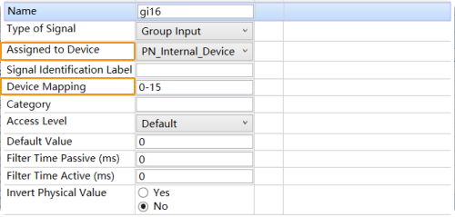
After confirming the corresponding devices and device mapping, modify the values of Assigned to Device and Device Mapping for gi16 and go16 respectively.
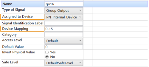
-
After the configuration, click OK. Then restart the controller to make the changes take effect.
Test Master-Control Communication
Run the Program
-
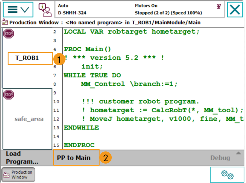
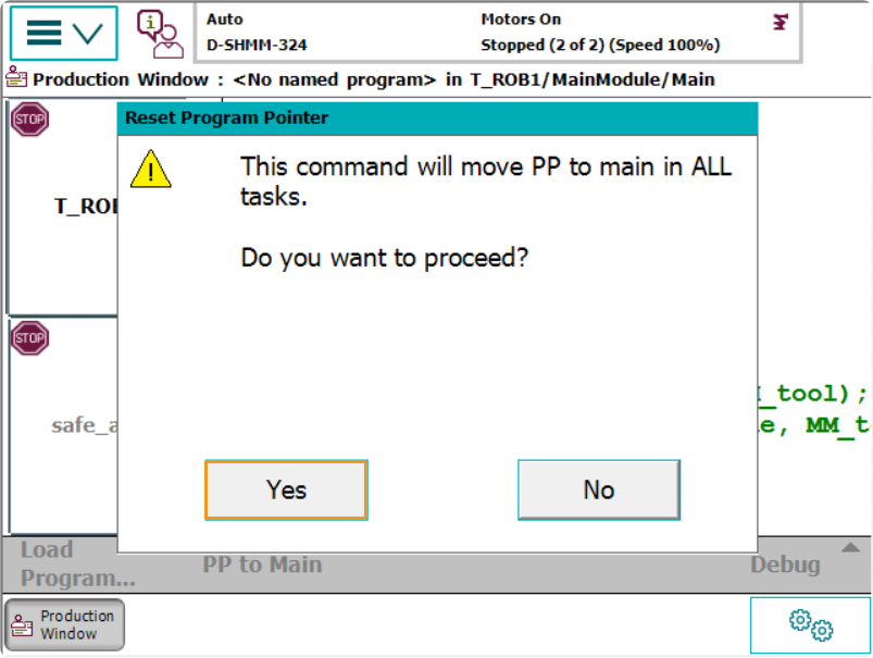
Move the PP of tasks T_ROB1 and safe_area to Main respectively. After selecting PP to Main, if a window as shown below pops up, please tap Yes to confirm.
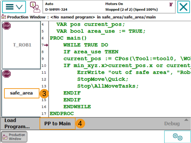
-
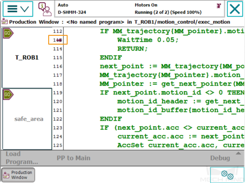
Run the program manually or automatically. The program pointer is shown in the figure below.
Create a Mech-Viz Project
-
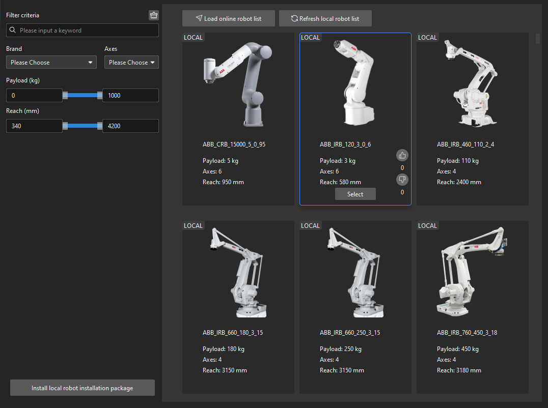
Open Mech-Viz, press Ctrl+N on the keyboard to create a new project. Select the robot model corresponding to your real robot brand and model on the interface as shown below.
-
Press Ctrl+S and create or select a folder to save the project.
-
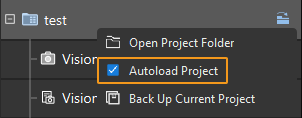
Right-click the project name in the left panel in Mech-Viz and select Autoload Project.
Connect to the Robot
-
Click Master-Control Robot on the toolbar of Mech-Viz.
-
Input the IP address of the real robot in Robot IP address (the IP address in the picture is only an example). Click Connect the robot.
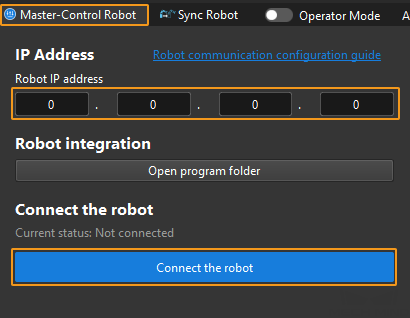
If Mech-Viz successfully connects the real robot, the current status will change to Connected. Meanwhile, the icon in the toolbar will turn from blue to green.
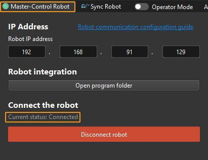
If the connection fails, please double-check the robot IP address.
Move the Robot
-
In the toolbar of Mech-Viz, change the “Vel.” (velocity) and “Acc.” (acceleration) parameters to 5%.
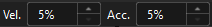
-
Click Sync Robot in the toolbar, and you can synchronize the poses of the simulated robot in the 3D simulation space with the poses of the real robot. Then click Sync Robot again to unselect it.

-
In the Robot tab, slightly adjust the value of “J1”, for example, from 0˚ to 3˚. This operation will move the simulated robot.
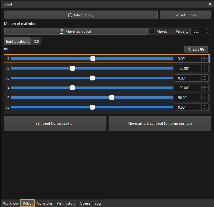
-
Click Move real robot and check if the real robot has moved. If the real robot has reached the JPs set for the simulated robot, the master-control communication is working.
When moving the robot, please ensure the safety of personnel. In the case of an emergency, press the emergency stop button on the teach pendant! 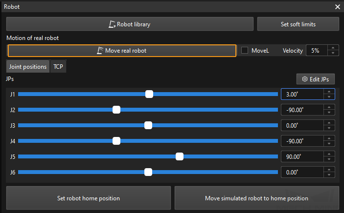
Troubleshooting
If the program has been loaded but the robot cannot be connected successfully, please check whether the following requirements have been met.
-
IPC side:
-
The firewall is turned off.
-
The IPC can communicate with the robot IP address with the ping command in the command prompt.
-
There is no interference from any antivirus software.
-
Two network ports of the IPC belong to different subnets and there is no conflict.
-
If the IPC is connected via a router, there is no interference from other network cables.
-
-
Robot side:
-
The Ethernet cable is connected to the WAN port of the controller properly.
-
The robot IP address is set correctly. Please ensure that the set IP address is that of the WAN port instead of others.
-
You have run the program on the robot side.
-