Set up Standard Interface Communication with YASKAWA
This section introduces the process of setting up the Standard Interface communication with a YASKAWA robot.
Check Controller and Software Compatibility
-
Ensure that a 6-axis YASKAWA robot is used.
-
Ensure that the robot controller and the controller system software version comply with the following requirements.
Controller Controller system software version YRC1000
YAS2.94.00-00
YRC1000micro
YBS2.31.00-00
The following instructions are based on YRC1000 (YAS2.94.00-00) controller. Details may differ for other teach pendants of the YASKAWA robot. -
Option function requirements: The MotoPlus and Ethernet functions must be enabled.
Set up the Network Connection
Connect the Hardware
For YRC1000 controller, plug the Ethernet cable into the LAN2 (CN106) port.
|
For YRC1000 controller:
|
Set the IP Address
-
Press and hold the
MAIN MENUkey and power the robot to enter the maintenance mode.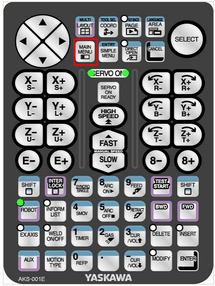
-
The system will enter the normal startup mode if you do not press the
MAIN MENUkey. -
If the robot is already started, please restart the robot while pressing the
MAIN MENUkey.
-
-
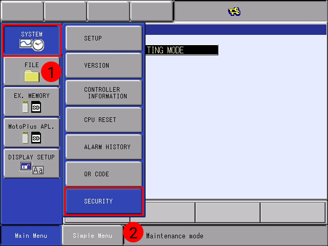
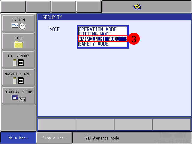
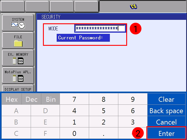
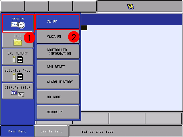
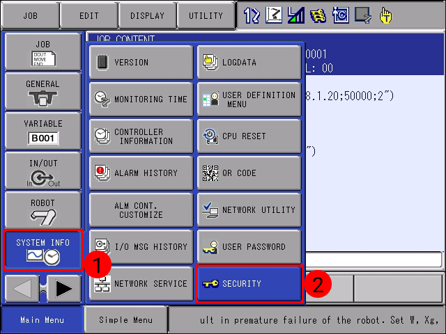
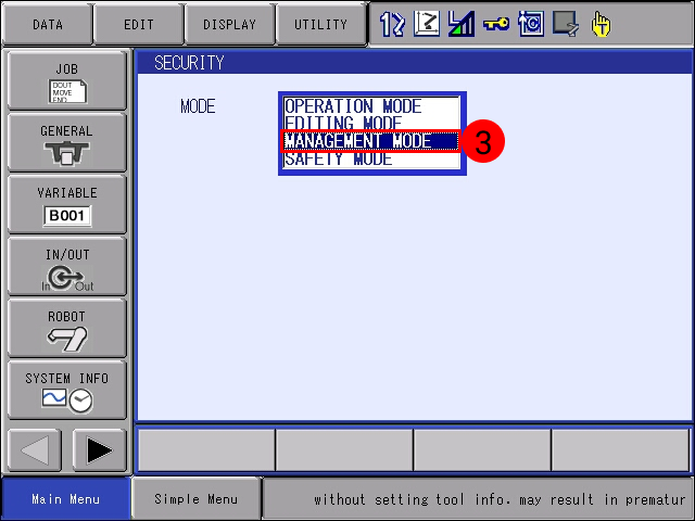
Select . Then select MANAGEMENT MODE.
-
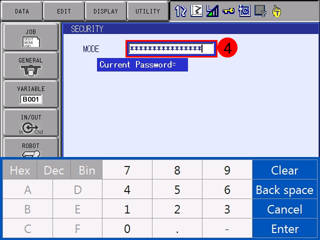
Enter the password (the default password is sixteen 9s), and then click Enter to enter MANAGEMENT MODE.

-
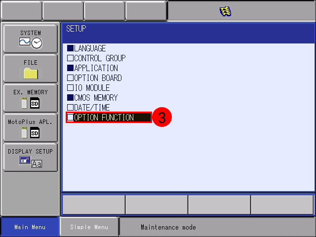
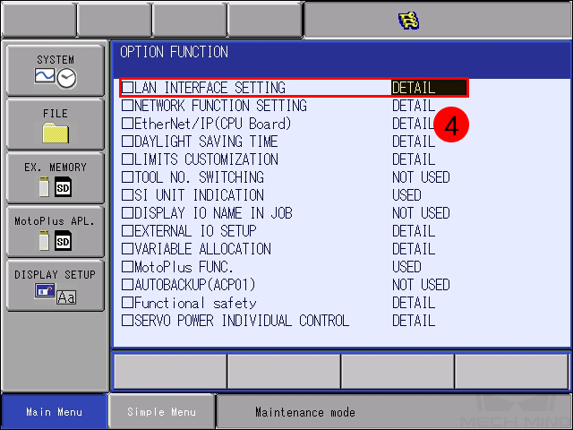
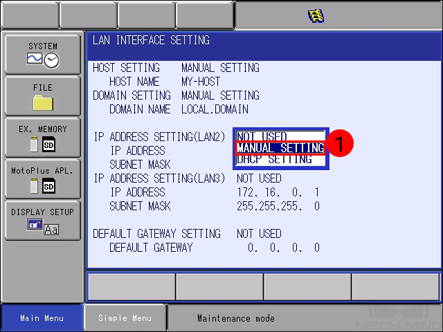
Select . At the OPTION FUNCTION interface, click LAN INTERFACE SETTING.
-
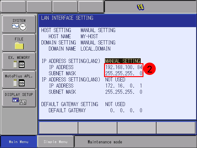
In the drop-down menu of IP ADDRESS SETTING(LAN2), select MANUAL SETTING, and set a proper IP ADDRESS and SUBNET MASK.
-
The IP address of LAN2 should belong to the same subnet as the IPC.
-
The subnet mask should be 255.255.255.0.
-
-
Press the
ENTERkey on the teach pendant, and a message saying *Modify? * will pop up. Click YES.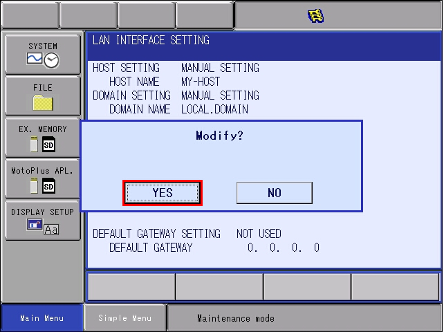
Set up “Robot and Interface Configuration” in Mech-Vision
-
Click Robot and Interface Configuration in the toolbar of Mech-Vision.
-
Select Listed robot from the Select robot drop-down menu, and then click Select robot model. Select the robot model that you use. Then click Next.
-
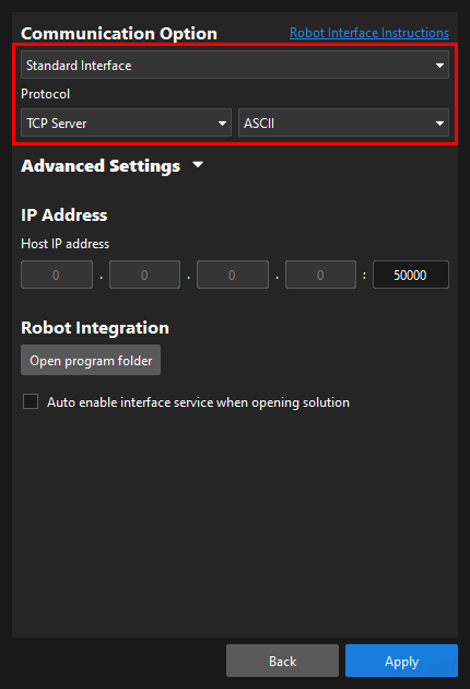
Select Standard Interface for Interface Type, and TCP Server and ASCII for Protocol. Then click Apply.
-
At the main interface of Mech-Vision, make sure the Interface Service in the toolbar is started.
Load the Program Files
| Before you start loading the program file to the robot, please perform file backup as needed. For detailed instructions, please refer to the operator’s manual of the YASKAWA controller. |
Prepare the Files
This section takes the YRC1000 robot as an example. Navigate to Mech-Center\Robot_Interface\YASKAWA from the installation directory of Mech-Mind Software Suite, and copy and paste the JBI folder and the mm_module_yrc1000.out file to the root directory of an empty formatted flash drive. The JBI folder is the foreground program, and the mm_module_yrc1000.out file is the background program.
|
Load the MotoPlus Application File to the Robot
-
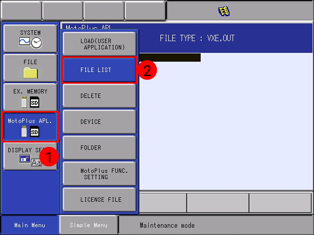
Under the Maintenance mode, select .
-
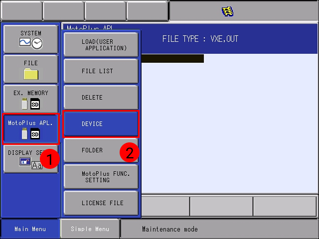
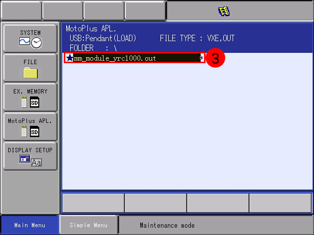
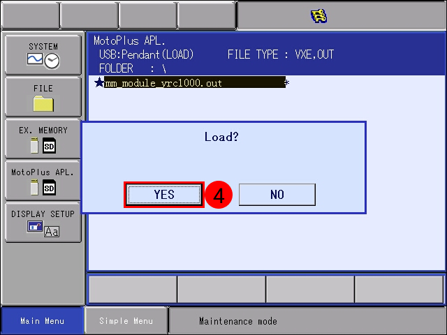
Select . Select mm_module_yrc1000.out, press the
ENTERkey, and click YES in the pop-up window to start loading the program.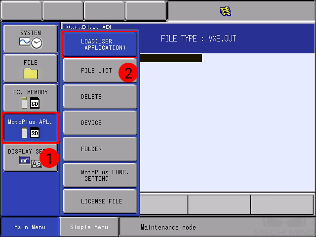
-
After the installation, select . You can see the installed file here.

Load the Job Files to the Robot
-
Restart the controller without pressing the MAIN MENU key, select , select MANAGEMENT MODE in the drop-down menu, and input the default password (sixteen 9s).
Press
Enterto enter the Maintenance mode.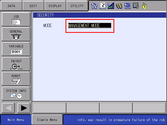
-
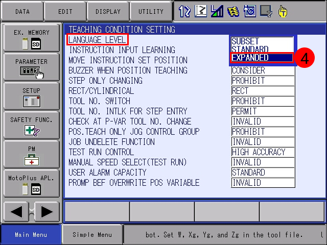
Press the right-arrow button
 in the lower-left. Then press , and select EXPANDED in the drop-down menu of LANGUAGE LEVEL.
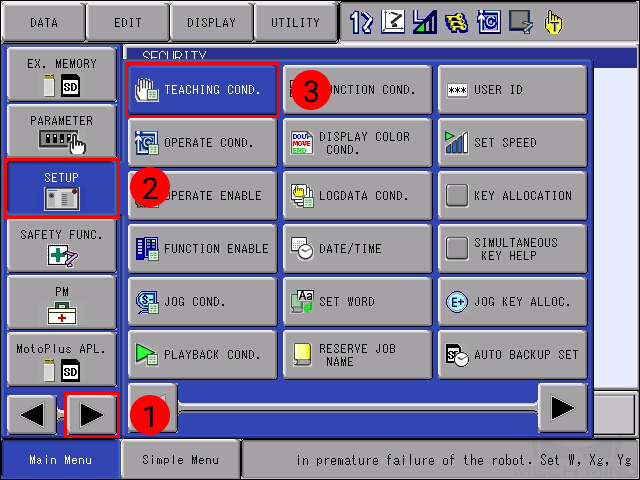
-
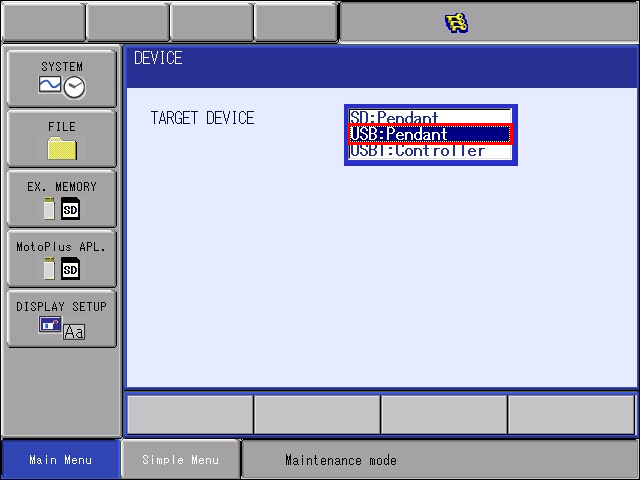
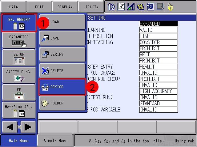
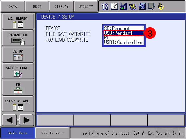
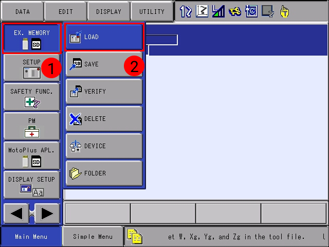
Select , and then select USB:Pendant for DEVICE.
-
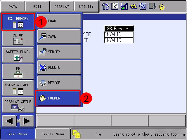
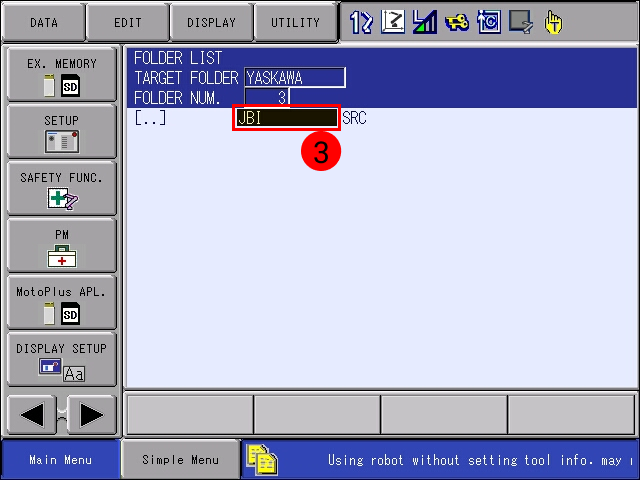
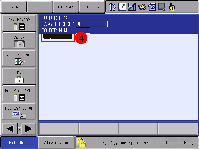
Click . In the FOLDER list, select and enter the JBI folder.
-
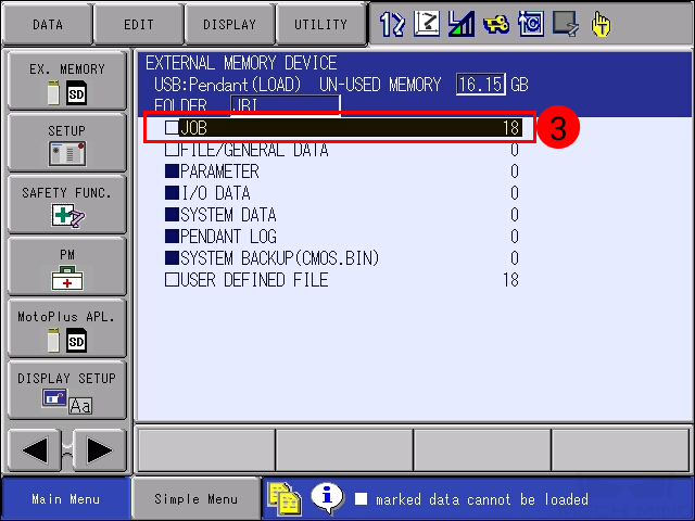
Select . Select JOB, and the programs to be loaded will be displayed.
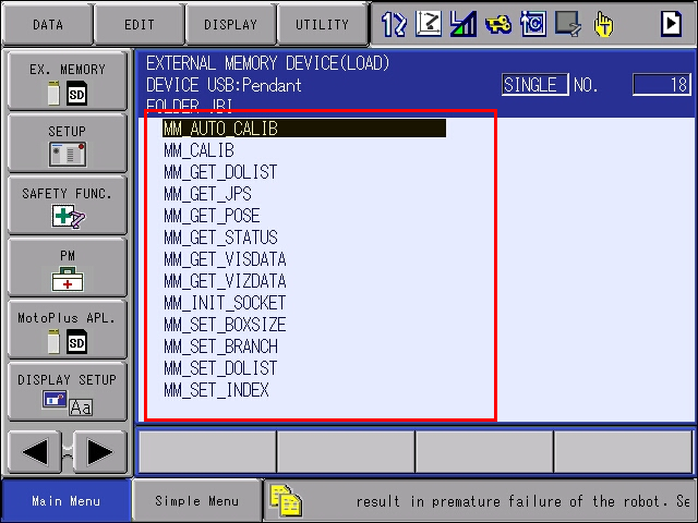
-
Select .
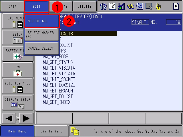

-
Press the
ENTERkey. Select YES in the pop-up message to start loading the programs.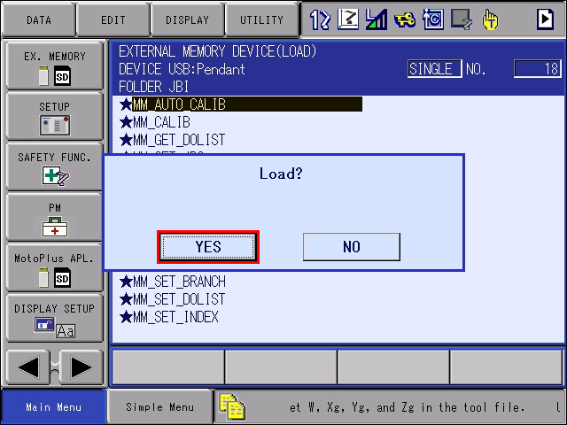
-
After loading completes, go to . You can see all the job files displayed.
Test Robot Connection
Test Connection
-
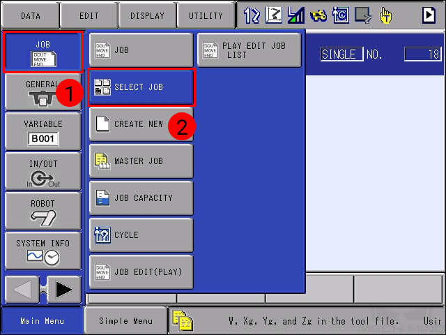
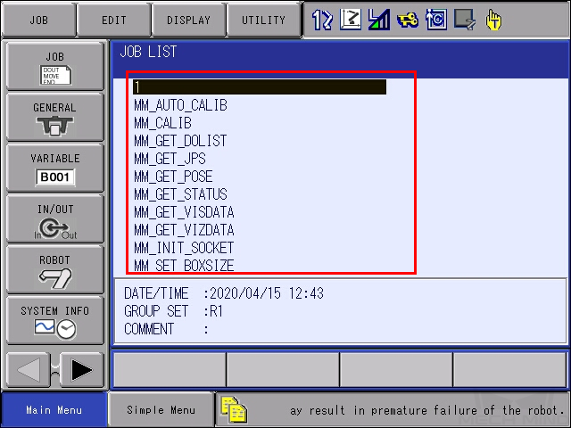
Select to enter the JOB LIST.
-
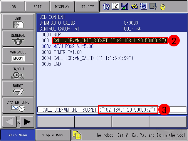
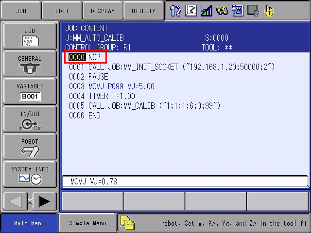
Select MM_AUTO_CALIB in the JOB LIST, and press the
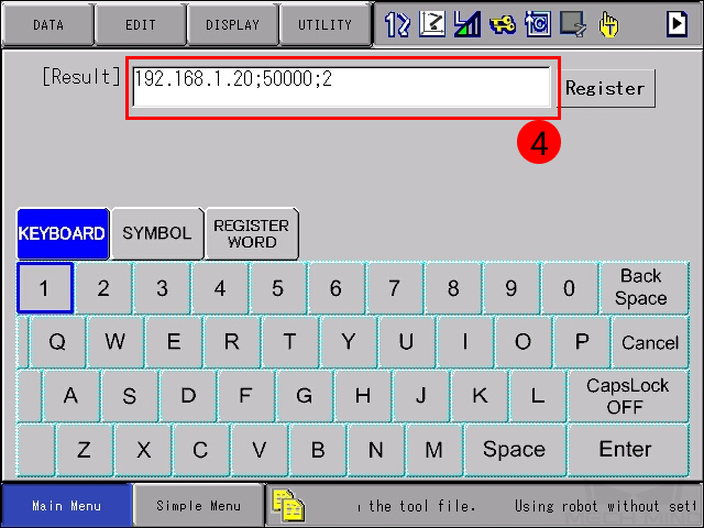
SELECTkey to open the job. Move the cursor to the instruction side of line 0001, press the SELECT key. In the text box at the bottom, move the cursor to the IP address and port number, and press theENTERkey. Change the IP address and port number to the actual ones of the IPC, and press Enter.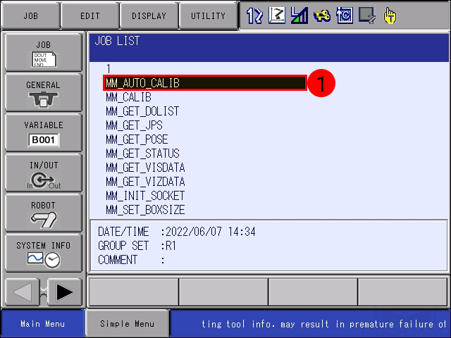
-
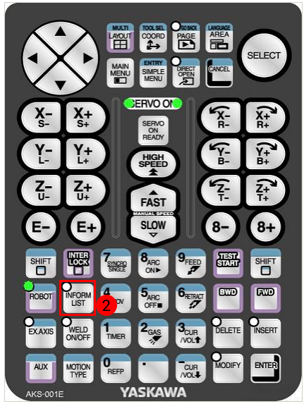
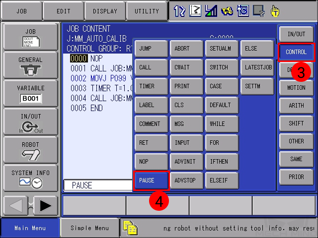
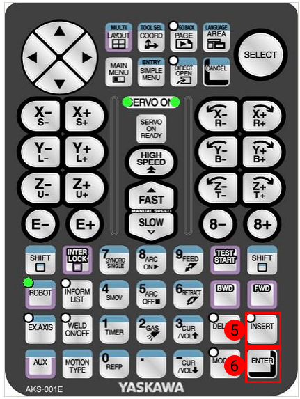
Keep the cursor on line 0001, and press the
INFORM LISTkey. Select in the pop-up menu on the right, and press on the teach pendant to insert a PAUSE command after line 0001.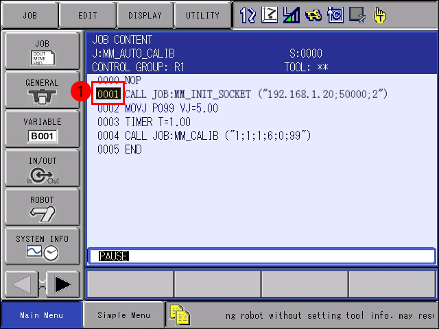

-
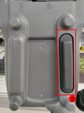
Turn to the TEACH mode, press the
SERVO ON READYkey, and then hold down theenable switchon the back while moving the cursor back to line 0000.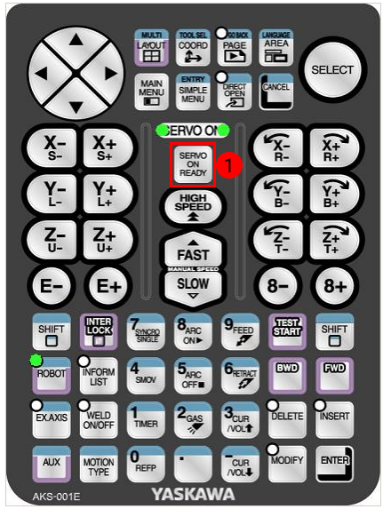
This step is to ensure that the job runs from the first line.
-
Press the
INTERLOCKkey andTEST STARTkey at the same time; the job will start running and should pause at line 0002 where the PAUSE command is.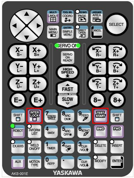
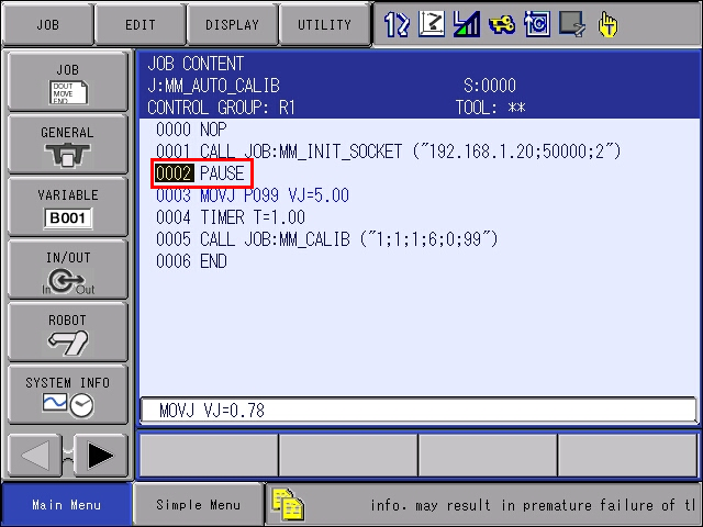
This step is a communication test. If the two sides can communicate, the program will automatically pause at the PAUSE command.
-
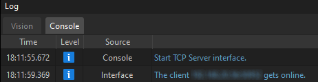
If the robot is connected successfully, the Console tab of Mech-Vision Log panel will display the corresponding log. Delete the PAUSE command after testing the communication to avoid mistaken pause during calibration.