Set up Standard Interface Communication with Kawasaki
This guide shows how to load the Standard Interface program files to a Kawasaki robot, and set up the Standard Interface communication between Mech-Mind Vision System and the robot.
| In this section, you will load the robot Standard Interface program and the configuration files to the robot system to establish the Standard Interface communication between the vision system and the robot. |
Preparation
Check Controller and Software Compatibility
-
Controller: E-series or F-series
-
Controller system software version: no requirement
-
Additional controller software options: no requirement
Set up the Network Connection
Connect the Hardware
Plug one end of the Ethernet cable into the network port of the IPC and the other end into the network port of the robot controller.
|
Set IP Addresses
-
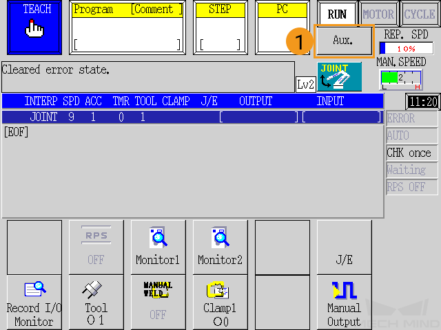
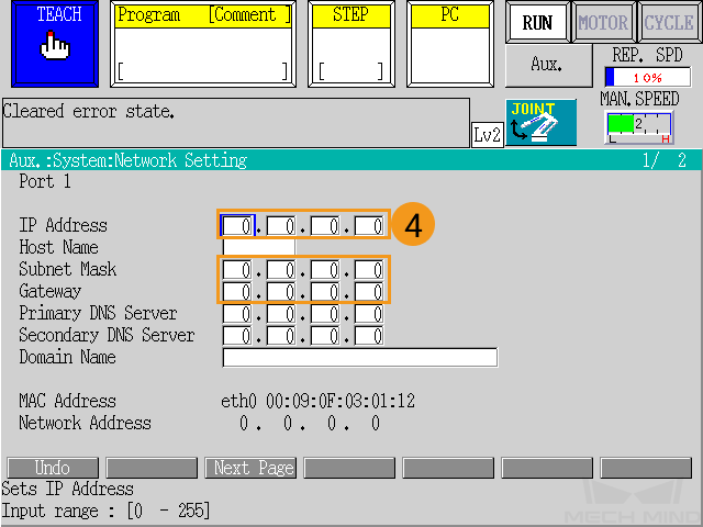
Press the Aux. button on the teach pendant, and then select to set the IP address of the robot Ethernet port.

-
Perform the corresponding operations based on the port to which the Ethernet cable is connected.
-
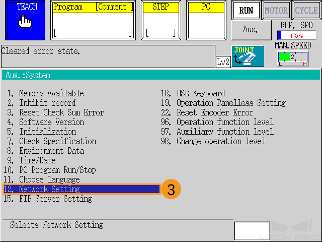
If the Ethernet cable is connected to port 1, configure the IP address and subnet mask for port 1 on the Network Setting page of port 1. The robot IP address must be in the same subnet as the IPC IP address. If a network gateway is used, set the Gateway parameter.
-
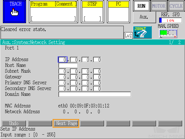
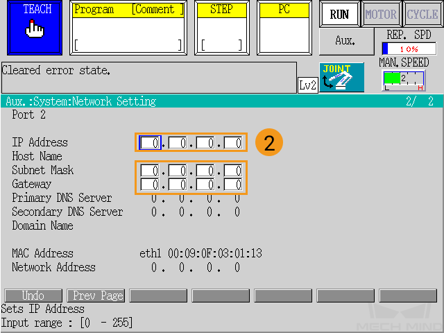
If the Ethernet cable is connected to port 2, click Next Page at the bottom of the Network Setting page of port 1 to go to the Network Setting page of port 2, and then configure the IP address and subnet mask for port 2. The robot IP address must be in the same subnet as the IPC IP address. If a network gateway is used, set the Gateway parameter.
-
-
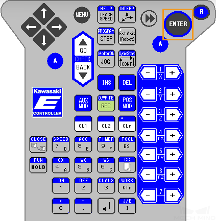
After you set the IP address, press the ENTER key on the teach pendant to confirm.
-
Restart the controller.
-
In the IPC, set the IP address of the IPC.
To allow communication between the IPC and the robot controller, the IP addresses of the IPC and robot controller must reside in the same subnet. This means that the network portions and subnet masks of the IP addresses should be the same. For example, 192.168.100.169/255.255.255.0 and 192.168.100.170/255.255.255.0 are in the same subnet.
Set up Communication with Robot
-
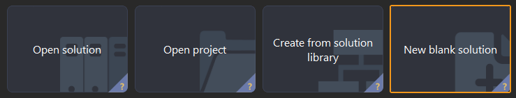
Open Mech-Vision. You may enter different interfaces. Create a new solution according to the instructions below.
-
If you have entered the Welcome interface, click New blank solution.
-
If you have entered the main interface, click on the menu bar.
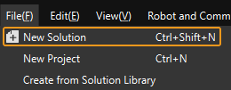
-
-
Click Robot Communication Configuration on the toolbar of Mech-Vision.
-
In the Robot Communication Configuration window, complete the following configurations.
-
Click the Select robot drop-down menu, and select Listed robot. Click Select robot model, and select the robot model that you use. Then, click Next.
-
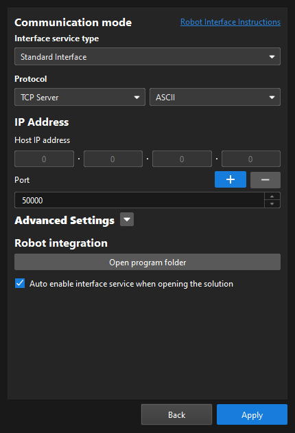
In the Communication mode section, select Standard Interface for Interface service type, TCP Server for Protocol, and ASCII for the protocol format.
-
It is recommended to set the port number to 50000 or above. Ensure that the port number is not occupied by another program.
-
Under Robot integration, click Open program folder.
-
If you want to manually load program files, you must perform this step. Otherwise, skip this step.
-
The files needed for subsequent loading will be copied from this folder. Do not close this folder.
-
-
(Optional) Select Auto enable interface service when opening the solution.
-
Click Apply.
-
-
On the main interface of Mech-Vision, make sure that the Robot Communication Configuration switch on the toolbar is flipped and has turned blue.

Load the Program Files to the Robot (Auto)
You can follow the instructions below to allow standard interface programs or standard interface example programs to be auto-loaded to the robot. In this example, standard interface programs are auto-loaded by performing the following steps. The steps to auto-load standard interface example programs are similar.
| If the auto-load process fails and you cannot resolve the issue, proceed to Load the Program Files to the Robot (Manual). |
-
Navigate to the installation directory of Mech-Vision and Mech-Viz, go to the Robot Program Loader folder by using the
Communication Component\tool\Robot Program Loaderpath, and then double-click the Robot Program Loader program to open the loader. The main interface of the loader appears.To switch languages in the loader, select a different language from the drop-down list in the upper-right corner and restart the loader for the new language to take effect. -
In the main interface, select the KAWASAKI robot brand, enter the actual robot IP address, and then click Connect.
If the connection fails, click Test network connection in the lower-right corner to troubleshoot the issue. 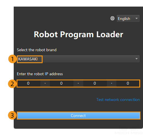
-
In the KAWASAKI Program Loading interface, click the folder icon, select the path of the backup files, and then click Back up. If the files are backed up, a message that indicates the backup is successful is displayed in the Log section.
If errors occur in the subsequent loading process, the files can be used to reset the robot system. 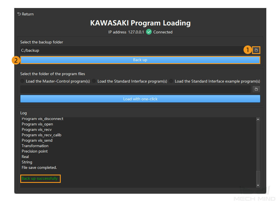
-
Select Load the master-control program(s) and then click Load with one-click. If the files are loaded to the robot, a message that indicates the program files are successfully loaded appears in the Log section.
If you want to load standard interface example programs, select Load the standard interface example program(s) and then click Load with one-click. 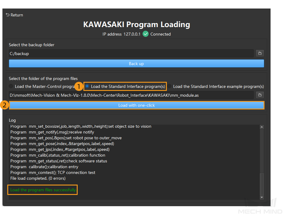
After the preceding operations are complete, proceed to Test Standard Interface Communication.
Load the Program Files to the Robot (Manual)
| If you have completed operations in Load the Program Files to the Robot (Auto), skip this section. |
Prepare the Files
-
Plug the flash drive into the USB port of the IPC.
-
On the IPC, copy the mm_module.as file from the opened program folder (the
KAWASAKIfolder) to the root directory of the flash drive, and then unplug the flash drive.You can also find the program folder in the
Communication Component/Robot_Interface/KAWASAKIpath in the installation directory of Mech-Vision and Mech-Viz.
Precautions for Loading Files
-
Save user programs.
If user programs exist in the program list on the teach pendant, save them before you load program files. If no user programs exist on the teach pendant, skip this step. Click here for instructions
-
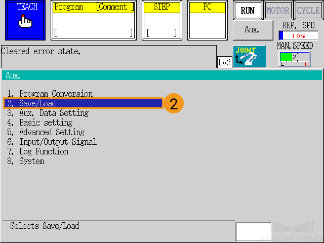
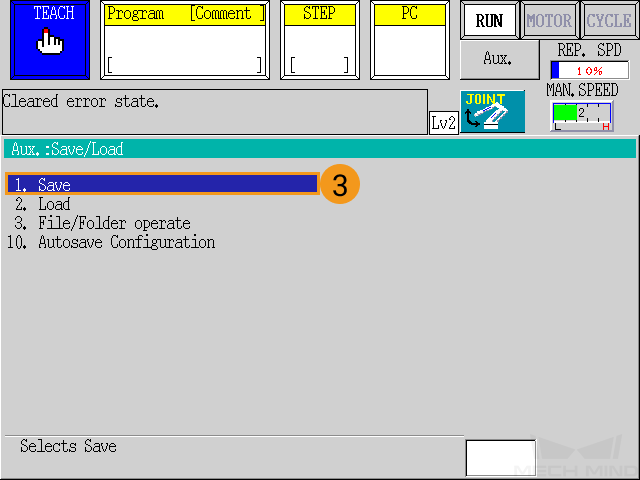
Press the Aux. button, and select .

-
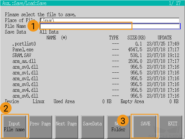
On the Save page, press Input File name to enter the file name, and then press the Save button. After the file is saved, press the R key on the teach pendant to return to the main page.
-
-
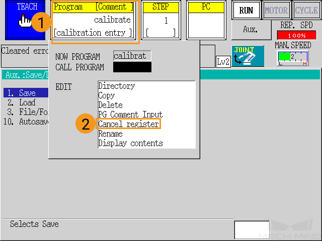
Before you load files, check if registered programs exist in the Program area on the teach pendant. If yes, deregister these programs by following the instructions as shown below.
-
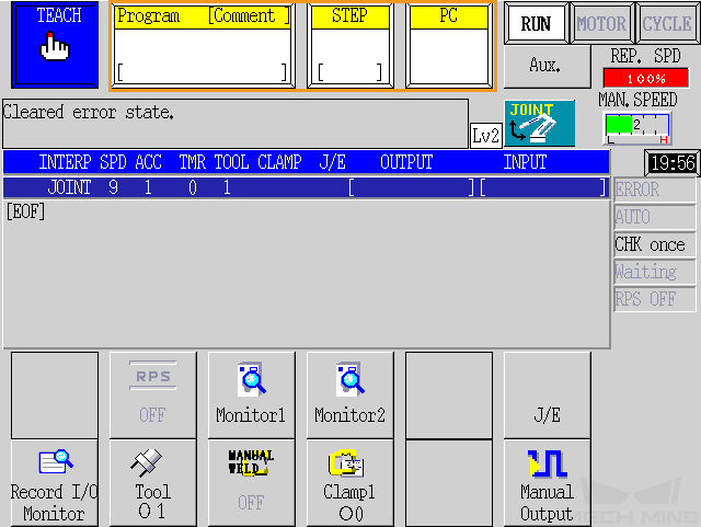
Before you load files, check to make sure that the robot is in teach mode. After the above checks, the interface of the teach pendant is shown below.
Load the Program Files to the Robot
-
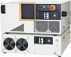
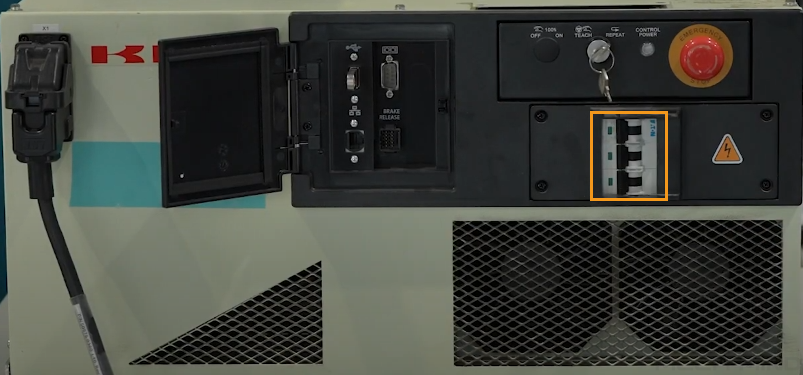
Plug the flash drive into the USB port on the controller panel.
-
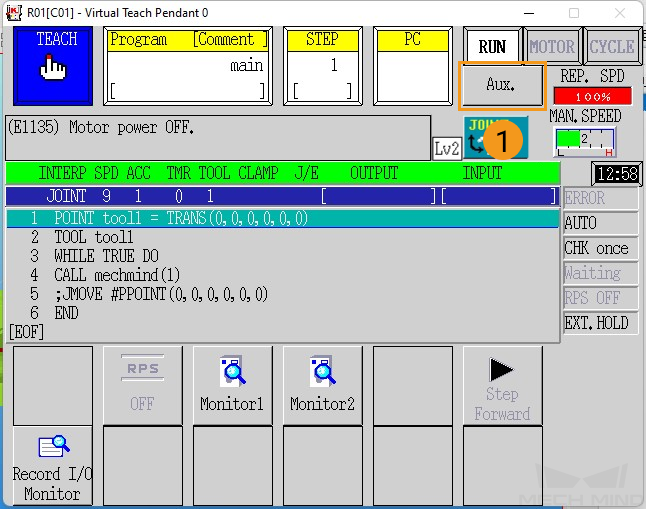
Press the Aux. button on the teach pendant.
-
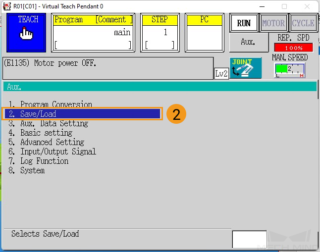
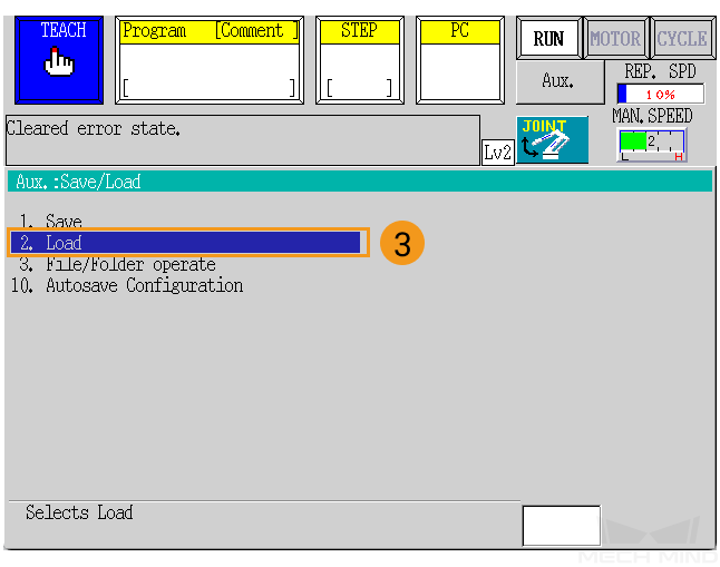
Select .
-
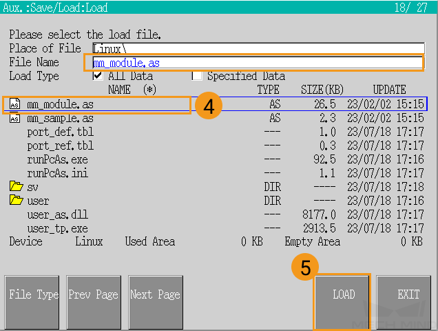
Double-click the program file mm_module.as to allow mm_module.as to be displayed in the File Name field. Then, select LOAD.
-
After you load the files, check to make sure that no errors occurred during the loading process. Press the R key on the teach pendant to exit.

Test Standard Interface Communication
Select and Modify the Program Used for the Communication Test
-
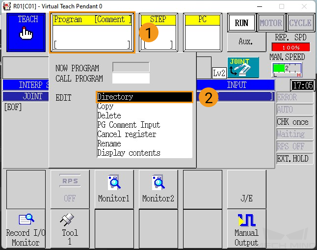
Select the program area in the teach mode. Select Directory in the pop-up menu.
-
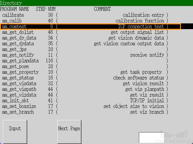
Select the foreground program mm_comtest in the Directory list. Then, press the ENTER key on the teach pendant to confirm the selection.
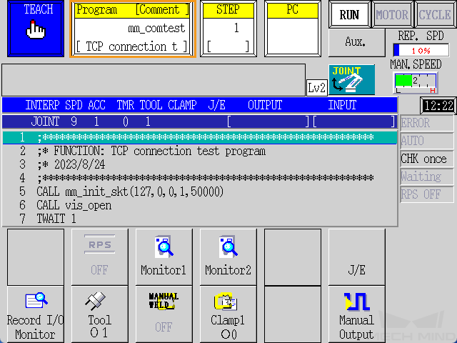
The following figure shows the interface after the program is added.
-
Reset the parameters of the mm_init_skt function in the mm_comtest program by performing the following steps.
-
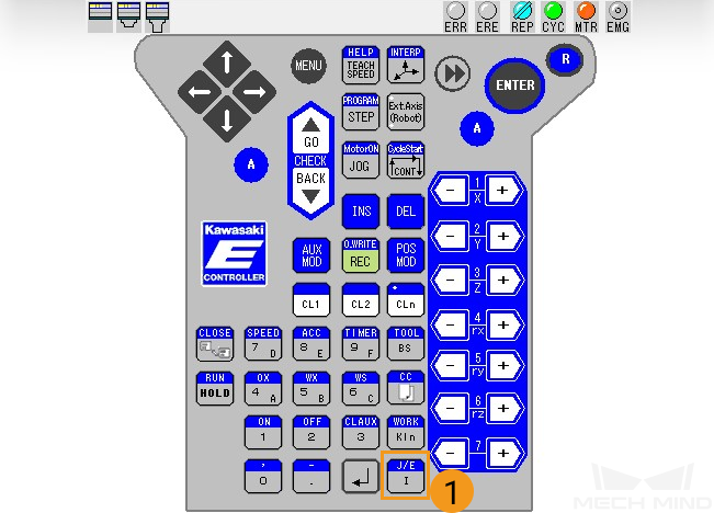
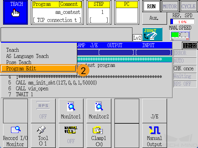
Press J/E on the teach pendant, select Program Edit in the pop-up menu, and then press ENTER to confirm.
-
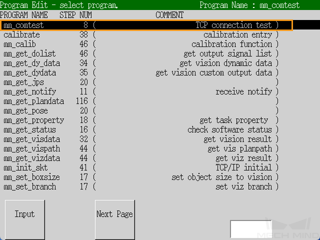
Select mm_comtest in the program menu and press the ENTER key to confirm.
-
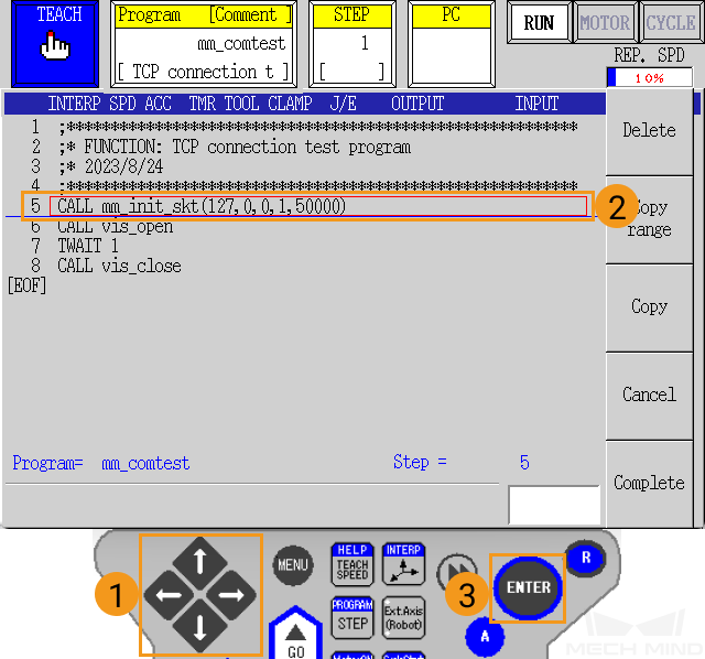
Move the red selection frame to the line that contains mm_init_skt on the teach pendant by using the arrow keys to select call mm_init_skt(127,0,0,1,50000). Then, press the ENTER key to confirm.
-
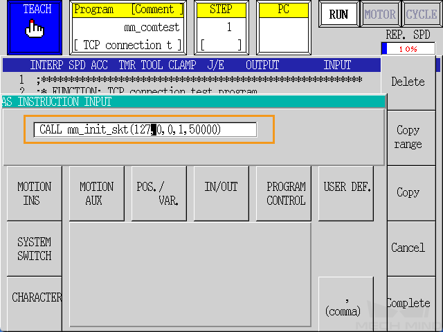
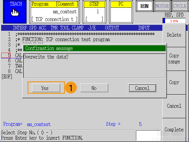
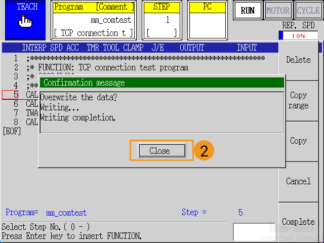
Use the arrow keys and number keys on the teach pendant to change 127,0,0,1 to the IP address of the IPC and “50000” to the host port number set in Mech-Vision. After you modify the settings, press ENTER to confirm and press R to exit.
-
In the prompted confirm window, press Yes and then Close.
-
Run the Program and Test Connection
-
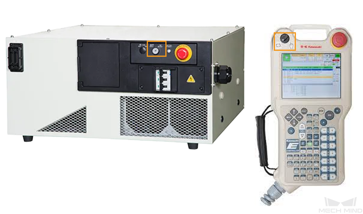
Switch Teach/Repeat on the controller to REPEAT and switch the teach lock on the teach pendant to OFF. After these operations, the robot should be in REPEAT mode.
-
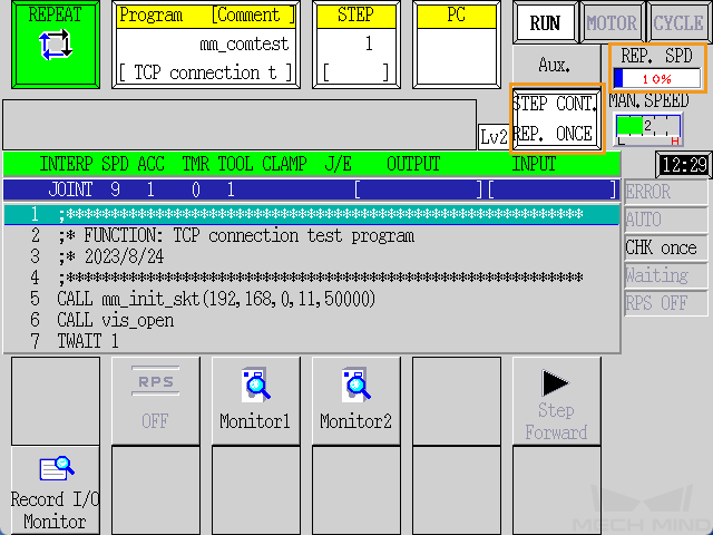
Switch to the STEP CONT. REP. ONCE mode on the screen, and reset REP. SPD to 10%.
-
Hold the A key on the keypad and press MOTOR on the screen to make MOTOR lit. Hold A on the keypad and press CYCLE on the screen to make CYCLE lit. If RUN does not turn green, hold the A key and press the RUN/HOLD key on the teach pendant.
When RUN, MOTOR, CYCLE are all lit, the communication test program starts to run. 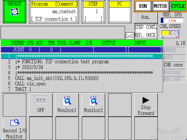
-
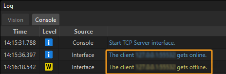
If the communication between the robot and the vision system is set up, a log will be recorded on the Console tab of the Log panel of Mech-Vision.