Master-Control Communication Setup
This guide shows you how to set up Master-Control communication with a FANUC robot.
Preparation
Check Controller and Software Versions
|
The models and versions listed below are tested and can be used. For other models and versions, you may refer to this guide for operation. If any issues occur, please contact Mech-Mind Technical Support. |
-
Controller system version: V7.5, V7.7, V8.x, V9.x, and V10.1
Click here for instructions
-
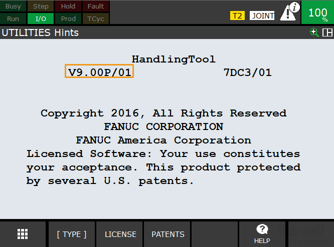
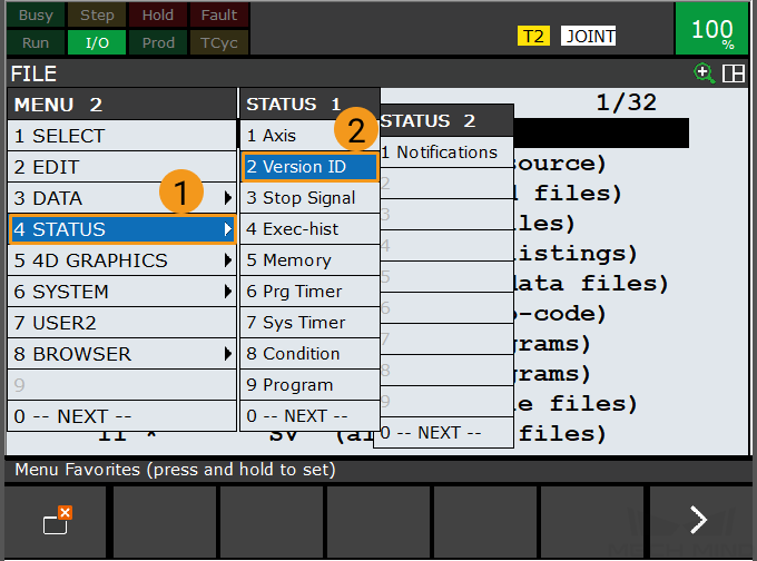
Press the MENU key on the teach pendant, select by using the arrow keys, and then press ENTER.
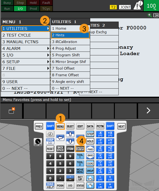
-
In the “UTILITIES Hints” interface, the selected area in the image is the system version of the robot controller.
-
-
Ensure that the required additional controller software packages are installed:
-
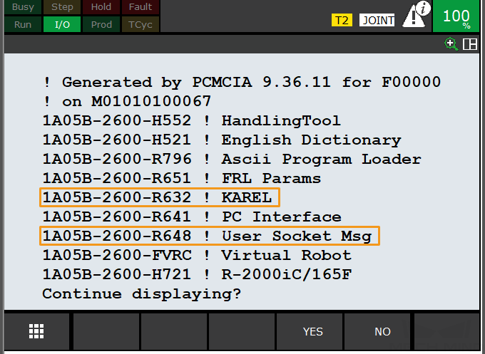
R651 or R632 (KAREL) MUST be installed.
-
R648 (User Socket Msg) MUST be installed.
Click here for instructions
-
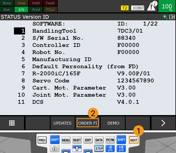
Press the MENU key on the teach pendant. Select NEXT using the arrow keys, and then press ENTER.
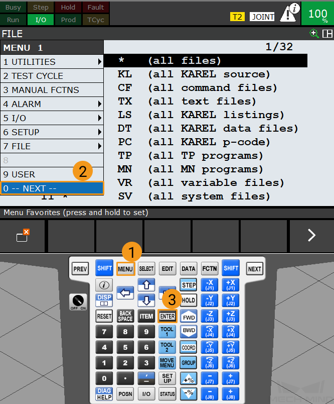
-
Select using the arrow keys, and then press ENTER.
-
Press NEXT, and then press F3 (i.e., select ORDER FI).
-
Ensure the required software packages are installed as shown in the image below.
-
Set up the Network Connection
Connect the Hardware
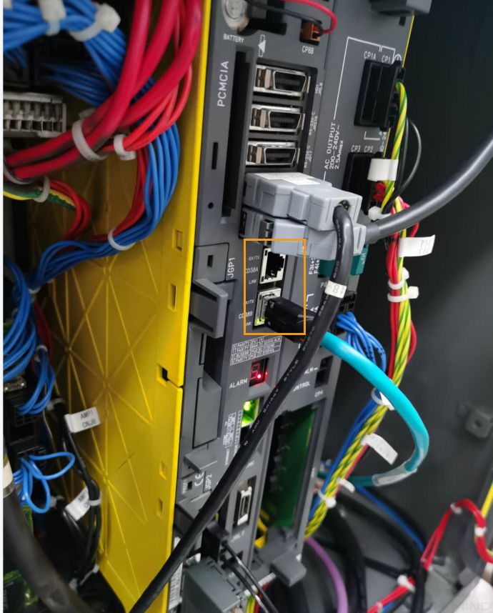
Plug the Ethernet cable of the IPC into the Ethernet port of robot controller as shown in the figure. You can plug the cable into either the CD38A port or CD38B port. CD38A corresponds to Port#1 in the robot IP setting, while CD38B corresponds to Port#2.
Set the IP Address
-
Press MENU on the teach pendant. Select using the arrow keys. Press ENTER to open the SETUP Protocols window.

-
Select TCP/IP and press F3 (i.e., select DETAIL) to open the SETUP Host Comm window.

-
Perform the corresponding operations based on the port to which the Ethernet cable is connected.
If both Port 1 and Port 2 are enabled, their IP addresses must be on different subnets. -
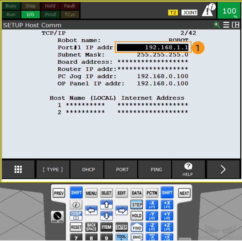
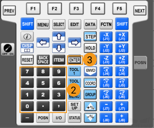
If the Ethernet cable is connected to CD38A port (Port#1), modify the robot’s IP address as follows: select the IP address line using the arrow keys, press the ENTER key, input the robot’s IP address using the keyboard of the teach pendant, and then press ENTER. Please note that the robot IP address should be on the same subnet as that of the IPC, and the two IP addresses should be different.
-
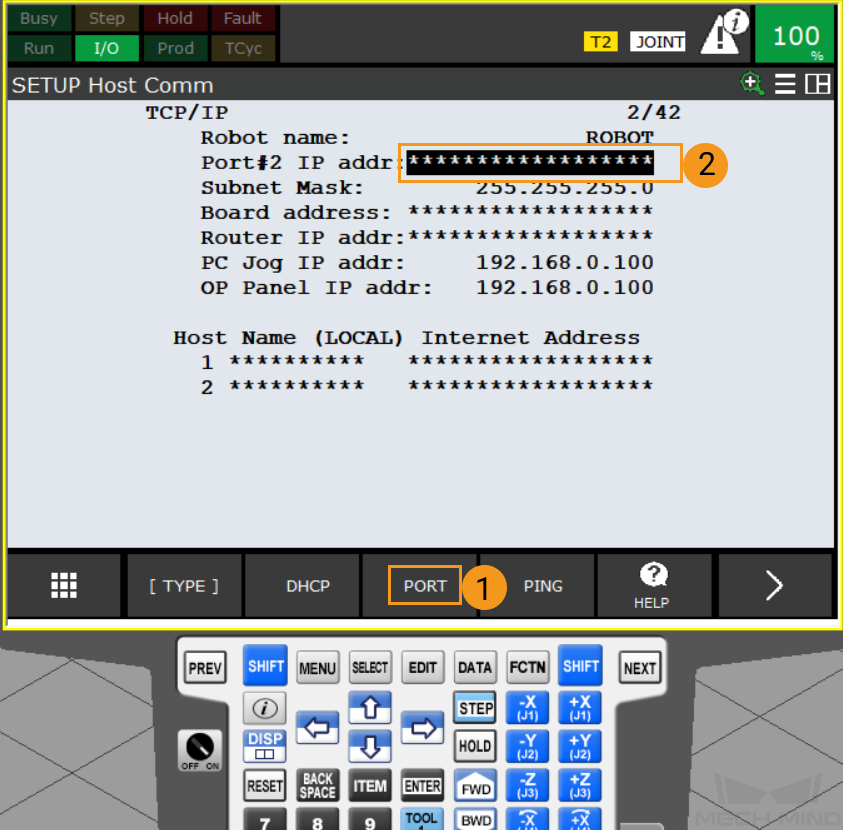
If the Ethernet cable is connected to CD38B port (Port#2), modify the robot’s IP address as follows: Press F3 (i.e., select PORT) to switch to Port#2. Select the IP address line using the arrow keys, press the ENTER key, input the robot’s IP address using the keyboard of the teach pendant, and then press ENTER. Please note that the robot IP address should be on the same subnet as that of the IPC, and the two IP addresses should be different.
-
Load the Program Files to the Robot
Back up Robot Program Files
-
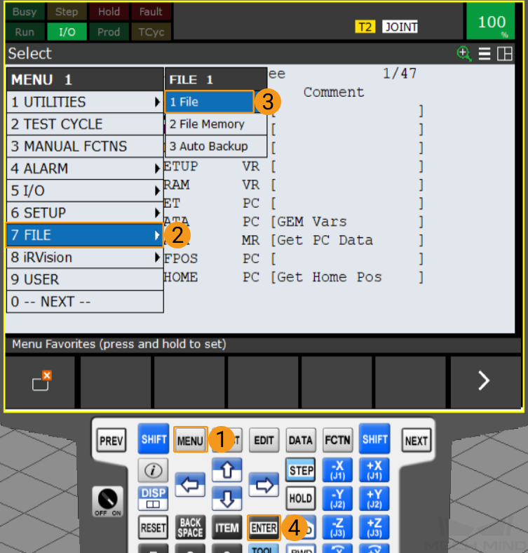
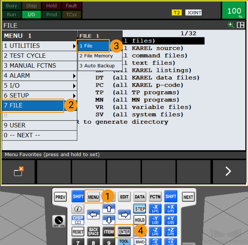
Plug the USB flash disk, and press MENU. Select using the arrow keys. Then, press ENTER to open the FILE window.
-
Please ensure that your flash drive is no more than 32 GB in size and the file system of the flash drive is FAT32.
-
You can connect the flash drive to the robot controller or the teach pendant according to the actual requirement.
-
-
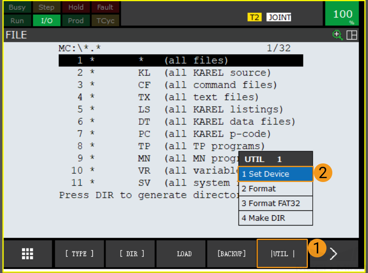
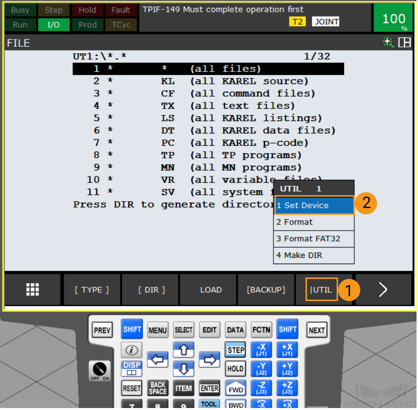
In the FILE window, press F5 (i.e., select UTIL). Select Set Device using the arrow keys, and press ENTER to open the USB folder.
-
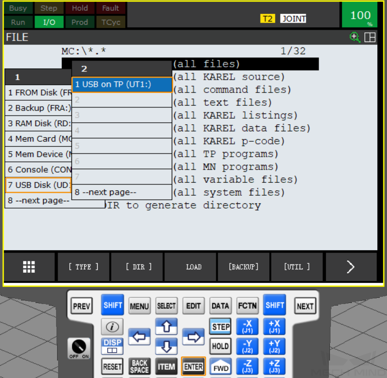
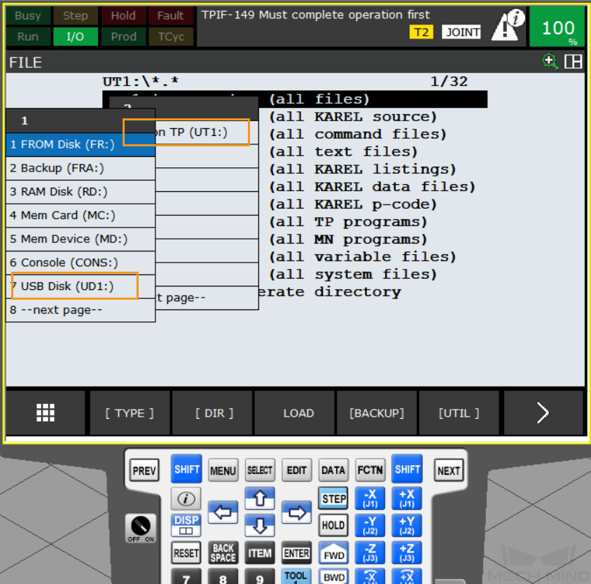
If your flash drive is connected to the controller, select USB Disk (UD1:) using the arrow keys, and press ENTER. If your USB flash drive is connected to the teach pendant, select USB on TP (UT1:) using the arrow keys, and press ENTER.
-
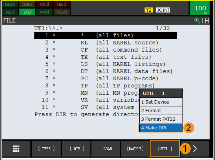
In the USB FILE window, press F5 (i.e., select UTIL). Select Make DIR, and then press ENTER.
-
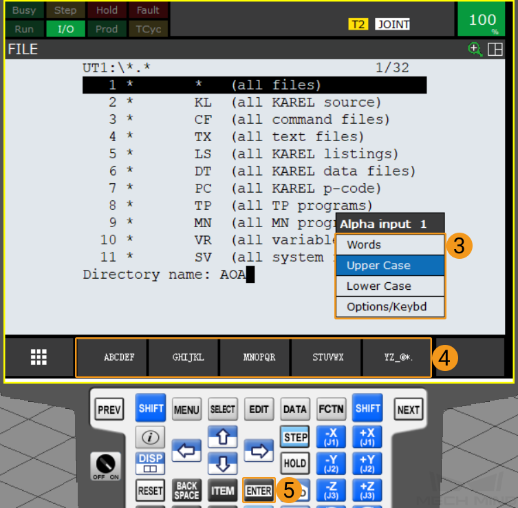
Select Words, Upper Case, Lower Case, or Options/Keybd and use the keys F1~F5 to name the folder, for example, as AOA. Then press ENTER to confirm and enter the new folder.
-
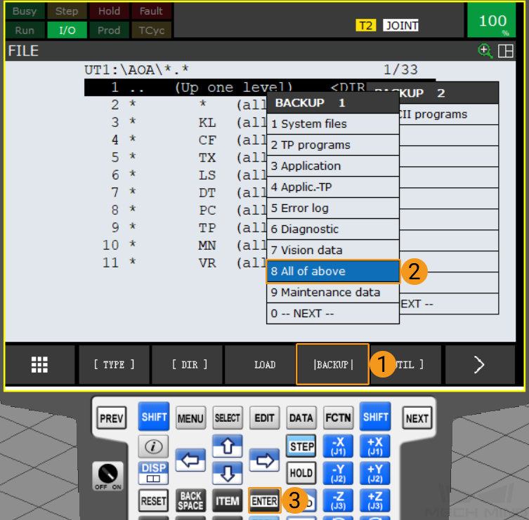
Press F4 (i.e., select BACKUP). Select All of above with the arrow keys, and press ENTER to backup the files.
-
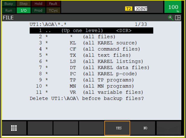
A message asking whether to delete the new folder after backing up the files will be displayed on the screen. Press F4 to select YES. Then a message asking whether to back up all files will be displayed on the screen. Press F4 to select YES.

-
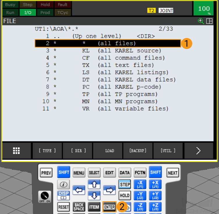
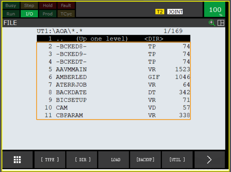
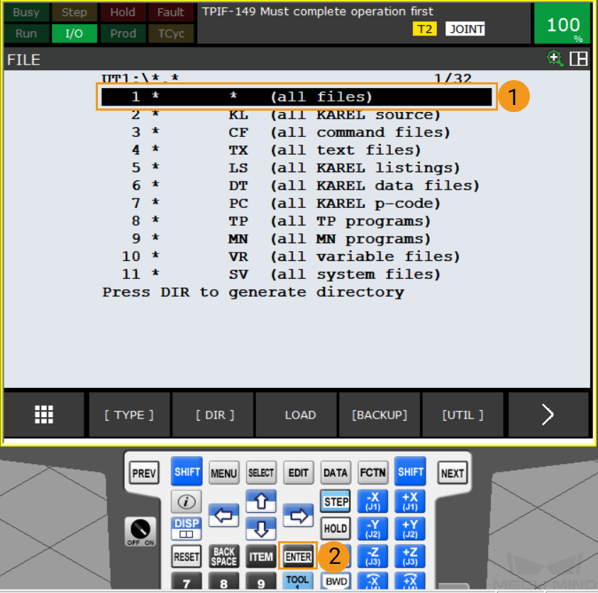
After the backup is complete, select all files using the arrow keys, and then press ENTER to view all backup files.
Prepare Program Files
Navigate to Communication Component/Robot_Server/Robot_FullControl/fanuc from the installation directory of Mech-Vision & Mech-Viz, and copy all files and folders within this folder and paste them to the root directory of the flash drive.
|
Load the Files to the Robot
-
Plug the USB flash disk, and press MENU. Select using the arrow keys. Then, press ENTER to open the FILE window.
You can connect the flash drive to the robot controller or the teach pendant according to the actual requirement.
-
Press F5 (i.e., select UTIL). Select Set Device using the arrow keys, and press ENTER to open the USB folder.
-
If your flash drive is connected to the controller, select USB Disk (UD1:) using the arrow keys, and press ENTER. If your USB flash drive is connected to the teach pendant, select USB on TP (UT1:) using the arrow keys, and press ENTER.
-
Select all files using the arrow keys, and press ENTER to access the root directory of the USB flash drive.
-
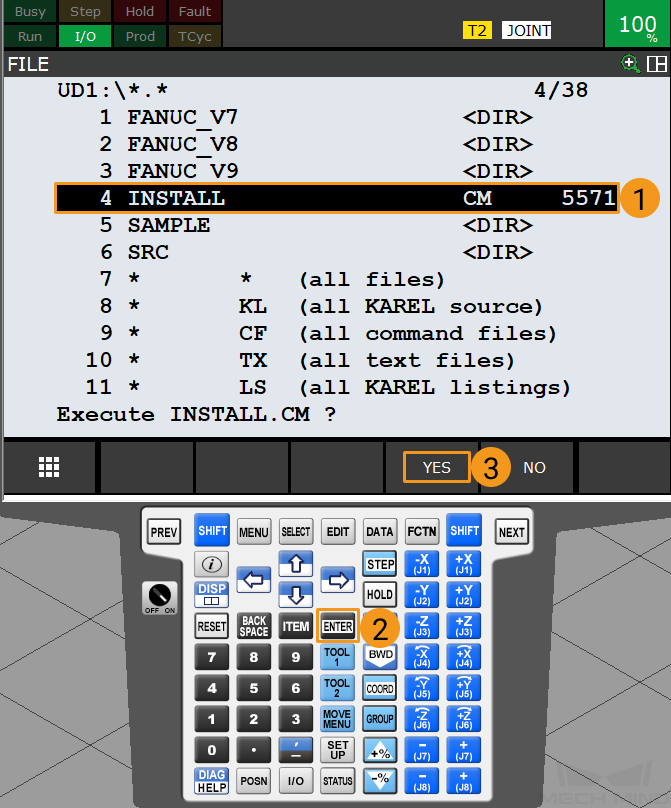
In the root directory of the USB flash drive, select INSTALL using the arrow keys. Press ENTER, and press F4 (i.e., select YES) to start loading the programs.
-
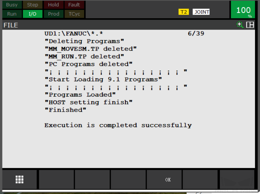
When the message “Programs Loaded” is displayed, the program files have been loaded successfully. Press F4 (i.e., select OK) to return to the previous interface.
-
Restart the Robot.
Test Master-Control Communication
Run the Program
-
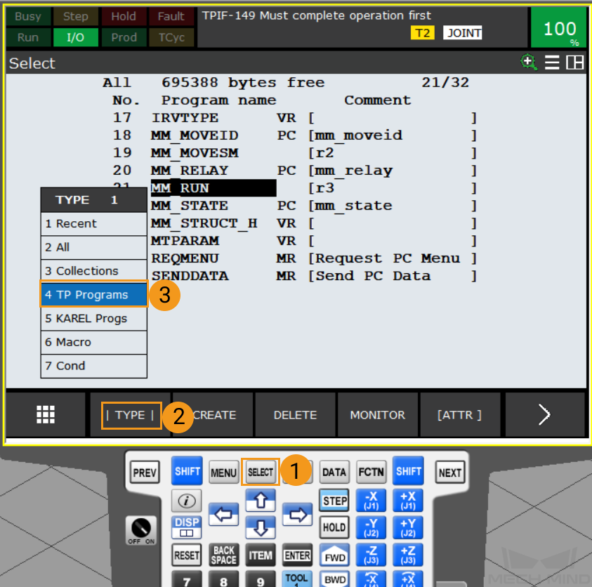
Press the SELECT key on the teach pendant to open the program selection window, and then press F1 (i.e., select TYPE). Select TP Programs using the arrow keys and then press ENTER.
-
Select MM_RUN using the arrow keys, and then press ENTER.

-
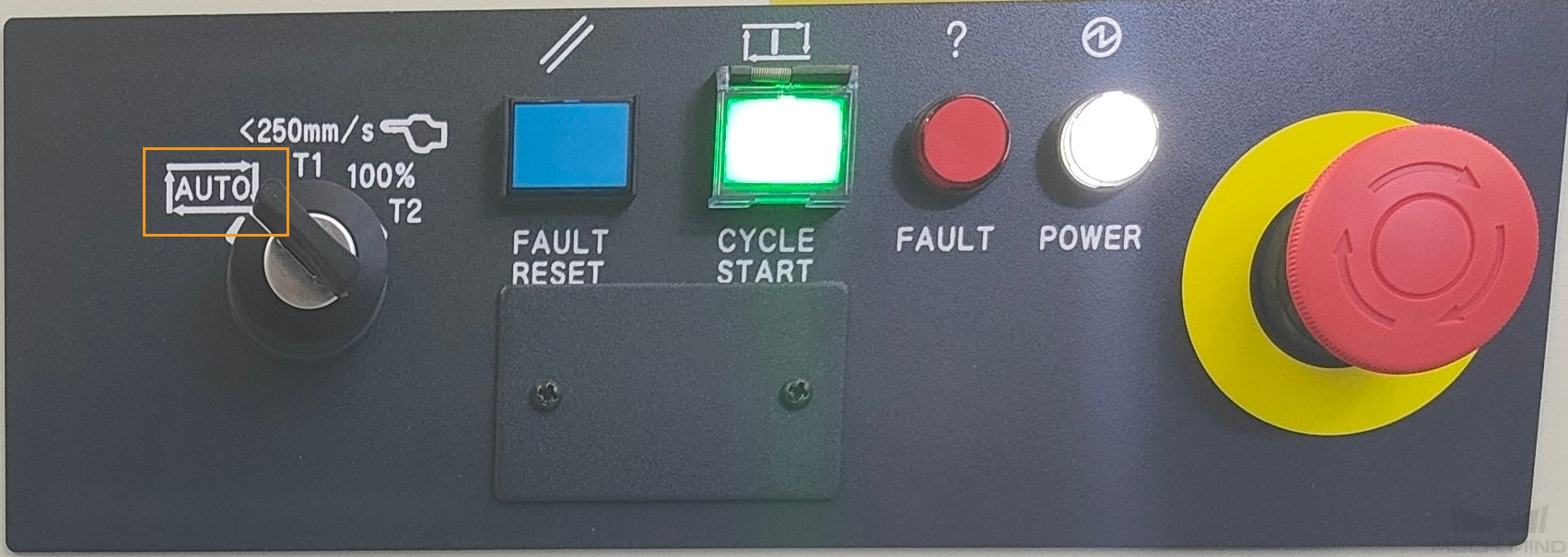
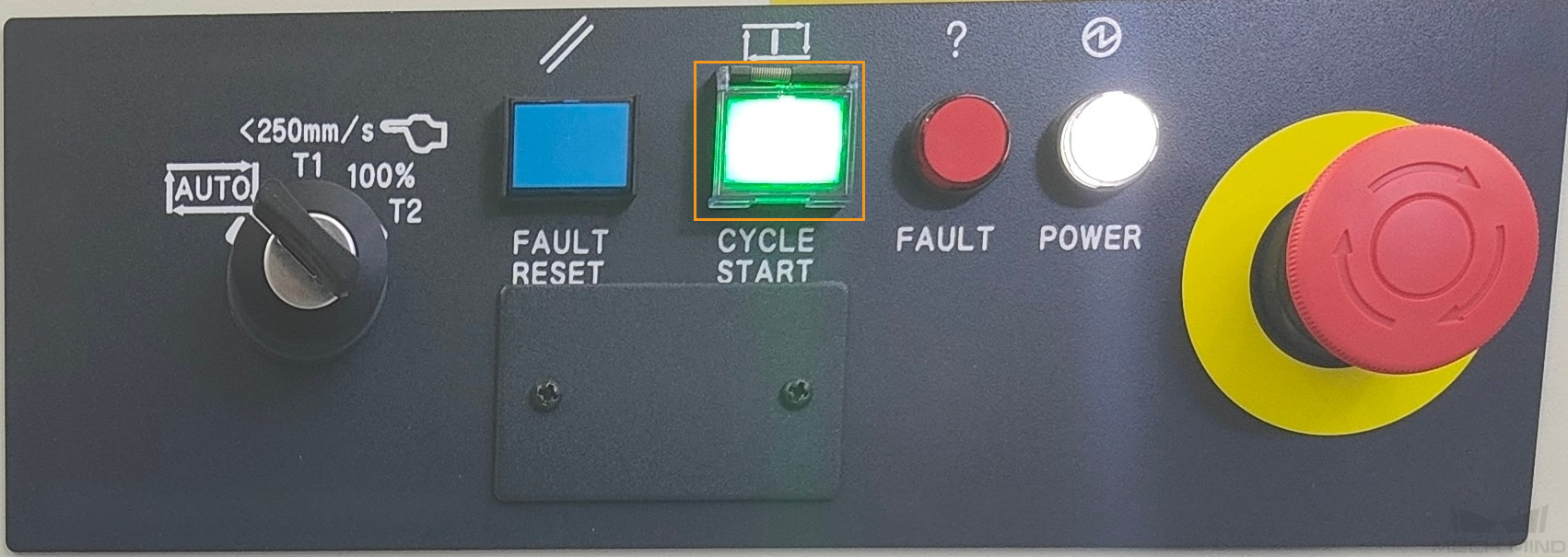
Turn the key switch on the controller to AUTO.
-
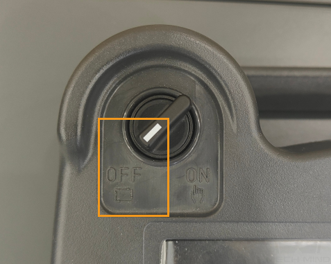
Turn the switch on the teach pendant to OFF.
-
Press the CYCLE START button on the controller to run the program automatically.
-
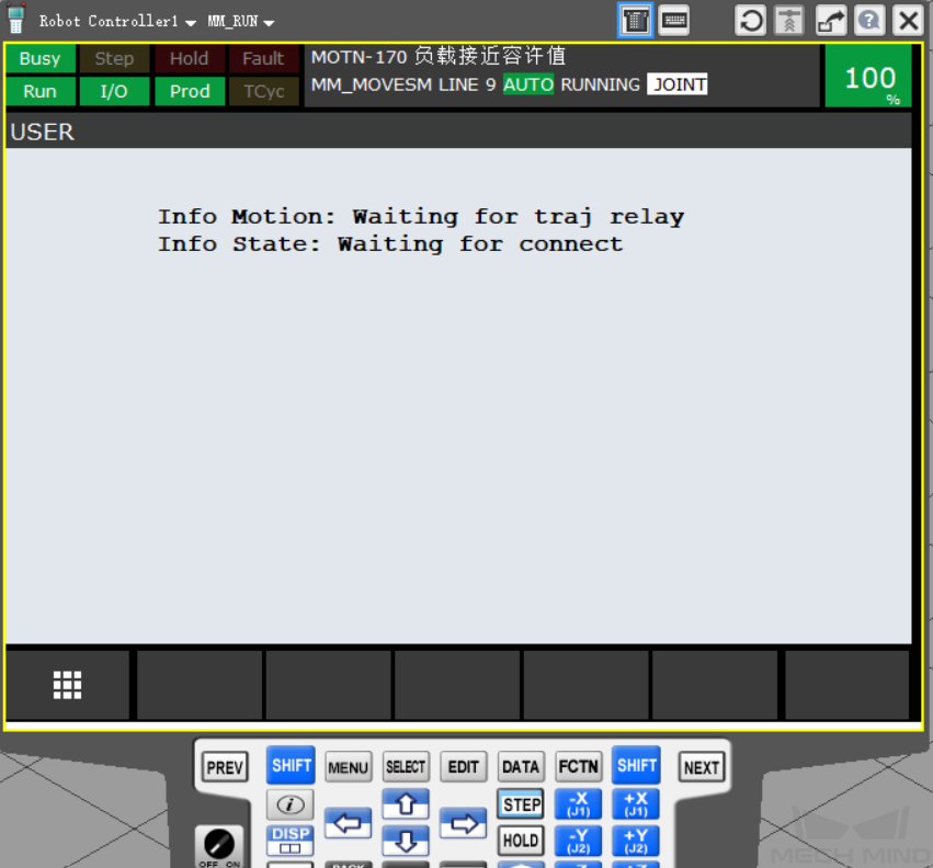
When Info State: Waiting for connect is displayed in the teach pendant interface, the program has been successfully executed.
Create a Mech-Viz Project
-
Open Mech-Viz, press Ctrl + N on the keyboard to create a new project. Select the robot model corresponding to your real robot brand and model on the interface as shown below.

-
Press Ctrl + S and create or select a folder to save the project.
-
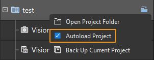
Right-click the project name in the left panel in Mech-Viz and select Autoload Project.
Connect to the Robot
-
Click Master-Control Robot on the toolbar of Mech-Viz.
-
Input the IP address of the real robot in Robot IP address (the IP address in the picture is only an example). Click Connect the robot.

If Mech-Viz successfully connects the real robot, the current status will change to Connected. Meanwhile, the icon in the toolbar will turn from blue to green.
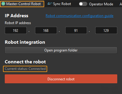
If the connection fails, please double-check the robot IP address.
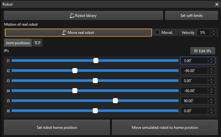
Move the Robot
-
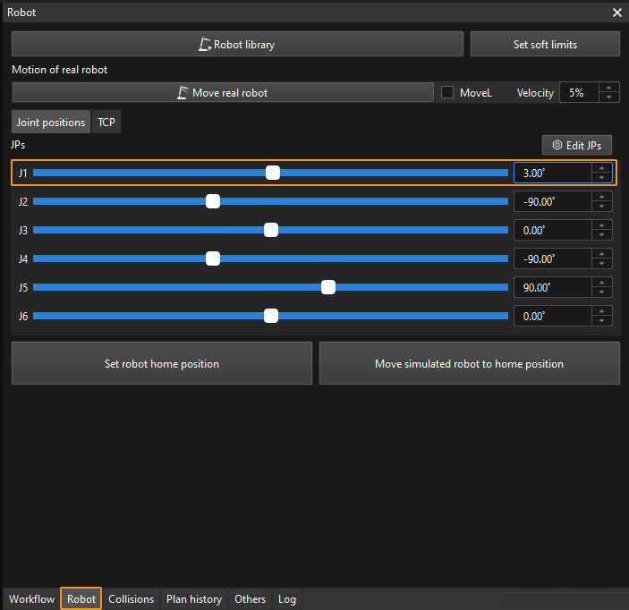
In the toolbar of Mech-Viz, change the “Vel.” (velocity) and “Acc.” (acceleration) parameters to 5%.

-
Click Sync Robot in the toolbar, and you can synchronize the poses of the simulated robot in the 3D simulation space with the poses of the real robot. Then click Sync Robot again to unselect it.

-
In the Robot tab, slightly adjust the value of “J1”, for example, from 0˚ to 3˚. This operation will move the simulated robot.
-
Click Move real robot and check if the real robot has moved. If the real robot has reached the JPs set for the simulated robot, the master-control communication is working.
When moving the robot, please ensure the safety of personnel. In the case of an emergency, press the emergency stop button on the teach pendant!