DENSO Standard Interface Commands
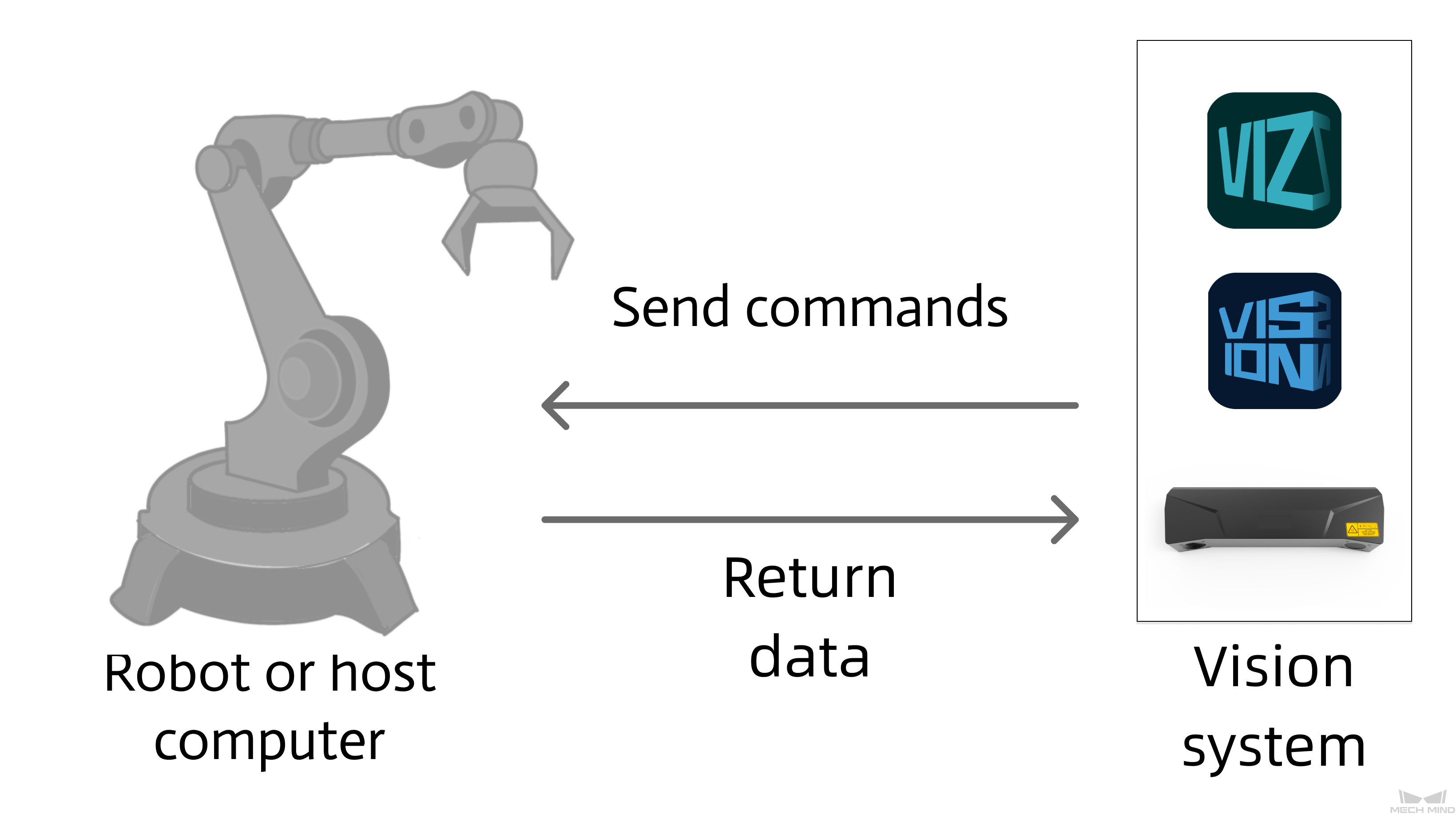
This section describes standard interface commands used in TCP communications between a DENSO robot and Mech-Mind Vision System. The robot (the client) sends commands to Mech-Mind Vision System (the server), and Mech-Mind Vision System returns the processed data to the robot.
Command Overview
Precautions
-
Unit of data:
-
The unit of joint positions is degree (°).
-
The robot flange pose or robot tool pose is represented in six dimensions, denoted as [x, y, z, a, b, c].
-
The position components x, y, and z in the pose are measured in millimeters (mm).
-
The orientation components a, b, and c in the pose are represented as Euler angles, with units in degrees (°).
-
The format of the Euler angles for the input flange pose corresponds to the selected robot brand. If another robot brand is selected in the communication configuration, the corresponding Euler angle convention must be chosen.
-
-
Vision point and waypoint:
-
Vision point: An object recognized by Mech-Vision. A vision point has information including the object pose, label, dimensions, and custom data.
-
Waypoint: Each point that the robot reaches when moving along the planned path. A waypoint has information including the robot pose, label, and motion type. Waypoints can be divided into two categories:
-
Vision Move waypoint: Waypoint corresponding to the Vision Move Step.
-
Non-Vision Move waypoints, which refer to the waypoints corresponding to Move-type Steps other than the Vision Move Step.
-
-
Close TCP Communication
This command closes the TCP communication between the robot and the vision system.
Calling Sequence
After you receive the result of the Mech-Vision or Mech-Viz project, you can call this command to close the communication and store the result in variables. If the communication is not closed for a long time, an error that indicates that communication was abnormally closed may be returned for robot programs.
Run Mech-Vision Project
Command
This command triggers the Mech-Vision project to run. When the Mech-Vision project is running, the vision system triggers the camera to capture images and then process the returned images with algorithms to produce a series of vision points or waypoints.
|
Calling Sequence
-
Step parameters must be set before a Mech-Vision project runs. Therefore, call Switch Mech-Vision Parameter Recipe before calling Run Mech-Vision Project.
-
Vision system gets vision points and waypoints only after a Mech-Vision project runs. Therefore, call Run Mech-Vision Project before calling Get Vision Result, Get Planned Path in Mech-Vision, or Get Mech-Vision Custom Data.
Command Format
MM_Start_Vis job,pos_num_need,send_pos_type,JrNumInput Parameters
job
Mech-Vision project ID. You can view the project ID of a Mech-Vision project in the Project List section of Mech-Vision. The project ID is the number before the project name.
pos_num_need
This parameter indicates the number of vision points or waypoints expected to be returned by the Mech-Vision project. Valid values: 0 to the largest positive integer.
| If the Mech-Vision project has a Path Planning Step, this parameter indicates the expected number of waypoints. Otherwise, it indicates the expected number of vision points. |
-
0: Obtain all vision points or waypoints from the Mech-Vision project.
-
A positive integer: Obtain the specific number of vision points or waypoints from the Mech-Vision project.
-
If the total amount of vision points or waypoints output by the Mech-Vision project is smaller than the parameter value, this command will obtain the number of all vision points or waypoints.
-
If the total amount of vision points or waypoints output by the Mech-Vision project is larger than or equal to the parameter value, this command will obtain the number of vision points or waypoints as specified by this parameter.
-
|
send_pos_type
This parameter specifies the pose type of the real robot to send to the Mech-Vision project. Valid values: 0, 1, 2, and 3. The following table describes the details.
| send_pos_type | Description | Applicable scenario |
|---|---|---|
0 |
The command does not send the robot pose data to the Mech-Vision project. If the Path Planning Step is used in the Mech-Vision project, the start point of the planned path will be the Home point set in the path planning tool. |
This setting should be used if the camera is mounted in eye to hand mode and the project does not require images to be captured beforehand. |
1 |
The current joint positions and flange pose of the robot must be input to the Mech-Vision project. |
This setting should be used when the camera is mounted in eye in hand mode. This setting is recommended for most scenarios except those involving gantry robots. |
2 |
The robot flange pose must be input to the Mech-Vision project. |
This setting is recommended for scenarios involving gantry robots. |
3 |
This command sends custom joint positions to the Mech-Vision project. These joint positions will be sent to the Path Planning Step in the Mech-Vision project as the start point, where the robot will move from this start point to the first waypoint of the planned path. |
This setting should be used if the camera is mounted in eye to hand mode and the project requires images to be captured beforehand. |
|
JrNum
This parameter specifies the ID of the variable J. The variable J that corresponds to the ID stores custom joint positions.
-
If send_pos_type is set to 3, the joint positions represented by this J variable will be sent to the Path Planning Step in the Mech-Vision project as the start point, where the robot moves from this start point to the first waypoint of the planned path.
-
If send_pos_type is set to a parameter value other than 3, the joint positions are of no practical use but the J variable ID must be set.
Example
MM_Start_Vis 1,1,1,1In the preceding example, the Mech-Vision project whose ID is 1 is run, and one vision point is expected to be returned by the Mech-Vision project. At the same time, the robot sends the current joint position and flange pose data to the Mech-Vision project. In this example, J[1] has no practical use, but the ID of this variable must be set.
Get Vision Result
Command
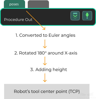
This command obtains vision result, namely, a series of vision points, from Mech-Vision. The object pose of the vision point (namely, the output of the poses port of the Output Step) will be automatically converted to the robot’s TCP by the vision system. The process is as follows.
| If the first input port of the Output Step is Object Center Points, the Output Step will convert the object center points into the corresponding pick points. Therefore, the object poses obtained by running this command are actually poses of pick points, instead of poses of object center points. |
-
Convert the object pose from a quaternion to Euler angles.
-
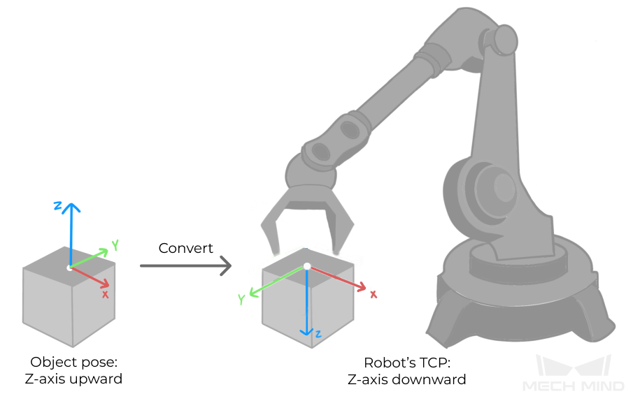
Rotate the object’s pose around the X-axis by 180° to orient its Z-axis downward.
Calling Sequence
This command should be called after Run Mech-Vision Project. After you call this command, call Store Vision Result or Planned Path (TCP) to access pose data.
Command Format
MM_Get_VisData Job,IrPosNum,IrStatusInput Parameters
Job
Mech-Vision project ID. You can view the project ID of a Mech-Vision project in the Project List section of Mech-Vision. The project ID is the number before the project name.
Output Parameters
IrPosNum
This parameter specifies the ID of the variable I. The variable I that corresponds to the ID stores the number of vision points returned by Mech-Vision.
|
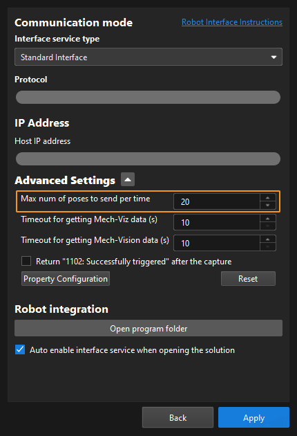
By default, after the robot sends this command, the vision system returns the result in 10 seconds. If the vision system fails to return any result in 10 seconds, a timeout error code is returned. To modify the default timeout period as needed, go to Robot and Communication > in the toolbar of Mech-Vision. 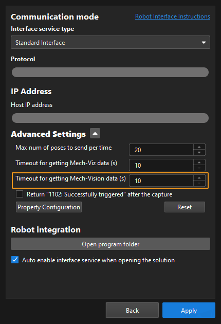
|
Store Vision Result or Planned Path (TCP)
Command
This command stores the TCP, label, and tool ID of the vision point or waypoint in the variables.
Command Format
MM_Get_Pose Serial,PrNum,IrLabel,IrToolIdInput Parameters
Serial
This parameter specifies the index number of a vision point or waypoint, i.e., it copies the tool pose, label, and end‑effector tool number corresponding to that index into the specified variable. Indexes start from 1.
Output Parameters
PrNum
The parameter specifies the ID of the variable P. The variable P that corresponds to the ID stores the TCP of the vision point or waypoint that corresponds to the index.
IrLabel
This parameter specifies the ID of the variable I. The variable I that corresponds to the ID stores the label of the vision point or waypoint that corresponds to the index.
IrToolId
This parameter specifies the ID of the variable I. The variable I that corresponds to the ID stores the tool ID of the vision point or waypoint that corresponds to the index.
Store Planned Path (joint positions)
Command
This command stores the joint positions, label, and tool ID of the waypoint in the variables.
Command Format
MM_Get_Jps Serial,JrNum,IrLabel,IrToolIdInput Parameters
Serial
This parameter specifies the index of the waypoint. The joint positions, label, and tool ID of the waypoint that corresponds to the index are stored in the variables. Indexes start from 1.
Output Parameters
JrNum
This parameter specifies the ID of the variable J. The variable J that corresponds to the ID stores the joint positions of the waypoint that corresponds to the index.
IrLabel
This parameter specifies the ID of the variable I. The variable I that corresponds to the ID stores the label of the waypoint that corresponds to the index.
IrToolId
This parameter specifies the ID of the variable I. The variable I that corresponds to the ID stores the tool ID of the waypoint that corresponds to the index.
Switch Mech-Vision Parameter Recipe
Command
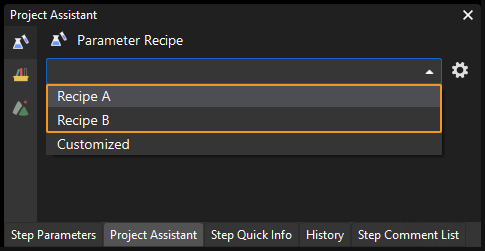
This command triggers Mech-Vision to switch the parameter recipe used by the project. The image below shows how to manually switch the parameter recipe for a Mech-Vision project. For details about parameter recipes, see the parameter recipe guide.
Calling Sequence
This command should be called before Run Mech-Vision Project.
Command Format
MM_Set_Model Job,ModelIndexInput Parameters
Job
Mech-Vision project ID. You can view the project ID of a Mech-Vision project in the Project List section of Mech-Vision. The project ID is the number before the project name.
ModelIndex
This parameter indicates the parameter recipe ID in the Mech-Vision project. For details on how to check the parameter recipe ID, see View the Parameter Recipe ID.
Get Planned Path in Mech-Vision
Command
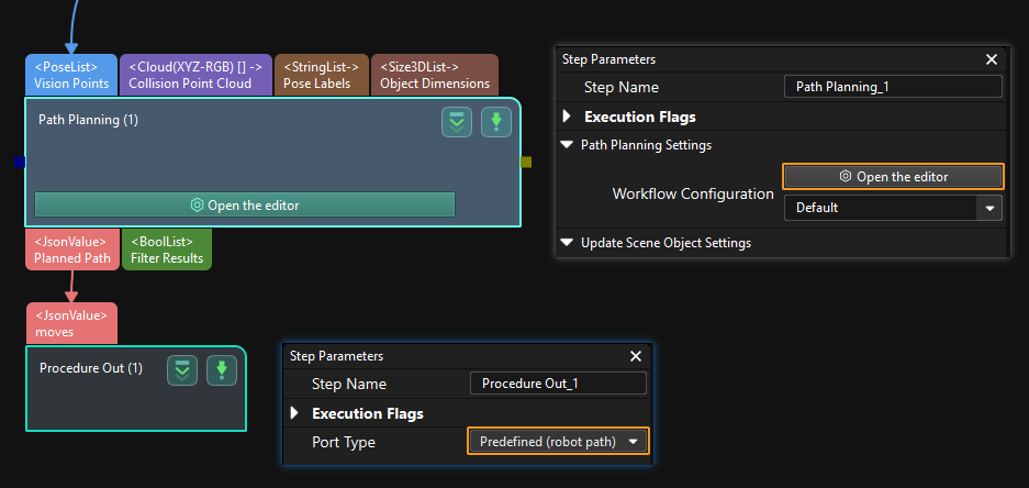
This command obtains the path planned by the Mech-Vision project as a series of waypoints. The path is planned by the path planning tool, which you may enter by clicking Config wizard as shown in the image below. For details about Path Planning, see Path Planning.
| Set the Port Type parameter of the Output Step in Mech-Vision to Predefined (robot path). |
Calling Sequence
This command should be called after Run Mech-Vision Project. After you call this command, call Store Vision Result or Planned Path (TCP) or Store Planned Path (joint positions) to access pose data.
Command Format
MM_Get_VisPath Job,Jps_Pos,IrPosNum,IrVisPos_Num,IrStatusInput Parameters
Job
Mech-Vision project ID. You can view the project ID of a Mech-Vision project in the Project List section of Mech-Vision. The project ID is the number before the project name.
Jps_Pos
This parameter specifies the type of waypoint poses to be obtained. can be set to 1 or 2.
-
1: joint positions. After you run this command, run Store Planned Path (joint positions) to access joint position data.
-
2: tool poses. After you run this command, run Store Vision Result or Planned Path (TCP) to access tool pose data.
Output Parameters
IrPosNum
This parameter specifies the ID of the variable I. The variable I that corresponds to the ID stores the number of waypoints returned by the vision system. By default, the vision system sends no more than 20 waypoints at a time. Therefore, the maximum default value of this parameter is 20. To modify the default maximum number of poses to obtain each time as needed, go to Robot and Communication > in the toolbar of Mech-Vision. The upper limit is 30.
| Before you call Get Planned Path in Mech-Vision, set pos_num_need of Run Mech-Vision Project to 0 to reduce the number of Get Planned Path in Mech-Vision calls. If pos_num_need of Run Mech-Vision Project is set to 1, only one waypoint is obtained each time you call Get Planned Path in Mech-Vision. You need to call Command 105 several times to obtain all waypoints. |
IrVisPos_Num
This parameter specifies the ID of the variable I. The variable I corresponding to the ID stores the sequence number of the Vision Move waypoint that corresponds to the Vision Move step of the path planning tool in the path. If the waypoint does not exist in the path, the petameter value is 0.
If the planned path consists of the following waypoints in sequence: Fixed-Point Move_1, Fixed-Point Move_2, Vision Move, and Fixed-Point Move_3, the sequence number of the Vision Move waypoint is 3.
|
By default, after the robot sends this command, the vision system returns the result in 10 seconds. If the vision system fails to return any result in 10 seconds, a timeout error code is returned. To modify the default timeout period as needed, go to Robot and Communication > in the toolbar of Mech-Vision.
|
Example
MM_Get_VisPath 2,2,51,52,53In the preceding example, the planned path of the Mech-Vision project No.2 is returned, the waypoints of the path are stored in the TCP format, the number of waypoints is stored in I[51], and the sequence number of the Vision Move waypoint in the planned path is stored in I[52].
Get Mech-Vision Custom Data
Command
This command obtains data from the custom port(s) of the Output Step in Mech-Vision. One command call saves all port data of the Output Step to robot memory.
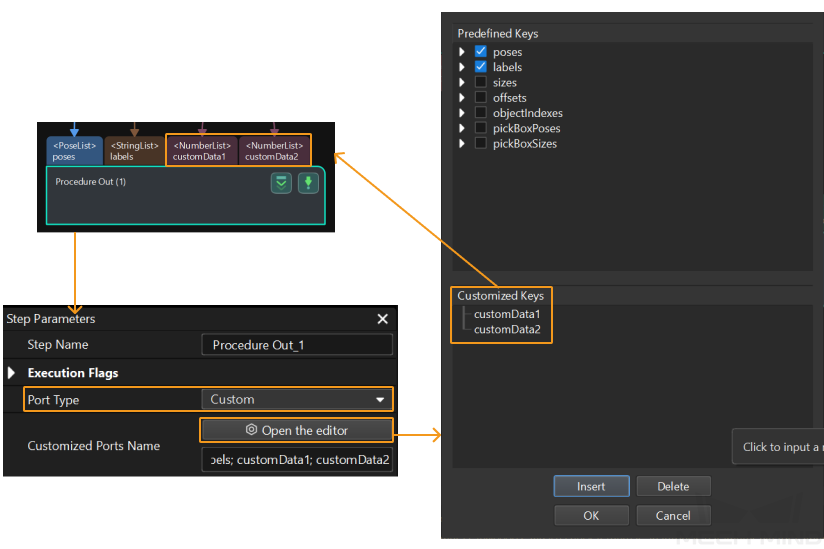
Select the Output Step, set Port Type to Custom, and then click Open the editor to go to the custom port configuration window. The Customized Keys section of the window displays custom port names, such as customeData1 and customeData2 as shown in the following figure.
|
Calling Sequence
This command should be called after Run Mech-Vision Project. After you call this command, call Store Mech-Vision Custom Data to access custom data.
Command Format
MM_Get_Dydata Job,IrPosNum,IrStatusExample
MM_Get_Dydata 2,60,61In the preceding example, the vision result of the Mech-Vision project with an ID of 2 is returned, and the vision point quantity is stored in I[60].
|
The custom port outputs are arranged in the alphabetical order of the names of custom ports. For example, the custom data ports are named as follows:
The transmitted data will be sorted alphabetically by custom name as follows: …aData, bData, cData… |
Store Mech-Vision Custom Data
Calling Sequence
This command should be called after Get Mech-Vision Custom Data.
Command Format
MM_Get_DyPose Serial,PrNum,IrLabel,FrNumInput Parameters
Serial
This parameter specifies the index of the vision point. The custom data of the vision point that corresponds to the index is stored in the variable. Indexes start from 1.
Output Parameters
PrNum
The parameter specifies the ID of the variable P. The variable P that corresponds to the ID stores the TCP of the vision point or waypoint that corresponds to the index.
IrLabel
This parameter specifies the ID of the variable I. The variable I that corresponds to the ID stores the label of the vision point that corresponds to the index. If no label ports are specified in Mech-Vision, 0 is used.
FrNum
This parameter specifies the starting ID of variable Fs. Variable Fs starting with the one with this ID sequentially store custom data of the vision points that correspond to the specified indexes. When you set this parameter, take note of the number of custom elements to make sure that enough variable Fs can be used to store the custom data.
Get Gripper DO List
Command
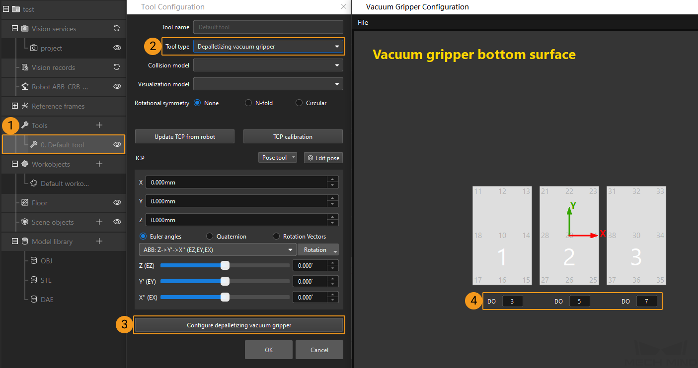
This command obtains the control signal list for the multi-section vacuum gripper from the Mech-Viz project. The robot applies the DO signals obtained by Set Gripper DO List as the tool.
Before using this command, you must perform the following configurations in Mech-Viz.
-
Configure the Mech-Viz project
-
In the Vision Move Step of Mech-Viz, set Select Picking Method to Box depalletizing.

-
In Mech-Viz, double-click the tool name, select Depalletizing vacuum gripper for Tool type, click Configure depalletizing vacuum gripper, and then configure the DO signal values according to needs.
-
Calling Sequence
-
This command must be called before the Get Planned Path in Mech-Vision, Get Planned Path in Mech-Viz, or Get Vision Move Data or Custom Data command. This means that the robot must obtain the motion path and then obtain gripper DO signals of the Vision Move waypoint.
-
This command should be called before Set Gripper DO List.
Set Gripper DO List
Command
This command sets obtained DO signals to general-purpose output signals. In addition, the I/O signals of the robot must be set to the general-purpose output type (UOUT type) starting from IO24.
Calling Sequence
This command should be called after Get Gripper DO List.
Run Mech-Viz Project
Command
This command triggers the Mech-Viz project to run. Mech-Viz plans a path for the robot based on the vision results output by Mech-Vision.
| Right-click the project name in the project resource panel in Mech-Viz and select Autoload Project. |
Command Format
MM_Start_Viz Send_Pos_Type,JrNumInput Parameters
Send_Pos_Type
This parameter specifies the way in which the real robot pose is sent to the Mech-Viz project. Valid values: 0, 1, and 2. The following table describes the details.
| Robot pose type | Description | Applicable scenario |
|---|---|---|
0 |
This command does not need to send the robot pose to the Mech-Viz project. The simulated robot in the Mech-Viz project will move from the set home position to the first waypoint. |
This setting is recommended when the camera is mounted in eye to hand mode. |
1 |
In this command, the robot sends its current joint positions and flange pose to the Mech-Viz project. The simulated robot in Mech-Viz moves from the input joint positions to the first waypoint. |
This setting is recommended when the camera is mounted in eye in hand mode. |
2 |
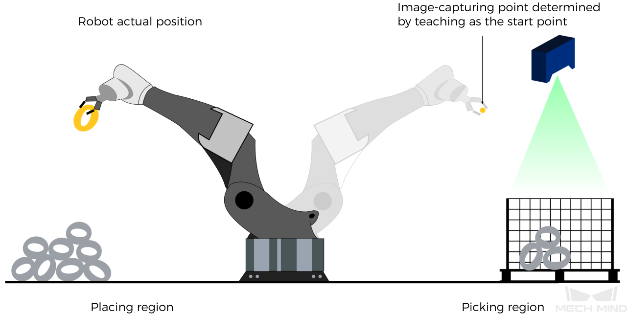
In this command, the robot sends the joint positions of a teach point (the custom joint positions, instead of the current joint positions) to the Mech-Viz project. The Mech-Viz project uses the input joint positions to plan the next path in advance while the robot is not in the camera capture region, as shown in the following figure. The simulated robot in Mech-Viz moves from the input joint positions to the first waypoint. |
This setting is recommended when the camera is mounted in eye to hand mode. |
Why robot pose type 2 is recommended when the camera is mounted in eye to hand mode?
In eye to hand mode, the camera can perform image capturing for the next round of path planning before the robot returns to the image capture region and picking region, thus shortening the cycle time. The image below demonstrates how a robot works in the placing region.
If Send_Pos_Type is set to 1, the robot will send the current pose to Mech-Viz. It is possible that the real robot moves to other positions before reaching the first waypoint. However, the simulated robot moves directly to the first waypoint of the Mech-Viz project from the pose sent by the robot. Consequently, there may be a mismatch between the paths of the real robot and simulated robot. This mismatch can potentially lead to unpredicted safety hazards, especially if collision is detected in the path of the simulated robot.
On the other hand, if Send_Pos_Type is set to 2, the robot will send the image-capturing pose set by teach to Mech-Viz. Thus, the real robot can trigger the next round of path planning in Mech-Viz when the real robot is in the image-capturing region and the cycle time can be shortened.
In conclusion, robot pose type should be set to 2 for projects in eye to hand mode.
JrNum
This parameter specifies the ID of the variable J. The variable J that corresponds to the ID stores custom joint positions.
-
If Send_Pos_Type is set to 2, the joint positions represented by this J variable will be sent to the Mech-Viz project as the start point, where the robot moves from this start point to the first waypoint of the planned path.
-
If Send_Pos_Type is set to a parameter value other than 2, the joint positions are of no practical use but the J variable ID must be set.
Set Exit Port for Branch by Msg Step in Mech-Viz
Command
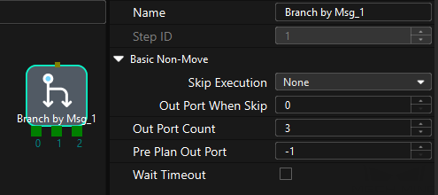
This command sets the exit port for the “Branch by Msg” Step. When the next Step is a “Branch by Msg” Step, the Mech-Viz project will wait for this command to specify the exit port to take.
Calling Sequence
This command should be called after Run Mech-Viz Project.
Command Format
MM_Set_Branch Branch_Num,Export_NumInput Parameters
Branch_Num
This parameter specifies the “Branch by Msg” Step by its ID. Valid values: positive integers. The Step ID is displayed in the Step parameter panel. For example, the Step ID of the Step in the image above is 1.
Export_Num
This parameter indicates the exit port of the Branch by Msg Step. Valid values: positive integers. When the parameter value is set to N, the Mech-Viz project exits from the port with an ID of N-1 of the Branch by Msg Step.
Set Current Index in Mech-Viz
Command
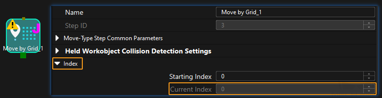
This command sets the value of the Current Index parameter of index-type Steps. Steps that include the Index section include Move by Grid, Move by List, Custom Pallet Pattern, and Predefined Pallet Pattern.
Calling Sequence
Index-type Steps are often preceded by a Branch by Msg Step. The robot should call commands in this order: Run Mech-Viz Project, Set Current Index in Mech-Viz, and Set Exit Port for Branch by Msg Step in Mech-Viz. This is to ensure that Mech-Viz has enough time to set the Current Index value.
Command Format
MM_Set_Index Skill_Num,Index_NumInput Parameters
Skill_Num
This parameter specifies the Step ID of the Index-type Step. Valid values: positive integers. The Step ID is displayed in the Step parameter panel. For example, the Step ID of the Step in the image above is 3.
Index_Num
This parameter sets the value of the Current Index parameter of index-type Steps. Valid values: positive integers. When this parameter value is set to N, the current index of the corresponding Step is N-1.
Get Planned Path in Mech-Viz
Command
This command obtains the path planned by the Mech-Viz project as a series of waypoints.
|
Waypoint: Each point that the robot reaches when moving along the planned path. A waypoint has information including the robot pose, label, and motion type. Waypoints can be divided into two categories:
|
Calling Sequence
This command should be called after Run Mech-Viz Project. After you call this command, call Store Vision Result or Planned Path (TCP) or Store Planned Path (joint positions) to access pose data.
Command Format
MM_Get_VizData Jps_Pos,IrPosNum,IrVisPos_Num,IrStatusInput Parameters
Jps_Pos
This parameter specifies the type of waypoint poses to be obtained. can be set to 1 or 2.
-
1: joint positions. After you run this command, run Store Planned Path (joint positions) to access joint position data.
-
2: tool poses. After you run this command, run Store Vision Result or Planned Path (TCP) to access tool pose data.
Output Parameters
IrPosNum
This parameter specifies the ID of the variable I. The variable I that corresponds to the ID stores the number of waypoints returned by the vision system. By default, the vision system sends no more than 20 waypoints at a time. Therefore, the maximum default value of this parameter is 20. To modify the default maximum number of poses to obtain each time as needed, go to Robot and Communication > in the toolbar of Mech-Vision. The upper limit is 30.
IrVisPos_Num
This parameter specifies the ID of the variable I. The variable I corresponding to the ID stores the sequence number of the Vision Move waypoint that corresponds to the Vision Move step of the Mech-Viz project in the path. If the waypoint does not exist in the path, the petameter value is 0.
If the planned path consists of the following waypoints in sequence: Fixed-Point Move_1, Fixed-Point Move_2, Vision Move, and Fixed-Point Move_3, the sequence number of the Vision Move waypoint is 3.
|
By default, after the robot sends this command, the vision system returns the result in 10 seconds. If the vision system fails to return any result in 10 seconds, a timeout error code is returned. To modify the default timeout period as needed, go to Robot and Communication > in the toolbar of Mech-Vision. 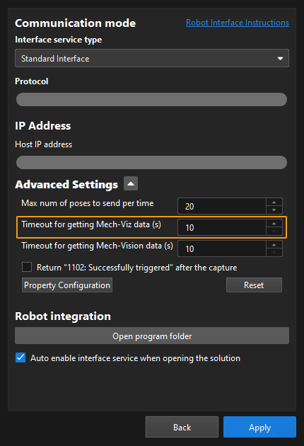
|
Get Vision Move Data or Custom Data
Command
This command obtains data output by the Vision Move Step or the custom port(s) of the Output Step from the Mech-Viz project. One command call stores all data in robot memory.
|
-
Vision Move data refers to data output by the Vision Move Step in Mech-Viz, including the labels of picked target objects, number of picked target objects, number of target objects to be picked this time, edge or corner ID of vacuum gripper, TCP offset, orientation of target object group, orientation of target object, and dimensions of target object group.
-
Custom data refers to data output by the custom port(s) of the Output Step in Mech-Vision and then forwarded by Mech-Viz.
Select the Output Step, set Port Type to Custom, and then click Open the editor to go to the custom port configuration window. The Customized Keys section of the window displays custom port names, such as customeData1 and customeData2 as shown in the following figure.
-
Data output from Predefined Keys, such as poses, labels, sizes, offsets, is not custom data.
-
You must set Port Type of the Output Step to Custom and select the poses port in the Predefined Keys section in Mech-Vision.
-
Calling Sequence
This command should be called after Run Mech-Viz Project.
Command Format
MM_Get_Plandata Jps_Pos,IrPosNum,IrVisPos_Num,IrStatusInput Parameters
Jps_Pos
This parameter specifies the expected format of the returned data. The value range is 1 to 4. See the following content for details.
Parameter value of Jps_Pos |
Description of expected returned data (Each field is explained below. If the Mech-Vision project does not have a custom port, no elements of custom data are returned.) |
|
Waypoint type |
Returned data |
|
1 |
Non-Vision Move waypoint |
Pose (JPs), motion type, tool ID |
Vision Move waypoint |
Pose (joint positions), motion type, tool ID, velocity, element 1 in custom data, … element N in custom data |
|
2 |
Non-Vision Move waypoint |
Pose (TCP), motion type, tool ID, velocity |
Vision Move waypoint |
Pose (TCP), motion type, tool ID, velocity, element 1 in custom data, … element N in custom data |
|
3 |
Non-Vision Move waypoint |
Pose (JPs), motion type, tool ID, velocity |
Vision Move waypoint |
Pose (joint positions), motion type, tool ID, velocity, Mech-Viz Vision Move data, element 1 in custom data, … element N in custom data |
|
4 |
Non-Vision Move waypoint |
Pose (TCP), motion type, tool ID, velocity |
Vision Move waypoint |
Pose (TCP), motion type, tool ID, velocity, Mech-Viz Vision Move data, element 1 in custom data, … element N in custom data |
|
|
Pose The pose of a waypoint can be joint positions (measured in degrees) or TCP (measured in millimeters for three-dimensional coordinates and in degrees for Euler angles) of the robot. Motion type The motion type of the robot. Valid values: 1 and 2.
Tool ID The ID of the tool to be used at this waypoint. A value of -1 means that no tool is used at this waypoint. Velocity The parameter value, represented in percentage, equals the velocity set for a move-type Step multiplied by the global velocity set in Mech-Viz. Vision Move data Data output by the Vision Move Step in Mech-Viz, including labels of picked target objects, number of picked target objects, number of target objects to be picked this time, edge or corner ID of vacuum gripper, TCP offset, orientation of target object group, orientation of target object, and dimensions of target object group.
Elements in custom data The data of all custom ports of a single vision point. For example, data output from ports of the Output Step is presented in the following table. The elements in custom data of the first vision point are [0, 0, 1] and [0, 0]; and the elements in custom data of the second vision point are [1, 0, 0] and [1, 1].
|
Output Parameters
IrPosNum
This parameter specifies the ID of the variable I. The variable I that corresponds to the ID stores the number of waypoints that are returned by the vision system.
IrVisPos_Num
This parameter indicates the sequence number of the Vision Move waypoint (i.e., the waypoint corresponding to the “Vision Move” Step) in the planned path. The data type is num. If the path does not contain a “Vision Move” waypoint, the value of this parameter is 0.
For example, if the planned path consists of the following waypoints: "Fixed-Point Move_1", "Fixed-Point Move_2", "Vision Move", "Fixed-Point Move_3", the sequence number of the Vision Move waypoint is 3.
IrStatus
This parameter specifies the ID of the variable I. The variable I that corresponds to the ID stores the command execution status code. Status code 1103 is returned if the command is executed successfully and the path planning data is returned from the Mech-Vision project. Status code 2100 is returned if the command is executed successfully and the path planning data or custom data is returned from the Mech-Viz project. If a command fails to be run, a specific error code is returned. For details, see Status Codes and Troubleshooting.
Store Vision Move Data or Custom Data
Command
After calling the Get Vision Move Data or Custom Data command, this command is used to save the waypoint data to specified variables.
Calling Sequence
This command should be called after Get Vision Move Data or Custom Data.
Command Format
MM_Get_PlanPoseJps Serial,PJrNum,IrLabel,FrNumInput Parameters
Serial
This parameter specifies the index of the waypoint. The joint positions of the waypoint that corresponds to the index are stored in the variables. Indexes start from 1.
Output Parameters
PJrNum
The parameter specifies the ID of the variable P or J. The variable that corresponds to the ID stores the pose data of the waypoint that corresponds to the specified index.
-
If Jps_Pos is set to 1 or 3 in MM_Get_Plandata, this parameter specifies the ID of variable J.
-
If Jps_Pos is set to 2 or 4 in MM_Get_Plandata, this parameter specifies the ID of variable P.
IrLabel
This parameter specifies the starting ID of variable Is. Variable Is starting with the one with this ID sequentially store the motion types, tool IDs, and velocities of the waypoints that correspond to the indexes. When you set this parameter, make sure that the first three variables that labeled with consecutive starting IDs are not affected by other factors.
FrNum
This parameter specifies the starting ID of variable Fs. The variable Fs starting with the one with this ID sequentially store Vision Move data and custom data of the waypoints that correspond to the specified indexes.
Skip this parameter for non-Vision Move waypoints. In addition, when you set this parameter, take note of the total number of variables to make sure that enough variable Fs can be used to store data. Vision Move data takes up 21 variables, and custom data takes up condition-specific number of variables.
The following table details Vision Move data.
| Value | Description | Number of occupied variables |
|---|---|---|
Labels of picked target objects |
A label consists of 10 integers. The default value is ten 0s. |
10 |
Number of picked target objects |
The total number of picked target objects. |
1 |
Number of target objects to be picked this time |
Number of target objects to be picked this time |
1 |
Edge or corner ID of vacuum gripper |
The ID of the edge or corner used to pick target objects this time. |
1 |
TCP offset |
The XYZ offset between the center of the target object group and the tool pose center. |
3 |
Orientation of target object group |
The relative position between the target object group and the length of the vacuum gripper. The value is 0 or 1, where 0 stands for parallel and 1 for vertical. |
1 |
Orientation of target object |
The relative position between the length of a target object and that of the vacuum gripper. The value is 0 or 1, where 0 stands for parallel and 1 for vertical. |
1 |
Dimensions of target object group |
The length, width, and height of the target object group to be picked this time. |
3 |
Example
MM_Get_PlanPoseJps 2,60,60,60In the preceding example, the pose data, motion type, tool ID, and velocity of the second waypoint are stored in P[60], I[60], I[61], and I[62] respectively. If the waypoint is not a Vision Move waypoint, no Vision Move data is returned; if the waypoint is a Vision Move waypoint, the corresponding Vision Move data and custom data are stored in the numeric registers starting from F[60].
Calibration
Command
This command is used for robot hand-eye calibration (extrinsic parameter calibration). This command must be used together with the Camera Calibration setting to complete automatic calibration. You can find Camera Calibration in the toolbar of Mech-Vision. For more information, see DENSO Automatic Calibration.
Command Format
Calibration MoveType,PosJps,WaitTime,AxisNum,AxisVal,Pr_serialInput Parameters
MoveType
This parameter specifies the motion type of the robot. Valid values: 1 and 2.
-
1: Linear motion (MOVEL)
-
2: Joint motion (MOVEJ)
PosJps
This parameter specifies the type of calibration point poses to be obtained. Valid values: 1 and 2.
-
1: TCP
-
2: Joint positions
WaitTime
This parameter specifies the time the robot waits to avoid shaking after it moves to the calibration point. The default value is 2 (s).
AxisNum
This parameter specifies the number of the robot axes.
AxisVal
This parameter specifies the external axis data. Unit: millimeters. If a 7th axis exists and is controlled by the robot on site, this parameter must be set to the specific external exist data. Otherwise, this parameter must be set to 0.
Pr_serial
The parameter specifies the ID of the variable P. The P variable that corresponds to the ID stores the pose data of the calibration point. The default value is 4, which indicates that the pose data of the P[4] calibration point is used.
Example
Calibration 2,1,2,6,0,4In the preceding example, the pose data of the calibration point is represented in TCP. The robot moves to the calibration point based on the joint positions of the robot and then waits for 2 seconds. No external axes exist. The pose data of the calibration point is stored in P[4].