Master-Control Communication Setup
This guide shows you how to load the Master-Control program to a MELFA robot, and set up the Master-Control communication between the robot and the Mech-Mind Vision System.
| In this section, you will load the robot Master-Control program and the configuration files to the robot system to establish the Master-Control communication between the vision system and the robot. |
Preparation
Set up the Network Connection
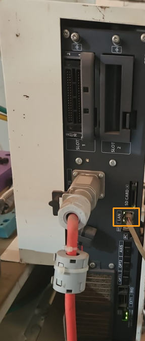
Connect the Hardware
Use the Ethernet cable to connect the network ports of the IPC and the robot controller.
Set the IP Address on the IPC
The default IP address of the MELFA robot is 192.168.0.20. Therefore, set the IPC’s IP address to one on the subnet 192.168.0.0/255.255.255.0.
| The IP addresses of the IPC and the robot should be on the same subnet, but do not set the same IP addresses. |
Create and Configure the Project
In this guide, the Master-Control program is loaded into the robot via the software RT ToolBox3. Therefore, before loading the program, you need to install RT ToolBox3.
-
Install the software RT ToolBox3 onto the IPC.
You may contact the robot manufacturer to obtain the software RT ToolBox3. -
Open RT ToolBox3. Click New on the menu bar, enter the workspace name, and then click OK.
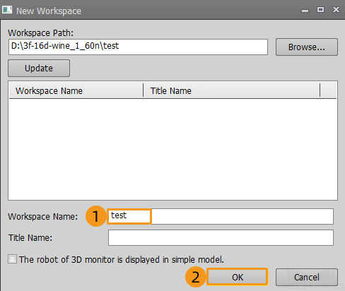
-
Click Robot Model on the left panel, and select the Series, Type, Maximum Load and Robot Model of the robot in use.
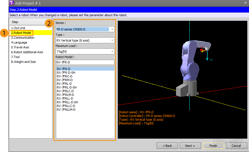
-
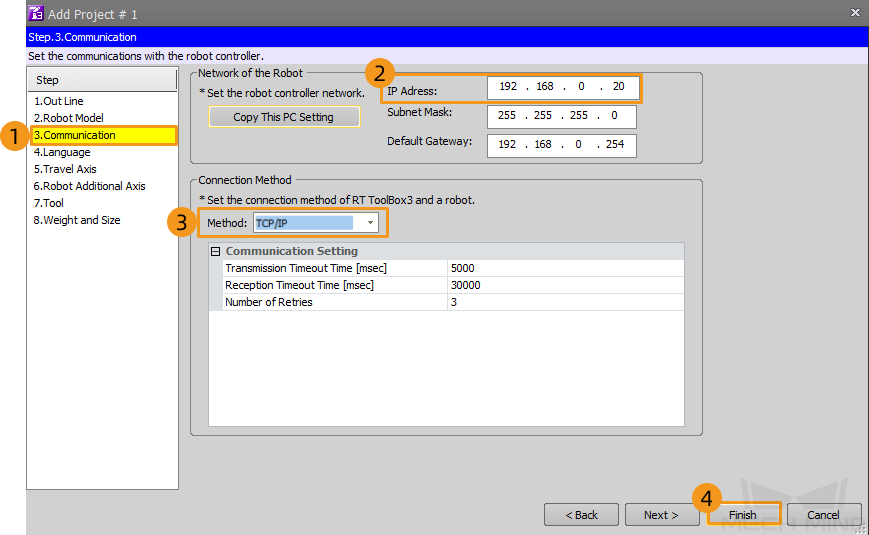
Click Communication on the left bar and check the robot’s IP address. Ensure that the robot’s and IPC’s IP addresses are on the same subnet. Set the connection method to TCP/IP. Then, click Finish.
-
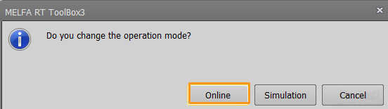
When the dialogue box as follows pops up, click Online to connect the robot in use.
Load the Program Files to the Robot
-
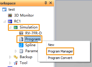
On the Workspace panel, click .
-
Finish the steps below in the pop-up window.
-
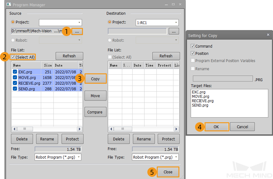
Click ....
-
In the pop-up file browser, go to
Communication Component/Robot_Server/Robot_FullControlfrom the installation directory of Mech-Vision & Mech-Viz. Select the folder melfa and click OK. -
Select (Select All).
-
Click Copy.
-
Click OK in the pop-up window. The copied files will show up in the file list area on the right. Then, click Close.
-
Now, the Master-Control program and configuration files are loaded into the robot system.
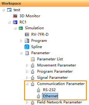
Configure Ethernet
-
Click on the left Workspace panel.
-
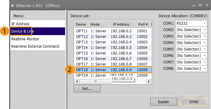
Click Device & Line on the left menu, and then double-click the line OPT18.
-
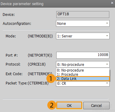
In the pop-up window, set Protocol to Data Link, and click OK.
-
Set Protocol of the device OPT19 to Data Link following the steps above.
-
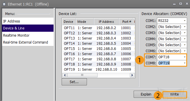
In the Ethernet window, set the value of COM7 to OPT18 and the value of COM8 to OPT19, and click Write.
-
Click (Y) in the pop-up dialogue box.
The robot automatically restarts after writing the program. 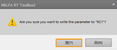
Test Master-Control Communication
Run the Program
-
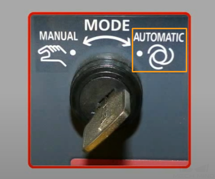
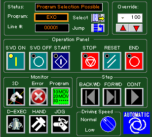
Switch the key on the robot controller to the AUTOMATIC mode.
-
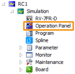
Click in the workspace panel of RT ToolBox3.
-
Click the Select icon in the operation panel. Select EXC in the pop-up window and click OK.
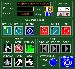
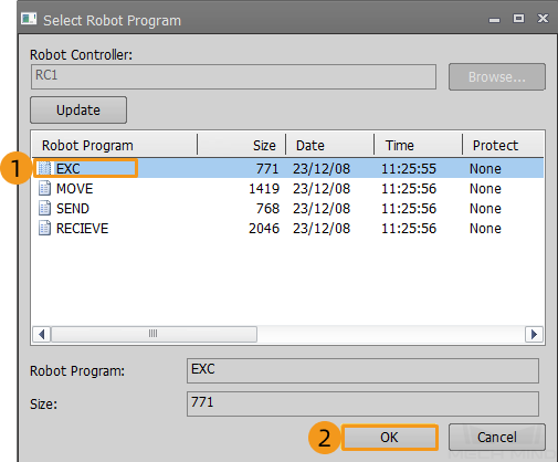
After that, EXC will display in the Program text box.
-
Click SVO ON, and then click START.

Create a Mech-Viz Project
-
Open Mech-Viz, press Ctrl + N on the keyboard to create a new project. Select the robot model corresponding to your real robot brand and model on the interface as shown below.

-
Press Ctrl + S and create or select a folder to save the project.
-
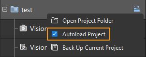
Right-click the project name in the left panel in Mech-Viz and select Autoload Project.
Connect to the Robot
-
Click Master-Control Robot on the toolbar of Mech-Viz.
-
Input the IP address of the real robot in Robot IP address (the IP address in the picture is only an example). Click Connect the robot.

If Mech-Viz successfully connects the real robot, the current status will change to Connected. Meanwhile, the icon in the toolbar will turn from blue to green.
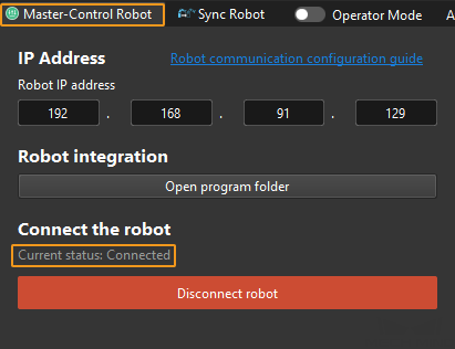
If the connection fails, please double-check the robot IP address.
Move the Robot
-
In the toolbar of Mech-Viz, change the “Vel.” (velocity) and “Acc.” (acceleration) parameters to 5%.

-
Click Sync Robot in the toolbar, and you can synchronize the poses of the simulated robot in the 3D simulation space with the poses of the real robot. Then click Sync Robot again to unselect it.

-
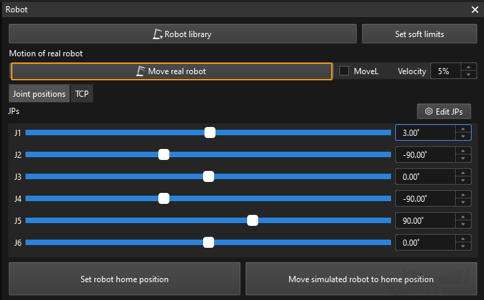
In the Robot tab, slightly adjust the value of “J1”, for example, from 0˚ to 3˚. This operation will move the simulated robot.
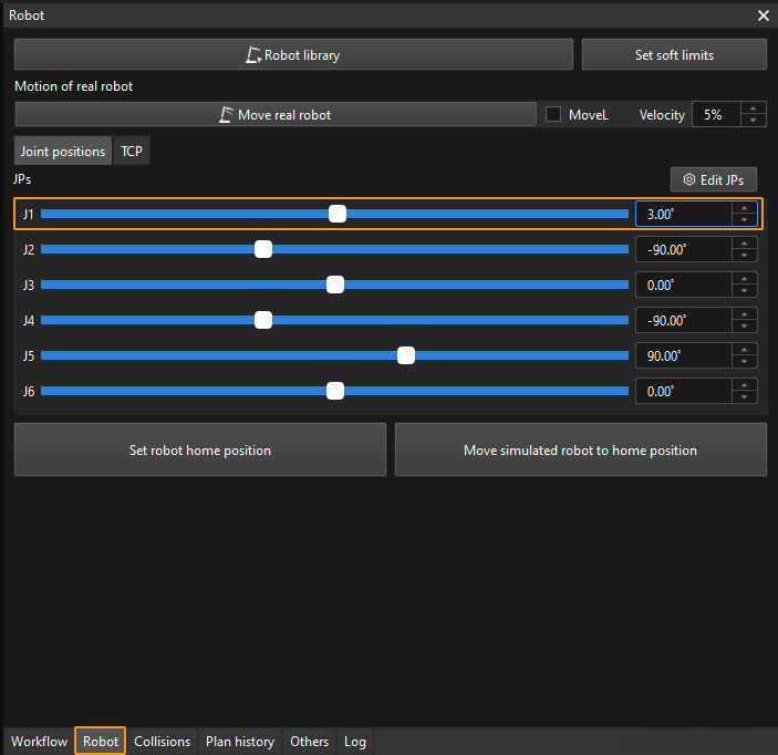
-
Click Move real robot and check if the real robot has moved. If the real robot has reached the JPs set for the simulated robot, the master-control communication is working.
When moving the robot, please ensure the safety of personnel. In the case of an emergency, press the emergency stop button on the teach pendant!