Example Program 11: MM_S11_Viz_Timer
Program Introduction
Description |
The robot uses a timer to calculate the time taken from establishing the communication to completing picking and placing each time. |
File path |
You can navigate to the installation directory of Mech-Vision and Mech-Viz and find the file by using the |
Project |
Mech-Vision and Mech-Viz projects |
Prerequisites |
|
| This example program is provided for reference only. Before using the program, please modify the program according to the actual scenario. |
Program Description
This part describes the MM_S11_Viz_Timer example program.
| The only difference between the MM_S11_Viz_Timer example program and the MM_S2_Viz_Basic example program is that MM_S11_Viz_Timer can use a timer to calculate the required time (this code of this feature is bolded). As such, only the feature of handling errors based on the different error codes is described in the following part. For information about the parts of MM_S6_Viz_ErrorHandle that are consistent with those of MM_S2_Viz_Basic, see Example Program 2: MM_S2_Viz_Basic. |
   1:  !-------------------------------- ;
   2:  !FUNCTION: trigger Mech-Viz ;
   3:  !project and get planned path, ;
   4:  !add a timer to record cycle time ;
   5:  !Mech-Mind, 2023-12-25 ;
   6:  !-------------------------------- ;
   7:   ;
   8:  !set current uframe NO. to 0 ;
   9:  UFRAME_NUM=0 ;
  10:  !set current tool NO. to 1 ;
  11:  UTOOL_NUM=1 ;
  12:  !move to robot home position ;
  13:J P[1] 100% FINE    ;
  14:  !initialize communication ;
  15:  !parameters(initialization is ;
  16:  !required only once) ;
  17:  CALL MM_INIT_SKT('8','127.0.0.1',30000,5) ;
  18:  LBL[1:LOOP] ;
  19:  !reset timer to 0 ;
  20:  TIMER[1]=RESET ;
  21:  !start timer ;
  22:  TIMER[1]=START ;
  23:  !move to image-capturing position ;
  24:L P[2] 1000mm/sec FINE    ;
  25:  !trigger Mech-Viz project ;
  26:  CALL MM_START_VIZ(2,10,53) ;
  27:  !check whether viz project has ;
  28:  !been triggered successfully ;
  29:  IF (R[53]<>2103),JMP LBL[99] ;
  30:  !get planned path, 1st argument ;
  31:  !(1) means getting pose in JPs ;
  32:  CALL MM_GET_VIZ(1,51,52,53) ;
  33:  !check whether planned path has ;
  34:  !been got from Mech-Viz ;
  35:  !successfully ;
  36:  IF R[53]<>2100,JMP LBL[99] ;
  37:  !save waypoints of the planned ;
  38:  !path to local variables one ;
  39:  !by one ;
  40:  CALL MM_GET_JPS(1,60,70,80) ;
  41:  CALL MM_GET_JPS(2,61,71,81) ;
  42:  CALL MM_GET_JPS(3,62,72,82) ;
  43:  !follow the planned path to pick ;
  44:  !move to approach waypoint ;
  45:  !of picking ;
  46:J PR[60] 50% FINE    ;
  47:  !move to picking waypoint ;
  48:J PR[61] 10% FINE    ;
  49:  !add object grasping logic here, ;
  50:  !such as "DO[1]=ON" ;
  51:  PAUSE ;
  52:  !move to departure waypoint ;
  53:  !of picking ;
  54:J PR[62] 50% FINE    ;
  55:  !move to intermediate waypoint ;
  56:  !of placing ;
  57:J P[3] 50% CNT100    ;
  58:  !move to approach waypoint ;
  59:  !of placing ;
  60:L P[4] 1000mm/sec FINE Tool_Offset,PR[2]    ;
  61:  !move to placing waypoint ;
  62:L P[4] 300mm/sec FINE    ;
  63:  !add object releasing logic here, ;
  64:  !such as "DO[1]=OFF" ;
  65:  PAUSE ;
  66:  !move to departure waypoint ;
  67:  !of placing ;
  68:L P[4] 1000mm/sec FINE Tool_Offset,PR[2]    ;
  69:  !move back to robot home position ;
  70:J P[1] 100% FINE    ;
  71:  !stop timer ;
  72:  TIMER[1]=STOP ;
  73:  !save timer value to register ;
  74:  R[99]=TIMER[1]    ;
  75:  JMP LBL[1] ;
  76:  END ;
  77:   ;
  78:  LBL[99:vision error] ;
  79:  !add error handling logic here ;
  80:  !according to different ;
  81:  !error codes ;
  82:  !e.g.: status=2038 means no ;
  83:  !point cloud in ROI ;
  84:  !e.g.: status=3099 means ;
  85:  !failed to open socket ;
  86:  PAUSE ;
The workflow corresponding to the above example program code is shown in the figure below.
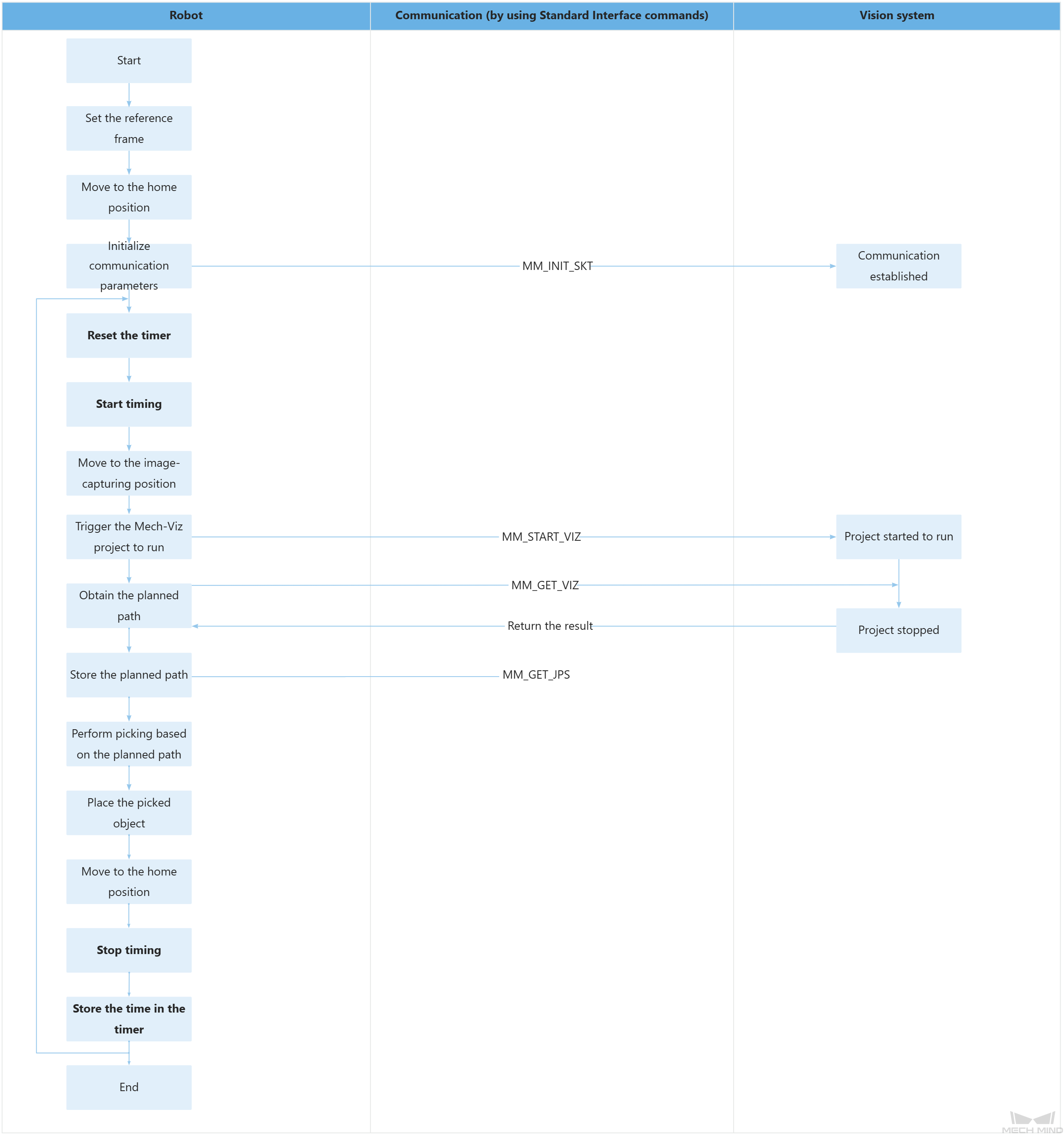
The table below describes the feature of using a timer to calculate the required time.
| Feature | Code and description |
|---|---|
Calculate the time taken from establishing the communication to completing picking and placing each time by looping |
The above code indicates that the program repeatedly executes the code at LBL[1]. The above code resets TIMER[1] to 0. The above code starts running TIMER[1]. The above code stops TIMER[1]. The above code assigns the value of TIMER[1] to the R[99] register, allowing for easy retrieval of the time tracked by the timer (i.e., the time spent from establishing communication to completing the pick-and-place operation). |