Communication Configuration and Example Program Usage
This topic provides two methods on setting up the Standard Interface communication based on the EtherNet/IP protocol between a Beckhoff PLC and the Mech-Mind Vision System.
-
Use a PCI-e card.
-
Configure the software. No cards are required.
|
Hardware and Software Requirements
|
The models and versions listed below are tested and can be used. For other models and versions, you may refer to this guide for operation. If any issues occur, please contact Mech-Mind Technical Support. |
Hardware
If you configure the software to set up the EtherNet/IP communication, click this line to view the required hardware and hardware connection settings.
-
Beckhoff PLC
-
IPC
-
Network switch and Ethernet cables
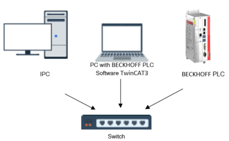
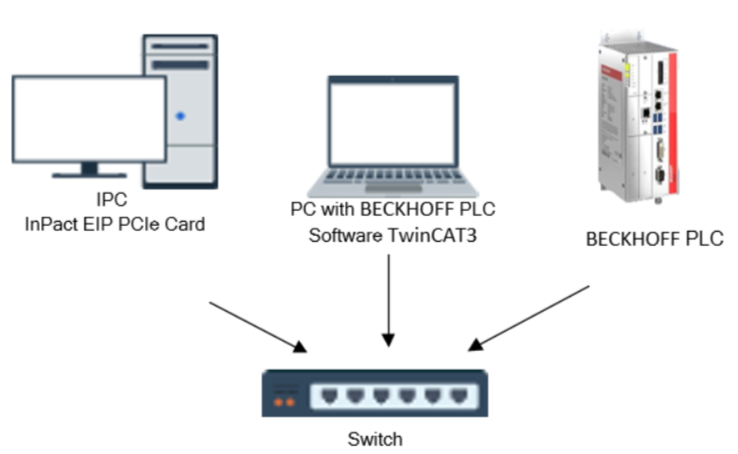
The hardware connection is as follows. Each device has a unique IP address, but all must be in the same subnet and not in use by other devices. For the IP address settings of the PLC, refer to the section below. For the IP address settings of the IPC and the computer with TwinCAT 3 installed, see this link.
If you use a PCI-e card to set up the EtherNet/IP communication, click this line to view the required hardware and hardware connection settings.
-
Beckhoff PLC
-
IPC with HMS IXXAT INpact 40 PCIe interface card (purchased/prepared by yourself) installed
-
Network switch and Ethernet cables
The hardware connection is as follows. Each device has a unique IP address, but all must be in the same subnet and not in use by other devices. For the IP address settings of the PLC and communication card, refer to the section below. For the IP address settings of the IPC and the computer with TwinCAT 3 installed, see this link.
Software
If you configure the software to set up the EtherNet/IP communication, click this line to view the required software.
| Software | Description | Installed Location |
|---|---|---|
TwinCAT 3 |
Beckhoff PLC programming software |
Computer for Beckhoff PLC programming |
Mech-Vision & Mech-Viz (2.0.0 or above) |
Software that provides the Mech-Mind Vision System |
IPC |
Please copy and paste the following files to a PC with TwinCAT 3 installed:
-
Software EIP.eds file: Used to provide the identity information of the IPC in the EtherNet/IP network.
The Software EIP.eds file can be found in the Communication Component/Robot_Interface/EthernetIP/EDSpath in the directory where Mech-Vision and Mech-Viz are installed. -
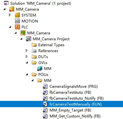
MM_Camera.tpzip: A PLC example program file. After importing this file into TwinCAT 3, you will obtain the following example program files:
-
CameraSignalsMove: Used to transfer the vision system signals.
-
MM_XXX_XXX FB: Used to implement the features of various interface commands.
-
fcCameraTestManually: An example program (manual mode).
-
fbCameraTestAuto: An example program (automatic mode).
-
fbCameraTestAuto_Notify: The sample message that is obtained.
The MM_Camera.tpzipfile is located in the following folder within the Mech-Vision and Mech-Viz software installation path:Communication Component/Robot_Interface/EthernetIP/Programming Samples/BECKHOFF PLC EthernetIP.
-
If you use a PCI-e card to set up the EtherNet/IP communication, click this line to view the required software.
| Software | Description | Installed Location |
|---|---|---|
TwinCAT 3 |
Beckhoff PLC programming software |
Computer for Beckhoff PLC programming |
IXXAT VCI V4 |
Board Driver |
IPC |
Latest official version: IXXAT VCI V4 |
||
Mech-Vision & Mech-Viz (2.0.0 or above) |
Software that provides the Mech-Mind Vision System |
IPC |
Used for setting up the IP address of the PCIe card |
IPC |
Please copy and paste the following files to a PC with TwinCAT 3 installed:
-
005A002B003A0100.EDS file, which is used to provide the identity information of the IPC in the EtherNet/IP network.
The 005A002B003A0100.EDS file can be found in the Communication Component/Robot_Interface/EthernetIP/EDSpath in the directory where Mech-Vision and Mech-Viz are installed. -
MM_Camera.tpzip: A PLC example program file. After importing this file into TwinCAT 3, you will obtain the following example program files:
-
CameraSignalsMove: Used to transfer the vision system signals.
-
MM_XXX_XXX FB: Used to implement the features of various interface commands.
-
fcCameraTestManually: An example program (manual mode).
-
fbCameraTestAuto: An example program (automatic mode).
-
fbCameraTestAuto_Notify: The sample message that is obtained.
The MM_Camera.tpzipfile is located in the following folder within the Mech-Vision and Mech-Viz software installation path:Communication Component/Robot_Interface/EthernetIP/Programming Samples/BECKHOFF PLC EthernetIP.
-
Configure Communication
If you configure the software to set up the EtherNet/IP communication, click this line to view the detailed operations.
-
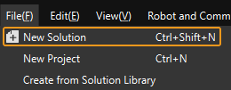
Open Mech-Vision, and you may enter different interfaces. Create a new solution according to the instructions below.
-
If you have entered the Welcome interface, click New blank solution.

-
If you have entered the main interface, click on the menu bar.
-
Click the Select robot dropdown, and choose either Listed robot or Custom robot according to the robot used in your project. Then click Next.
-
Listed robot: Suitable for most robots. Click Select robot model to choose the specific robot model.
-
Custom robot: Suitable for gantry robots or robots not included in the listed robot category. Robot Euler angle convention and robot coordinate system need to be selected.
-
-
-
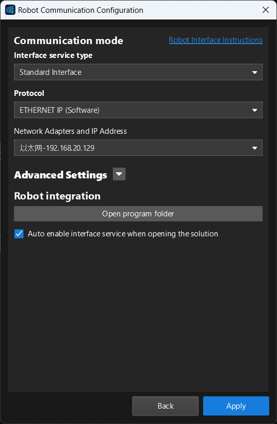
In the Robot Communication Configuration window, complete the following configurations.
-
Click the Select robot drop-down menu, and select Listed robot. Click Select robot model, and select the robot model that you use. Then, click Next.
-
In the Communication mode section, set Interface service type to Standard Interface, set Protocol to ETHERNET IP (Software), and set Network Adapters and IP Address to the network adapter and IP address used by the IPC.
-
(Optional) Select Auto enable interface service when opening the solution.
-
Click Apply.
-
-
On the main interface of Mech-Vision, make sure that the Robot Communication Configuration switch on the toolbar is flipped and has turned blue.

If you use a PCI-e card to set up the EtherNet/IP communication, click this line to view the detailed operations.
Check PCI-e Card and Driver Software
-
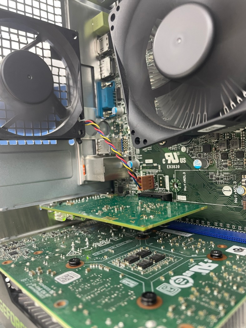
Please make sure that the INpact EIP Slave PCIe interface card has been pressed into the PCI-e slot of the IPC, as shown below.
-
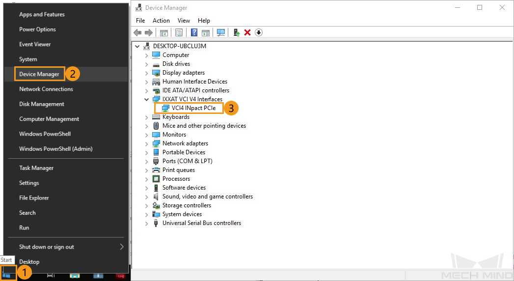
Start the IPC, go to Start ‣ Device Manager and check if the driver software VCI4 INpact PCIe has been installed.
Set up Robot Communication Configuration
-
Open Mech-Vision, and you may enter different interfaces. Create a new solution according to the instructions below.
-
If you have entered the Welcome interface, click New blank solution.
-
If you have entered the main interface, click on the menu bar.
-
-
Click Robot Communication Configuration on the toolbar of Mech-Vision.
-
In the Robot Communication Configuration window, complete the following configurations.
-
Click the Select robot dropdown, and choose either Listed robot or Custom robot according to the robot used in your project. Then click Next.
-
Listed robot: Suitable for most robots. Click Select robot model to choose the specific robot model.
-
Custom robot: Suitable for gantry robots or robots not included in the listed robot category. Robot Euler angle convention and robot coordinate system need to be selected.
-
-
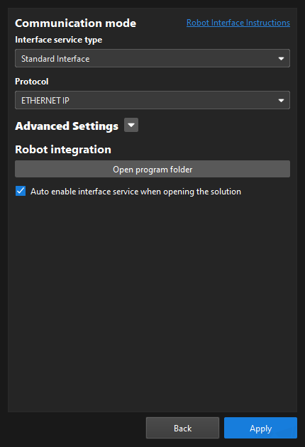
In the Communication mode area, select Standard Interface for Interface service type and select ETHERNET IP for Protocol.
-
(Optional) Select Auto enable interface service when opening the solution.
-
Click Apply.
-
-
On the main interface of Mech-Vision, make sure that the Robot Communication Configuration switch on the toolbar is flipped and turned to blue.
Configure IP address of the PCIe Card
| Ensure the interface service has been enabled before proceeding with the following operations. |
-
Use an Ethernet cable to connect the network ports of the IPC and the INpact EIP Slave PCIe.
After configuring the IP and initiating communication successfully, the Ethernet cable used here can be removed. -
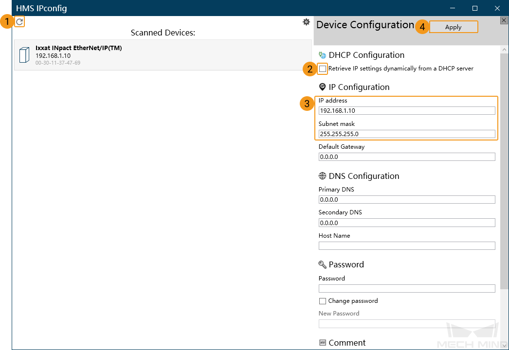
Open HMS IPconfig, click the scan icon and unselect “Retrieve IP settings dynamically from a DHCP server”, and then enter the IP address and subnet mask. After configuration, click Apply and exit the software.
Create and Configure the PLC Project
Create PLC Project
-
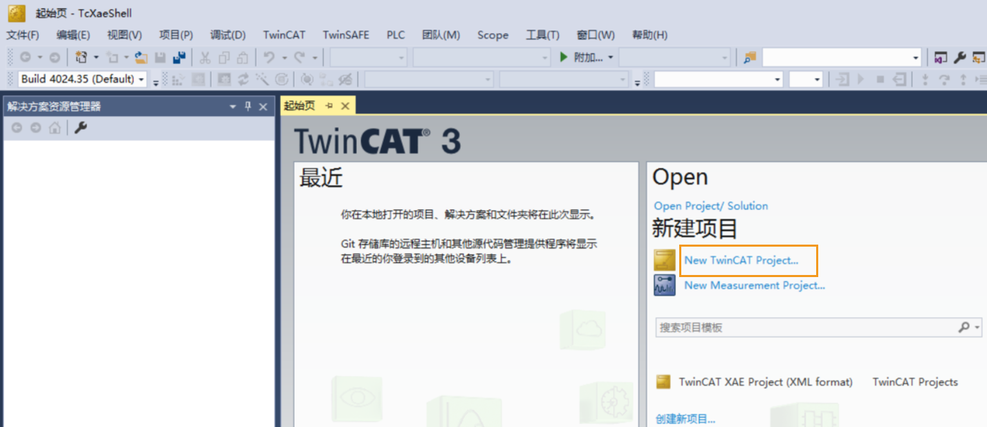
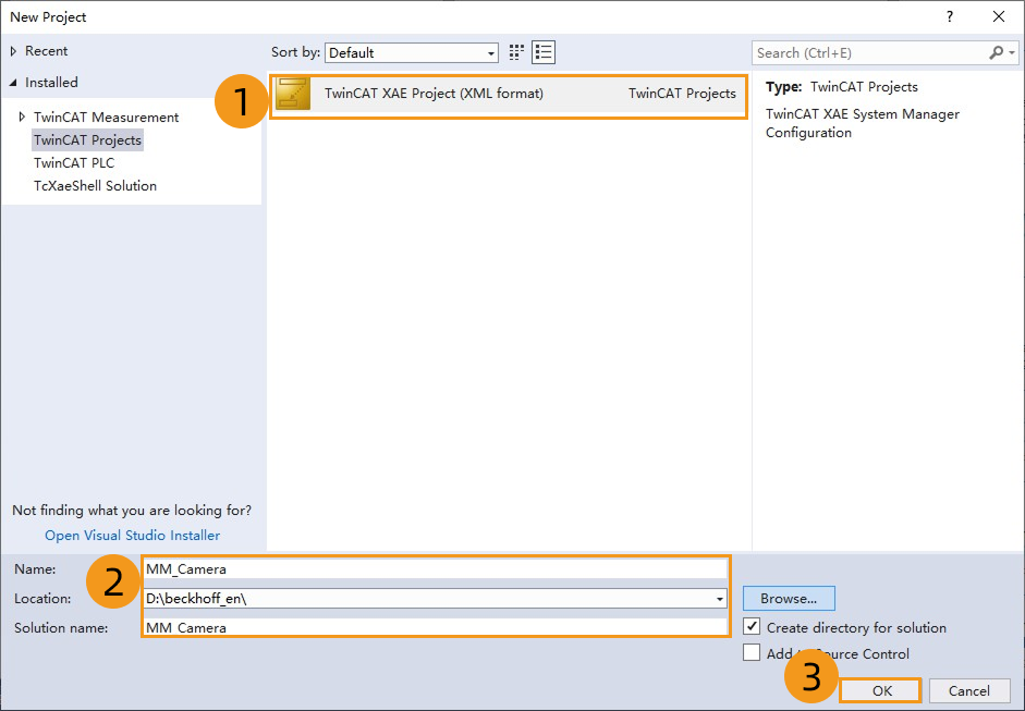
On the computer, open TwinCAT 3 and click New TwinCAT Project. The New Project window will appear.
-
In the following window, select TwinCAT XAE Project (XML format), enter a project name, and then choose a save location as needed. Leave the other options as default and click OK.
-
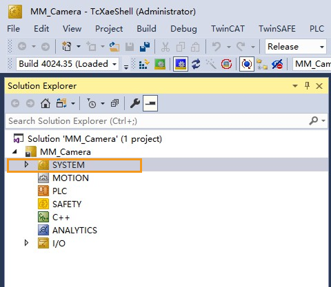
In the left navigation pane, double-click SYSTEM.
-
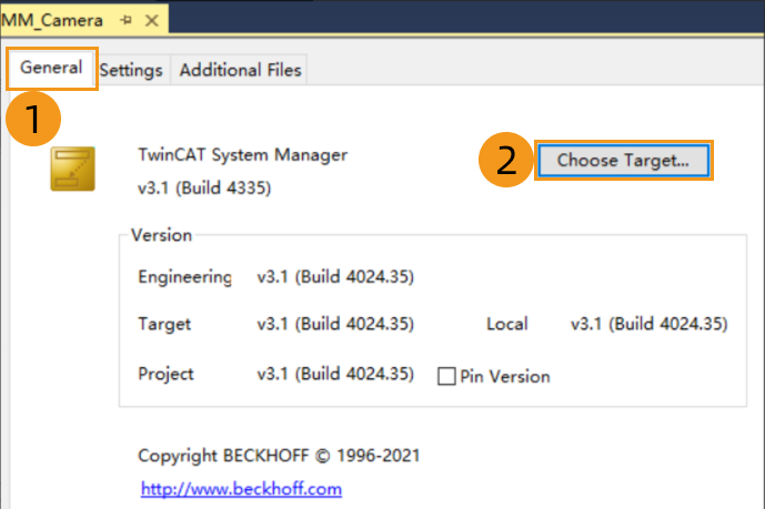
In the following window, select
-
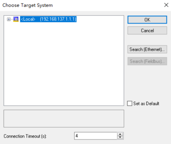
In the following window, select the controller to which you want to connect and click OK.
-
<Local> indicates a connection to the local virtual controller. In this example, <Local> is selected.
-
To connect to another controller, click Search (Ethernet)…. For detailed instructions, see Connecting to a Controller.
-
Add TF6281 (EtherNet/IP Scanner) Component
-
In the left navigation pane, double-click I/O, right-click Devices, and then select Add New Item.
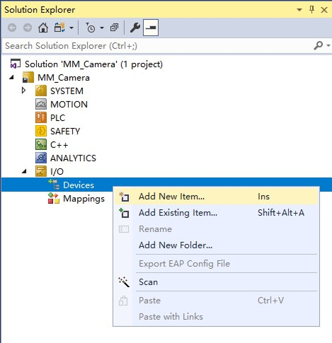
In the window that appears, set Type to EtherNet/IP Scanner, keep Name as the default Device 1, and then click OK.
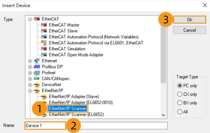
-
In the following window, click Settings, expand F800:0, double-click F800:21, change the IP address, and then click OK.
The IP address set here must be on the same subnet as the IPC. 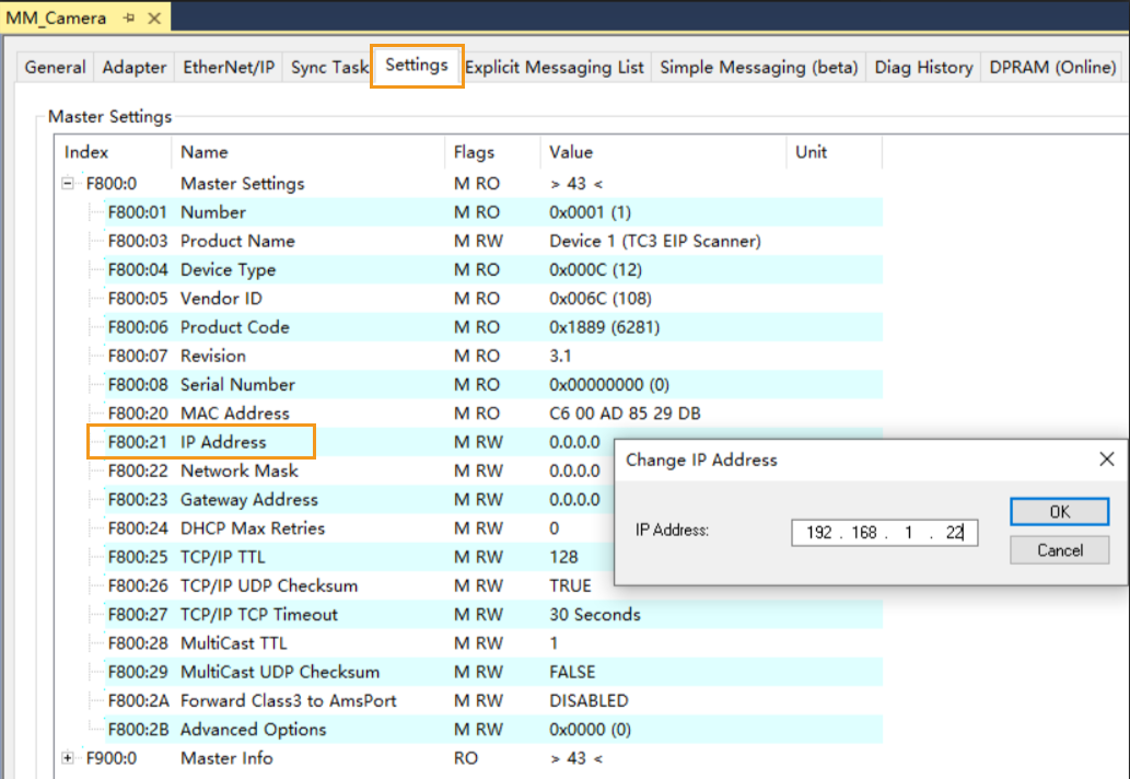
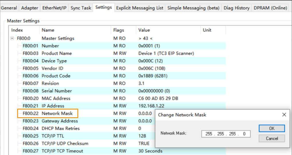
Double-click F800:22, change the subnet mask, and then click OK.
Install EDS File and Configure Communication
If you configure the software to set up the EtherNet/IP communication, click this line to view the detailed operations.
-
In the left navigation pane, right-click Device 1 (TC3 EIP Scanner) and select Import EDS File.
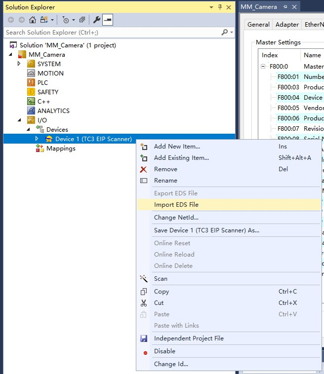
In the window that appears, select the Software EIP.eds file (which should be copied from the IPC in advance) and click Open.
The Software EIP.eds file can be found in the
Communication Component/Robot_Interface/EthernetIP/EDSpath in the directory where Mech-Vision and Mech-Viz are installed.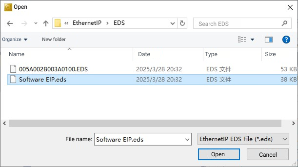
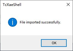
In the window that appears, click OK.
-
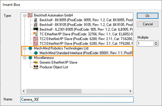
After the EDS file is installed, right-click Device 1 (TC3 EIP Scanner) and select Add New Item.
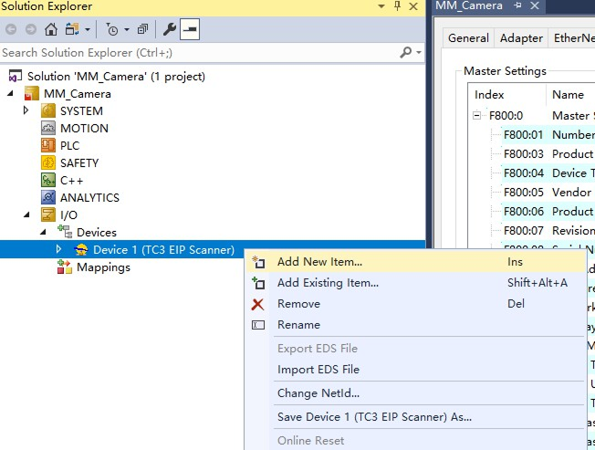
The following window pops up. Expand Mech-Mind Robotics Technologies Ltd. and select the Mech-Mind Standard Interface, enter a Name (you can specify a custom name, e.g., Camera_3D), and then click OK.
-
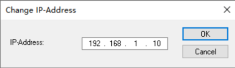
Right-click the newly added item (e.g., Camera_3D) and select Change IP Address.
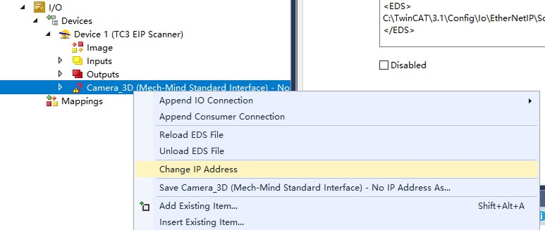
In the window that appears, change the IP address and then click OK.
The IP address here must be consistent with the IP address selected under*Network Adapters and IP Address* in the robot communication configuration settings in Mech-Vision.
-
Right-click the newly added item (e.g., Camera_3D) again, and select .
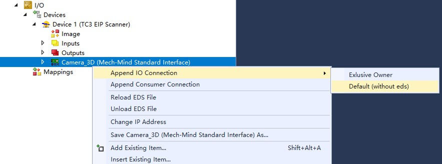
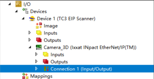
A connection variable, Connection 1 (Input/Output), is created, as shown in the figure below.

-
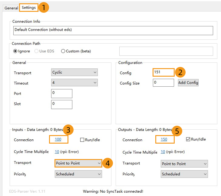
Double-click Connection 1 (Input/Output).
In the pop-up window, go to the Settings tab, set the parameters as shown in the figure, and then close the window.
-
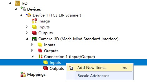
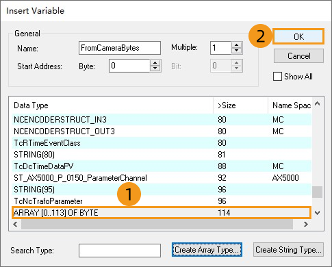
Expand Connection 1 (Input/Output), right-click Inputs, and select Add New Item.
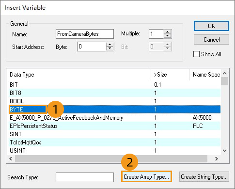
In the pop-up window, select BYTE and click Create Array Type.
In the next pop-up window, set the array index to 0 to 113 and click OK.
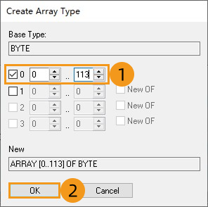
The created array will be displayed in the following window; click OK to confirm.
-
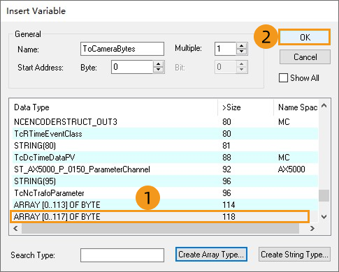
In the next window, right-click Outputs and select Add New Item.
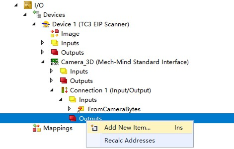
In the pop-up window, select BYTE and click Create Array Type.
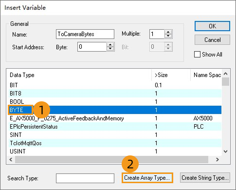
In the next pop-up window, set the array index to 0 to 117 and click OK.
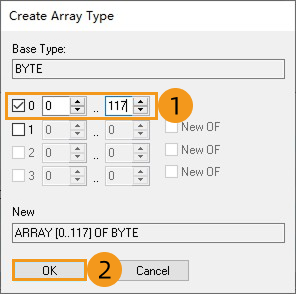
The created array will be displayed in the following window; click OK to confirm.
If you use a PCI-e card to set up the EtherNet/IP communication, click this line to view the detailed operations.
-
In the left navigation pane, right-click Device 1 (TC3 EIP Scanner) and select Import EDS File.
In the window that appears, select the 005A002B003A0100.EDS file (which should be copied from the IPC beforehand) and click Open.
The 005A002B003A0100.EDS file can be found in the
Communication Component/Robot_Interface/EthernetIP/EDSpath in the directory where Mech-Vision and Mech-Viz are installed.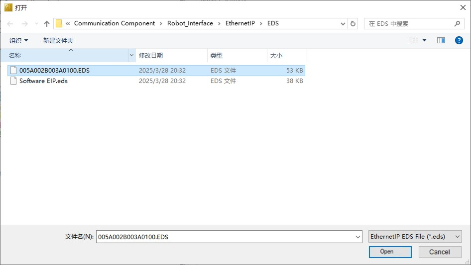
-
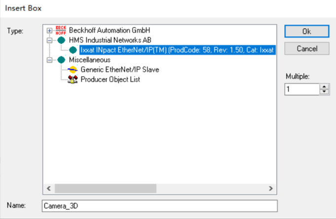
After the EDS file is installed, right-click Device 1 (TC3 EIP Scanner) and select Add New Item.
In the window that appears, expand HMS Industrial Networks AB, select Ixxat INpact EtherNet/IP (TM), enter a Name (you can specify a custom name, e.g., Camera_3D), and then click OK.
-
Right-click the newly added item (e.g., Camera_3D) and select Change IP Address.
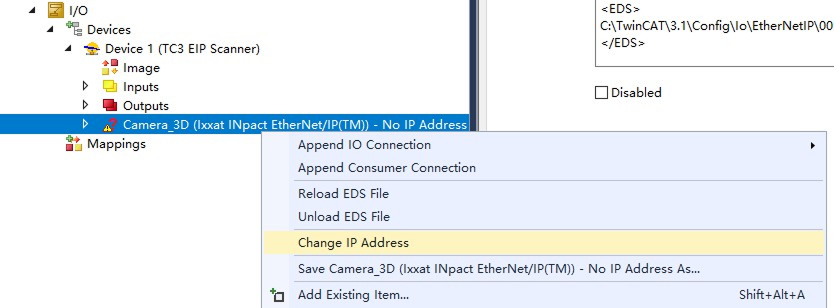
In the window that appears, change the IP address and then click OK.
The IP address here must be consistent with the IP address set in HMS IPconfig.
-
Right-click the newly added item (e.g., Camera_3D) again, and select .
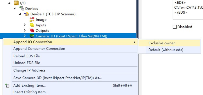
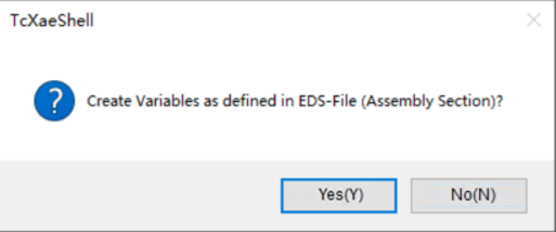
Click Yes in the pop-up window as shown below.
A connection variable, Connection 1 (Input/Output), is created, as shown in the figure below.
Import Example Programs
| Before you add the example program to a project already in use, it is recommended to import it to a new project and test it first. |
If you configure the software to set up the EtherNet/IP communication, click this line to view the detailed operations.
-
In the left navigation pane, right-click PLC and select Add Existing Item.
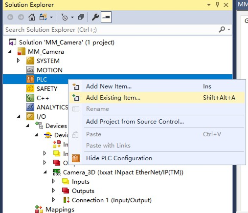
In the window that appears, select the MM_Camera.tpzip file (which should be copied from the IPC beforehand), and click Open.
The MM_Camera.tpzip file is located in the Communication Component/Robot_Interface/EthernetIP/Programming Samples/BECKHOFF PLC EthernetIPfolder under the installation path of Mech-Vision and Mech-Viz.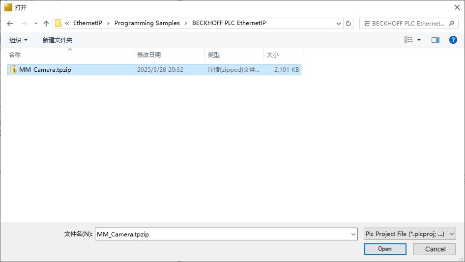
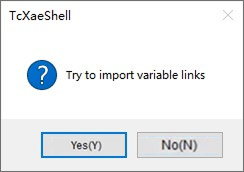
Click Yes in the pop-up window as shown below.
-
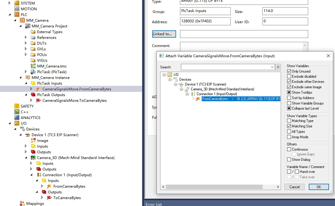
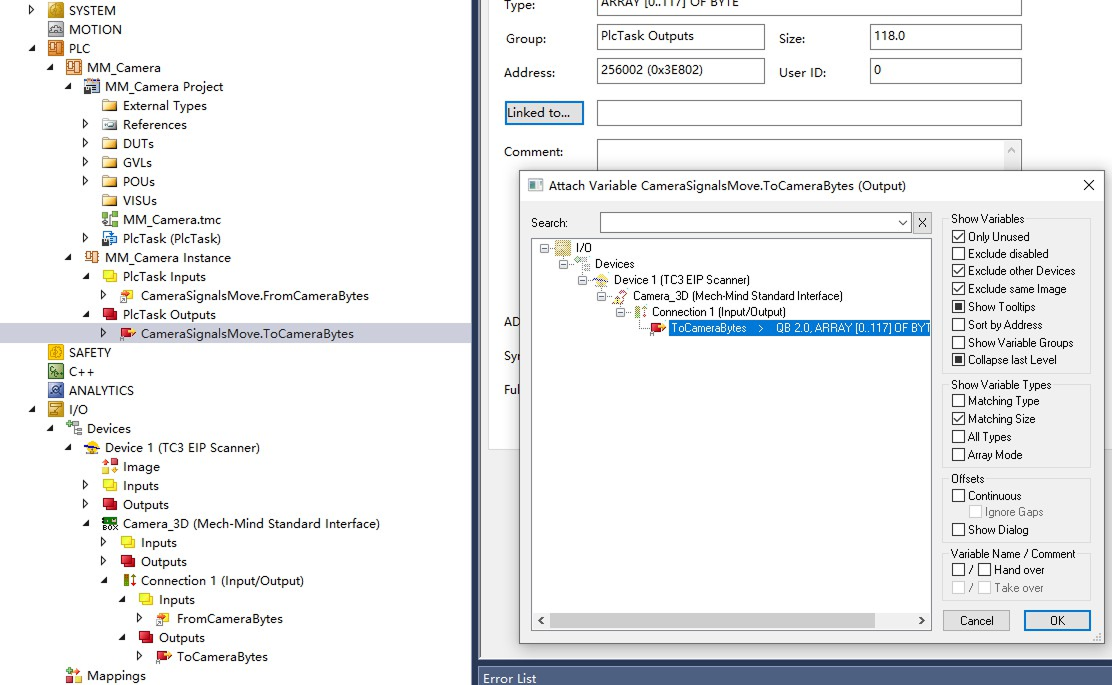
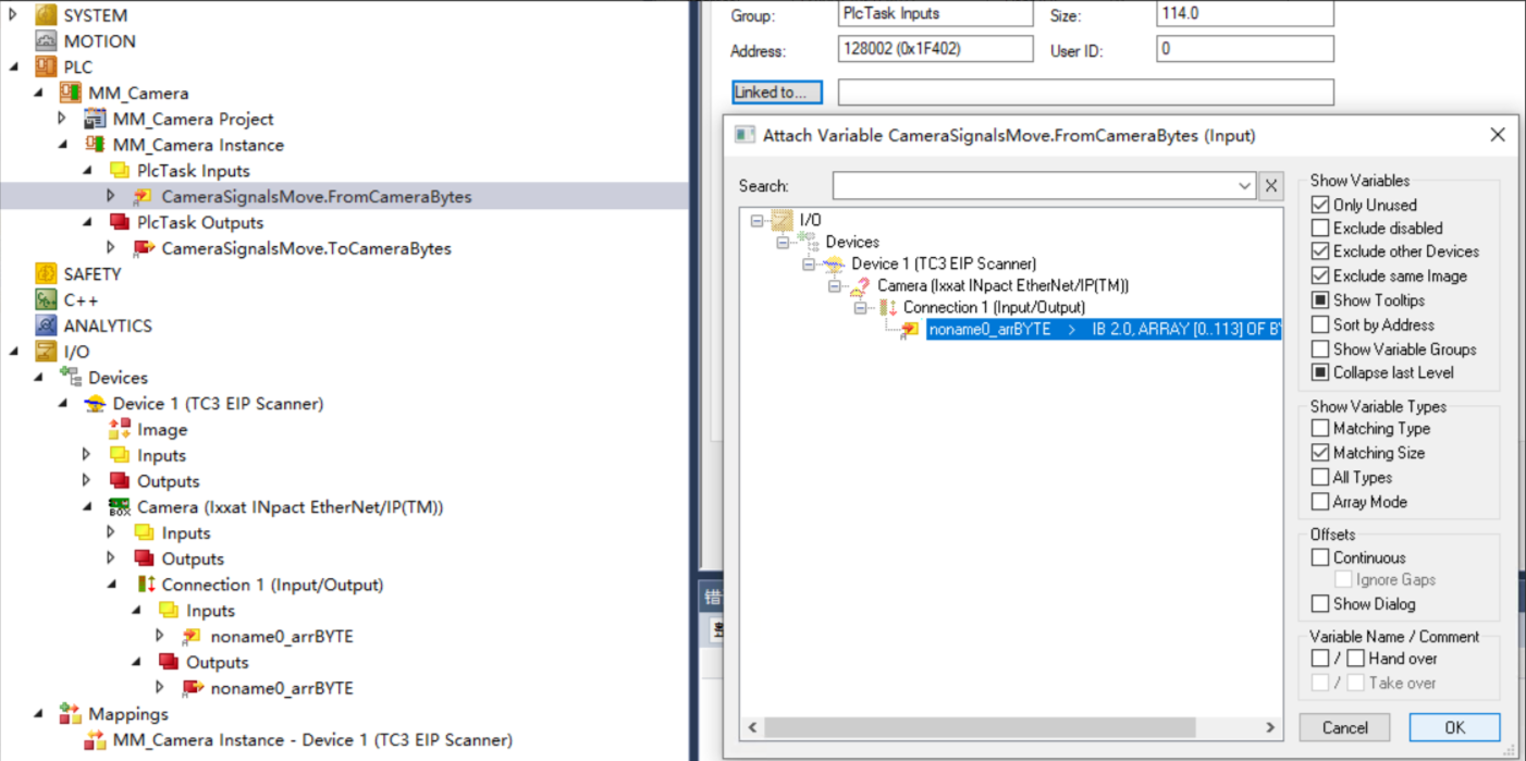
In the left navigation pane, expand PLC and ensure that both CameraSignalsMove.FromCameraBytes and CameraSignalsMove.ToCameraBytes are linked to Connection 1 (Input/Output).
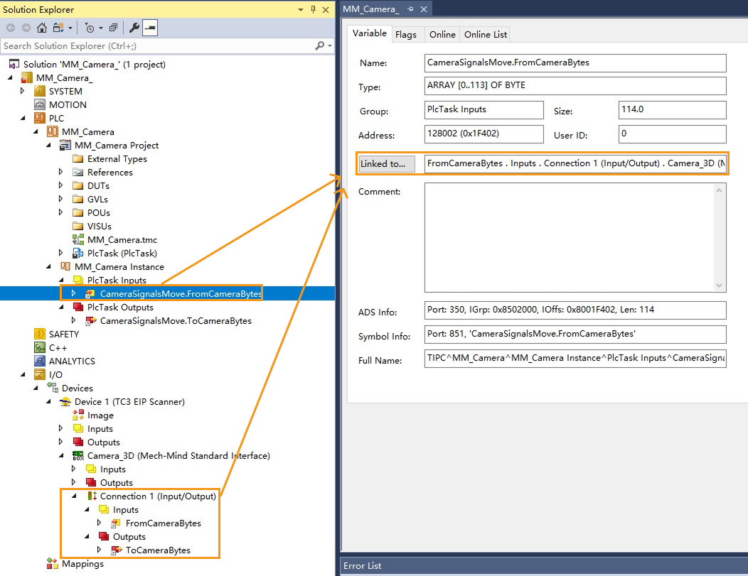
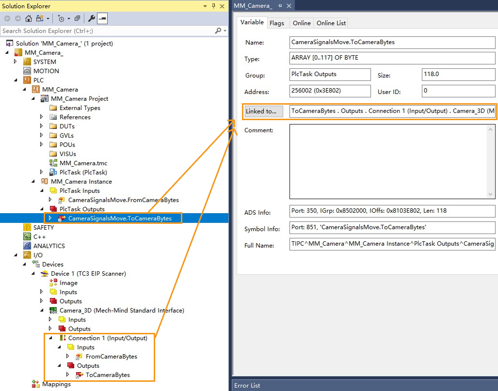
If the variables are not linked automatically, click Linked to…. In the window that appears, select the corresponding variables to link them manually. For example, the figure below shows that CameraSignalsMove.FromCameraBytes and CameraSignalsMove.ToCameraBytes are linked manually.
If you use a PCI-e card to set up the EtherNet/IP communication, click this line to view the detailed operations.
-
In the left navigation pane, right-click PLC and select Add Existing Item.
In the window that appears, select the MM_Camera.tpzip file (which should be copied from the IPC beforehand), and click Open.
The MM_Camera.tpzip file is located in the Communication Component/Robot_Interface/EthernetIP/Programming Samples/BECKHOFF PLC EthernetIPfolder under the installation path of Mech-Vision and Mech-Viz.
Click Yes in the pop-up window as shown below.
-
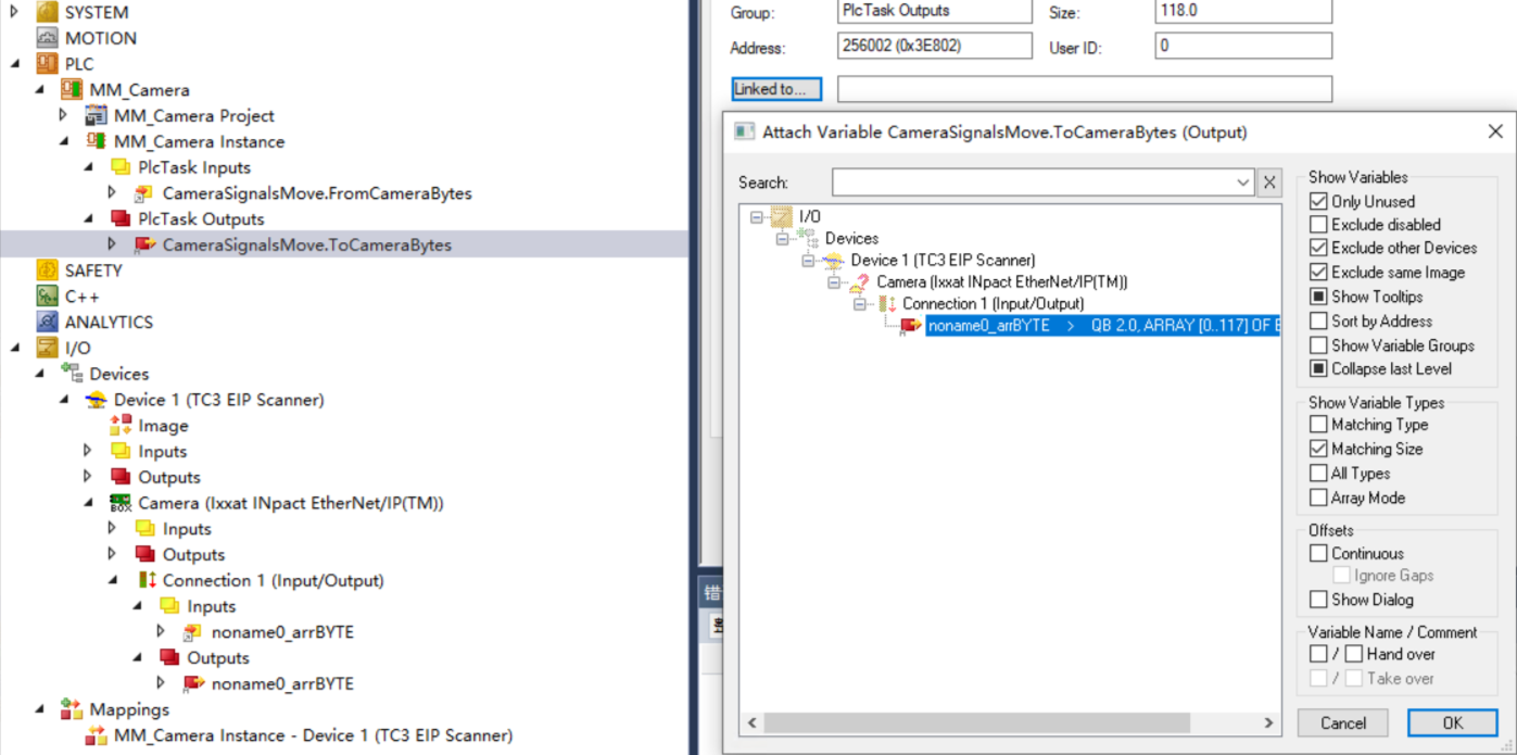
In the left navigation pane, expand PLC and ensure that both CameraSignalsMove.FromCameraBytes and CameraSignalsMove.ToCameraBytes are linked to Connection 1 (Input/Output).
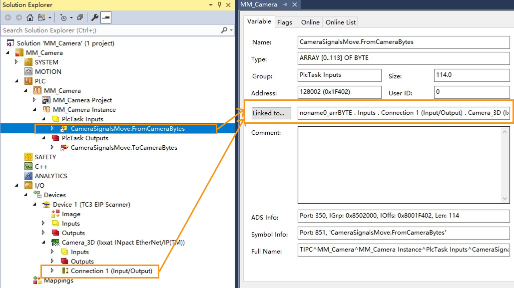
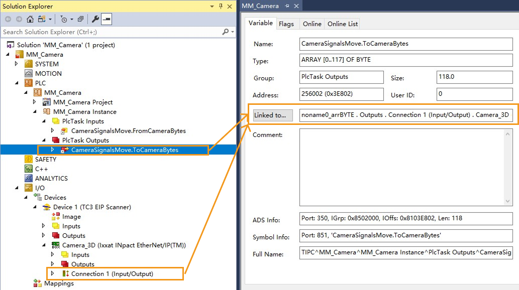
If the variables are not linked automatically, click Linked to…. In the window that appears, select the corresponding variables to link them manually. For example, the figure below shows that CameraSignalsMove.FromCameraBytes and CameraSignalsMove.ToCameraBytes are linked manually.
Activate Configuration and Log In to the PLC Program
-
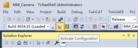
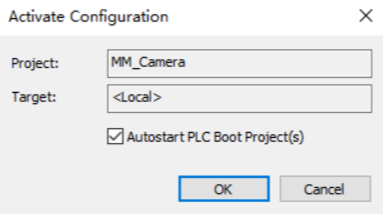
In the toolbar, click Activate Configuration.
In the window that appears, set Project and Target, and then click OK.
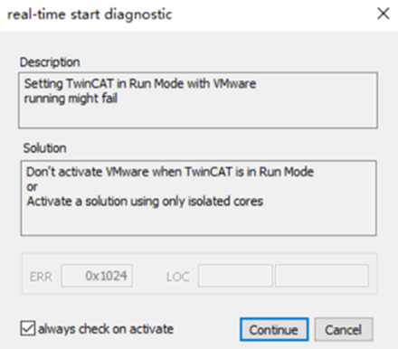
In the window that appears, click Continue.
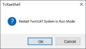
In the window that appears, click OK.
-
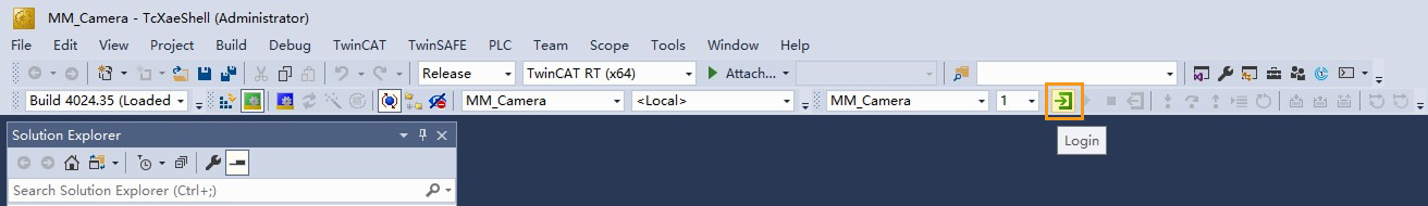
In the toolbar, click Login, and the PLC will enter Run mode.
Check Communication
-
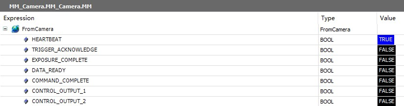
In the left navigation pane, double-click MM.
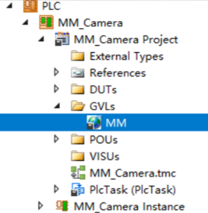
If the connection is successful, the FromCamera.HEARTBEAT signal in the MM variable table will continuously change.
-
The PLC is successfully connected if the following message is displayed in the Console tab of Mech-Vision Log panel: Connect to ETHERNET IP controller successfully. If you don’t see this log message, please check:
-
If the hardware is properly connected;
-
If the Interface Service has been enabled successfully in Mech-Vision;
-
If the TwinCAT 3 project configuration has been successfully activated;
-
If the PLC program has been successfully logged in and started.
-
Test with Mech-Vision/Mech-Viz Project
This section introduces how to use the example program FB to trigger the Mech-Vision project to obtain vision result and trigger the Mech-Viz project to obtain the planned path.
Prerequisites
-
Return to Mech-Vision and create a Mech-Vision project. Right-click the solution and select Autoload Solution. Projects in the solution are also autoloaded. Meanwhile, the project number will show up before each project name.
-
Create Mech-Viz project. Right-click the project name in Resources of Mech-Viz and select Autoload Project.
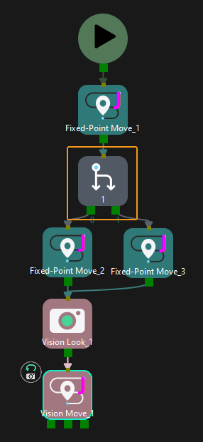
The Mech-Viz project used for testing should contain a “Branch by Msg” Step that has been renamed to 1 as shown below.
Get Vision Result from Mech-Vision
Configure Programs
-
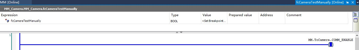
In the TwinCAT 3 software navigation pane, double-click fcCameraTestManually.
-
In section 1 of the fcCameraTestManually program, set the enable switch MM.ToCamera.COM_ENABLE to ON.
-
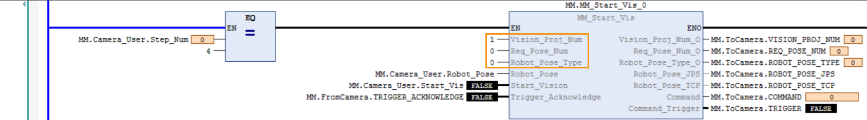
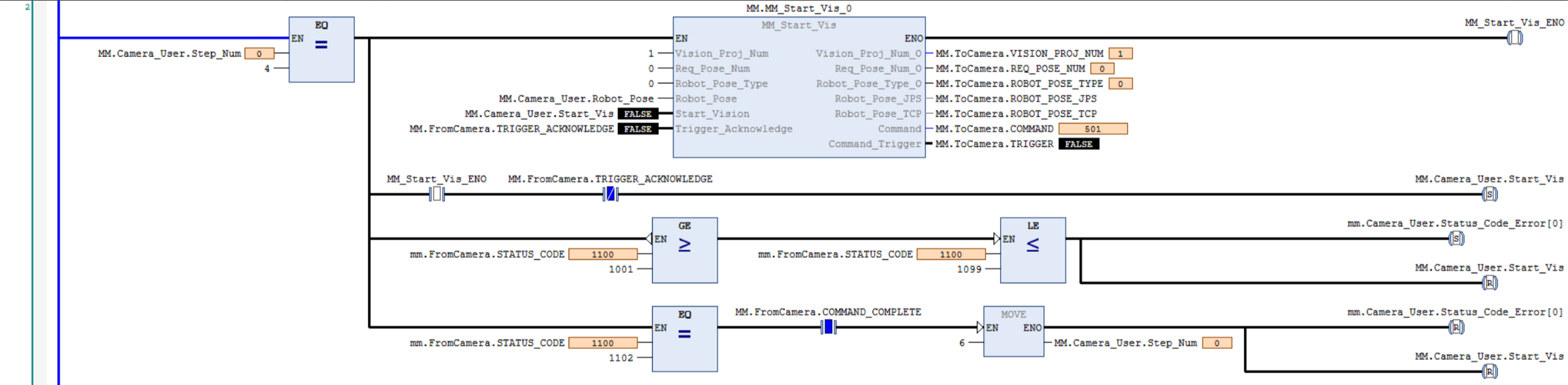
In section 4 of the fcCameraTestManually program, set the following values.
-
Set the port value of Vision_Proj_Num to 1, which means that Mech-Vision project No.1 will be run.
-
Set the value of Req_Pose_Num to 0, which means that all vision points will be expected to be returned by Mech-Vision.
-
Set the value of Robot_Pose_Type to 0. Then, the image-capturing pose does not need to be sent to the Mech-Vision project. For example, the image-capturing pose does not need to be sent when the camera is mounted in eye-to-hand mode.
-
Trigger Mech-Vision Project to Run
-
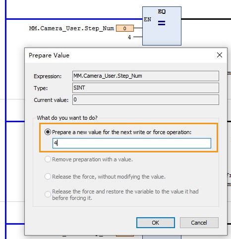
In section 4 of the fcCameraTestManually program, double-click the MM.Camera_User.Step_Num variable. In the input box that appears, enter 4 to set the next write value of MM.Camera_User.Step_Num to 4, and then click OK.
-
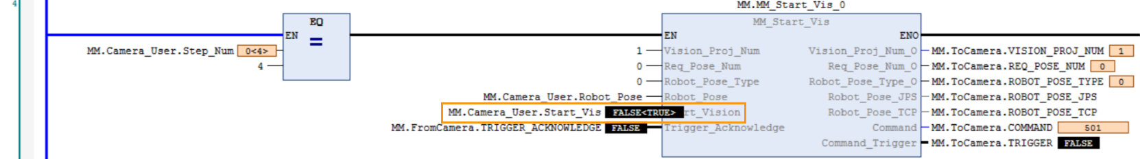
In section 4 of the fcCameraTestManually program, double-click the MM.Camera_User.Start_Vis variable and set it to TRUE.
-
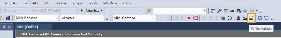
In the toolbar, click Write values to trigger the Mech-Vision project to run.
-
Double-click the MM.Camera_User.Start_Vis variable again and set it to FALSE.
-
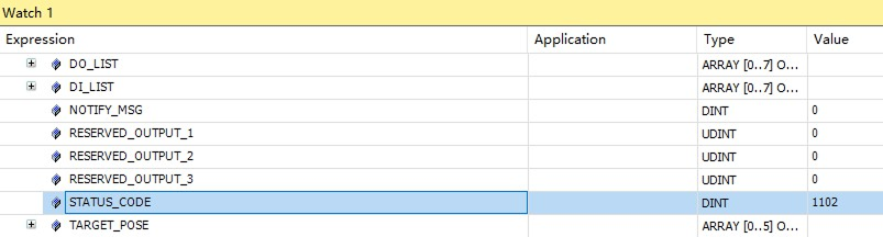
Check whether the returned value of STATUS_CODE is 1102.
-
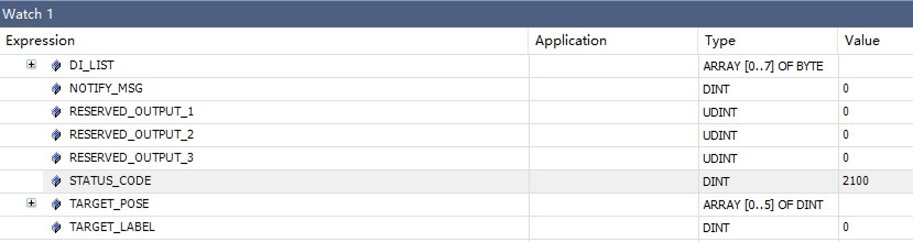
Click the Watch 1 tab in the status bar to log in to the watch window, and then add the MM.FromCamera variable.

-
Expand the MM.FromCamera variable and check the STATUS_CODE value.
-
If the STATUS_CODE value is 1102, it indicates that the Mech-Vision project has been successfully triggered to run.
-
If 10XX is displayed for STATUS_CODE and you want to troubleshoot the issue, see Status Codes and Troubleshooting.
-
-
Get Vision Result from Mech-Vision
-
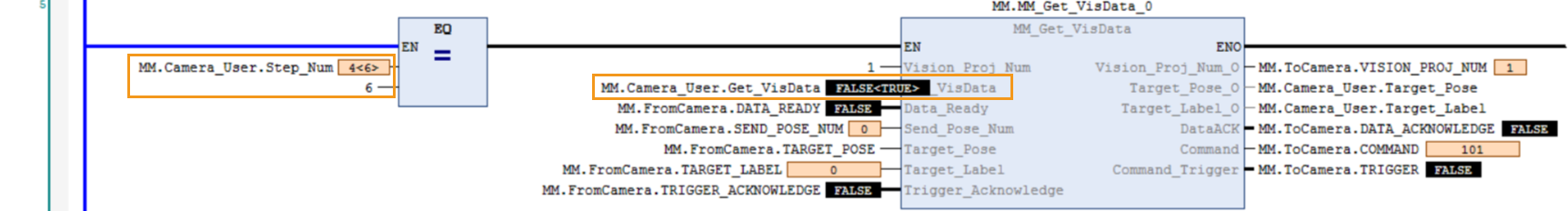
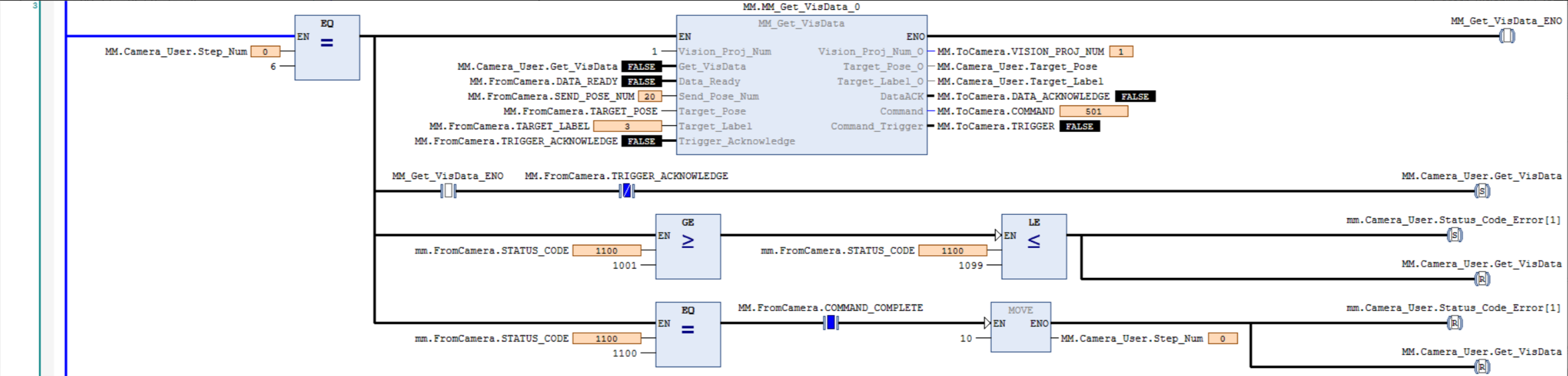
After STATUS_CODE returns 1102, go to section 5 of the fcCameraTestManually program and set the next write value of MM.Camera_User.Step_Num to 6.
Double-click the MM.Camera_User.Get_VisData variable and set it to TRUE to obtain the vision result.
-
In the toolbar, click Write values to obtain the vision result.
-
Double-click the MM.Camera_User.Get_VisData variable again and set it to FALSE.
-
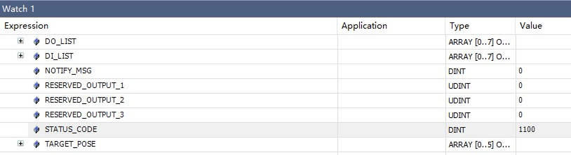
In the watch window, check the STATUS_CODE value.
-
If the STATUS_CODE value is 1100, it indicates that the vision result has been successfully obtained.
-
If 10XX is displayed for STATUS_CODE and you want to troubleshoot the issue, see Status Codes and Troubleshooting.
-
-
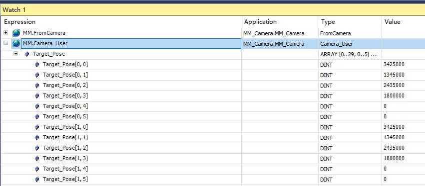
Check the values of Target_Pose.
-
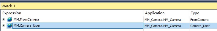
In the watch window, add the MM.Camera_User variable.
-
Expand the MM.Camera_User variable and check the Target_Pose values. In the figure, two sets of pose data sent by the vision system software are shown. Divide the pose data by 10000 to obtain the actual pose data.

-
Obtain Planned Path from Mech-Viz
Configure Programs
-
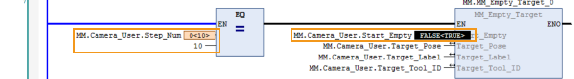
In section 7 of the fcCameraTestManually program, set the next write value of MM.Camera_User.Step_Num to 10.
Double-click the MM.Camera_User.Start_Empty variable and set it to TRUE to clear the previously obtained vision result.
-
In the toolbar, click Write values.
-
Double-click the MM.Camera_User.Start_Empty variable again and set it to FALSE.
-
Check the values of Target_Pose after the vision result is cleared in the watch window.
-
In section 12 of the fcCameraTestManually program, set the port values of Branch_Name and Branch_Exit_Port to 1, indicating that the Mech-Viz project will take exit port 1 of the Branch by Msg Step whose Step ID is 1.

-
In section 13 of the fcCameraTestManually program, set the port value of Request_Pose_Type to 1, indicating that the waypoints planned by Mech-Viz will be returned in the form of joint positions.
Trigger Mech-Viz Project to Run
-
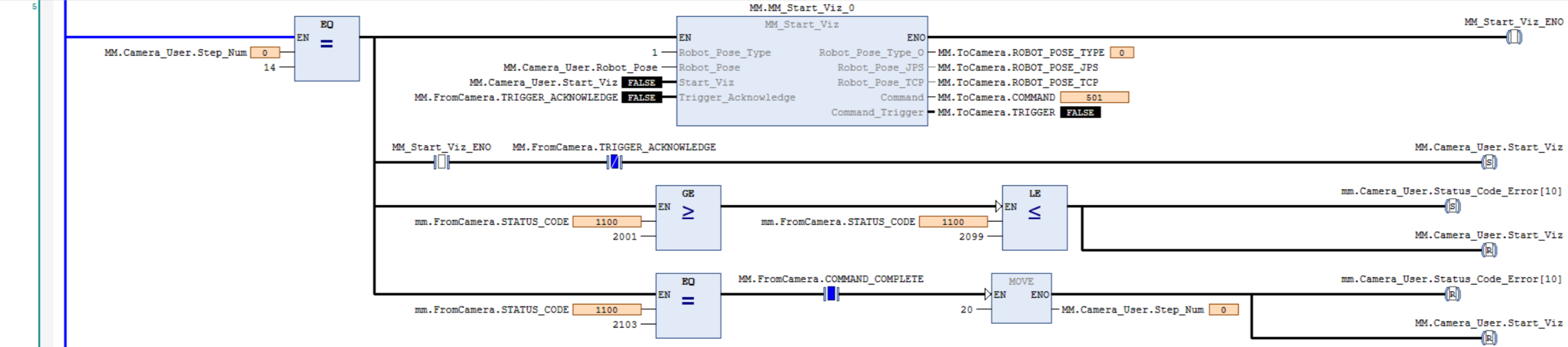
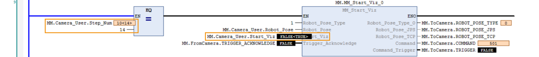
In section 9 of the fcCameraTestManually program, set the next write value of MM.Camera_User.Step_Num to 14.
Double-click the MM.Camera_User.Start_Viz variable and set it to TRUE to trigger the Mech-Viz project to run.
-
In the toolbar, click Write values to trigger the Mech-Viz project to run.
-
Double-click the MM.Camera_User.Start_Viz variable again and set it to FALSE.
-
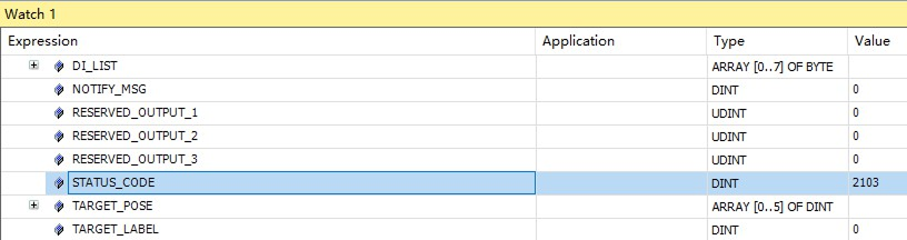
In the watch window, check the STATUS_CODE value.
-
If the STATUS_CODE value is 2103, it indicates that the Mech-Viz project has been successfully triggered to run.
-
If 20XX is displayed for STATUS_CODE and you want to troubleshoot the issue, see Status Codes and Troubleshooting.
-
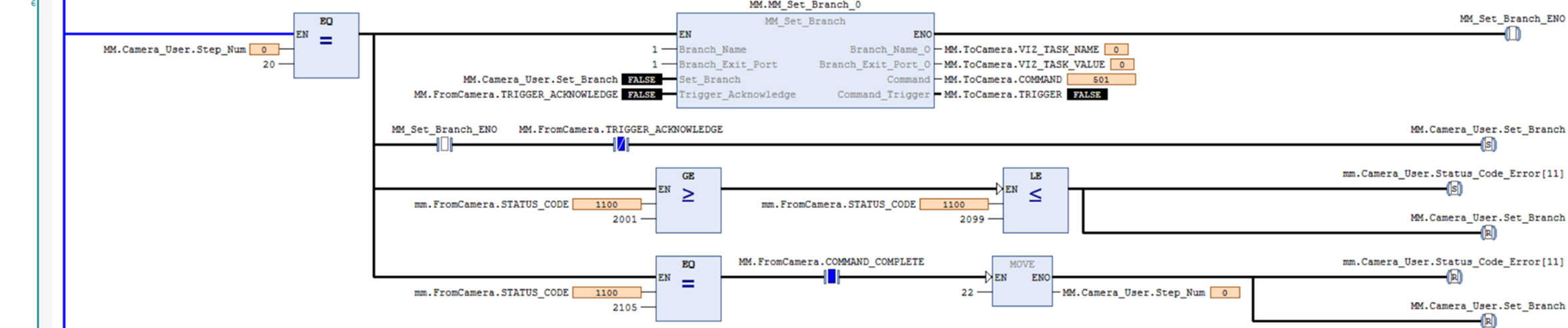
Set the Exit Port for the Branch by Msg Step in Mech-Viz
-
In section 12 of the fcCameraTestManually program, set the next write value of MM.Camera_User.Step_Num to 20.
Double-click the MM.Camera_User.Set_Branch variable and set it to TRUE to set the exit port of the Branch by Msg Step.

-
In the toolbar, click Write values to set the exit port of the Branch by Msg Step.
-
Double-click the MM.Camera_User.Set_Branch variable again and set it to FALSE.
-
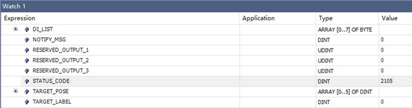
In the watch window, check the STATUS_CODE value.
-
If the STATUS_CODE value is 2105, it indicates that the exit port of the Branch by Msg Step has been successfully set.
-
If 20XX is displayed for STATUS_CODE and you want to troubleshoot the issue, see Status Codes and Troubleshooting.
-
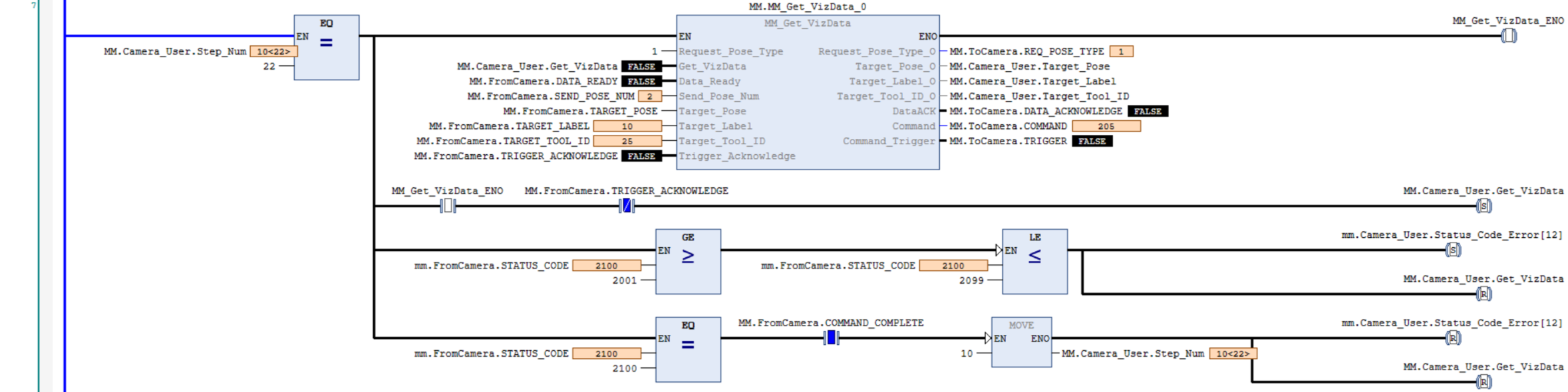
Obtain Planned Path from Mech-Viz
-
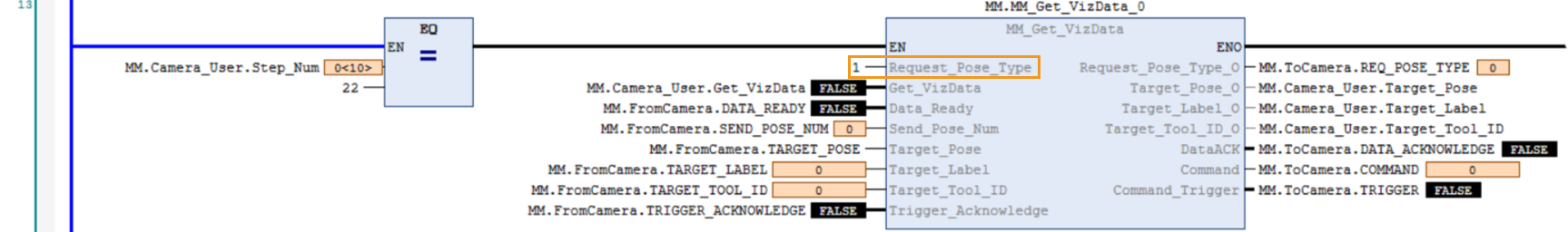
In section 13 of the fcCameraTestManually program, set the next write value of MM.Camera_User.Step_Num to 22.
Double-click the MM.Camera_User.Get_VizData variable and set it to TRUE to obtain the planned path.
Check the value of MM.FromCamera.SEND_POSE_NUM later. 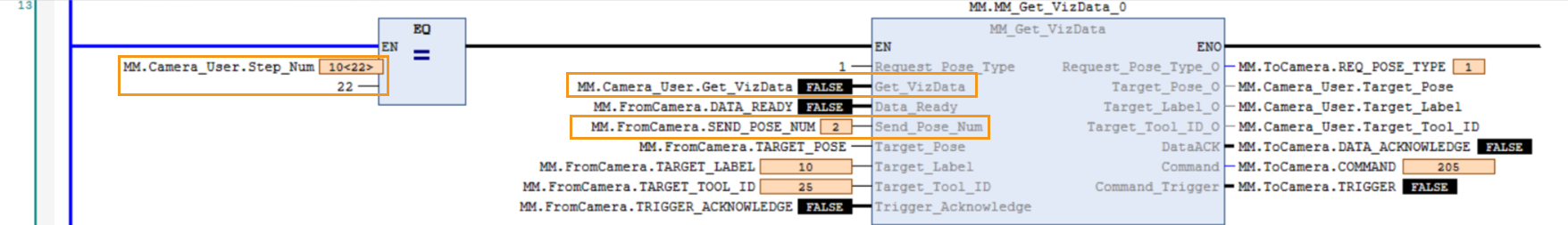
-
In the toolbar, click Write values to obtain the planned path.
-
Double-click the MM.Camera_User.Get_VizData variable again and set it to FALSE.
-
The MM.FromCamera.SEND_POSE_NUM value is 2, indicating that two sets of joint position data were obtained in this example.
-
In the watch window, check the STATUS_CODE value.
-
If the STATUS_CODE value is 2100, it indicates that the planned path has been successfully obtained.
-
If 20XX is displayed for STATUS_CODE and you want to troubleshoot the issue, see Status Codes and Troubleshooting.
-
-
Check the returned values of Target_Pose in the watch window. Divide the returned values by 10000 to obtain the actual pose data.