Example Program 19: MM_S19_Vis_PlanAllVision
Program Introduction
Description |
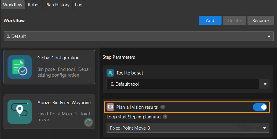
The robot triggers the Mech-Vision project to run. Then, the robot uses for loops to obtain all planned paths and perform picking and placing. In this example, once the camera captures an image, Mech-Vision will plan picking paths for all vision results. This program is applicable to scenarios where one image is used to perform picking for multiple times. |
||
File path |
You can navigate to the installation directory of Mech-Vision and Mech-Viz and find the file by using the |
||
Project |
Mech-Vision project
|
||
Prerequisites |
|
| This example program is provided for reference only. Before using the program, please modify the program according to the actual scenario. |
Program Description
This part describes the MM_S19_Vis_PlanAllVision example program.
| The only difference between the MM_S19_Vis_PlanAllVision example program and the MM_S3_Vis_Path example program is that MM_S19_Vis_PlanAllVision can use for loops to obtain all planned paths and perform picking and placing (this code of this feature is bolded). As such, only the feature of using for loops to obtain all planned paths and perform picking and placing is described in the following part. For information about the parts of MM_S19_Vis_PlanAllVision that are consistent with those of MM_S3_Vis_Path, see Example Program: MM_S3_Vis_Path. |
1: !-------------------------------- ;
2: !FUNCTION: trigger Mech-Vision ;
3: !project, plan all vision results ;
4: !and get all planned paths ;
5: !Mech-Mind, 2023-12-25 ;
6: !-------------------------------- ;
7: ;
8: !set current uframe NO. to 0 ;
9: UFRAME_NUM=0 ;
10: !set current tool NO. to 1 ;
11: UTOOL_NUM=1 ;
12: !move to robot home position ;
13:J P[1] 100% FINE ;
14: !initialize communication ;
15: !parameters(initialization is ;
16: !required only once) ;
17: CALL MM_INIT_SKT('8','127.0.0.1',30000,5) ;
18: LBL[1:recap] ;
19: !move to image-capturing position ;
20:L P[2] 1000mm/sec FINE ;
21: !trigger NO.1 Mech-Vision project ;
22: CALL MM_START_VIS(1,0,2,10,53) ;
23: !check whether vision project has ;
24: !been triggered successfully ;
25: IF (R[53]<>1102),JMP LBL[99] ;
26: !get planned path from NO.1 ;
27: !Mech-Vision project; 2nd ;
28: !argument (1) means getting pose ;
29: !in JPs ;
30: CALL MM_GET_VISP(1,1,51,52,53) ;
31: !check whether planned path has ;
32: !been got from Mech-Vision ;
33: !successfully ;
34: IF R[53]<>1103,JMP LBL[99] ;
35: !save all waypoint data to local ;
36: !variables using for-loop, a ;
37: !maximum of 50 points are support ;
38: !supported ;
39: FOR R[10]=1 TO R[51] ;
40: R[11]=59+R[10] ;
41: R[12]=69+R[10] ;
42: R[13]=99+R[10] ;
43: CALL MM_GET_JPS(R[10],R[11],R[12],R[13]) ;
44: ENDFOR ;
45: !parse pick cycle count, here ;
46: !suppose 5 points per planned ;
47: !path ;
48: R[30]=R[51] DIV 5 ;
49: R[29]=R[51] MOD 5 ;
50: !check if parsed data is valid; ;
51: !if not, retry to get planned ;
52: !path or add some error handling ;
53: !logic ;
54: IF R[30]<1) OR (R[29]<>0 THEN ;
55: PAUSE ;
56: JMP LBL[1] ;
57: ENDIF ;
58: !repeatedly run pick-and-place ;
59: !cycle using for-loop ;
60: FOR R[10]=1 TO R[30] ;
61: R[20]=R[10]-1 ;
62: R[21]=R[20]*5 ;
63: R[31]=60+R[21] ;
64: R[32]=61+R[21] ;
65: R[33]=62+R[21] ;
66: R[34]=63+R[21] ;
67: R[35]=64+R[21] ;
68: !follow the planned path to pick ;
69:J PR[R[31]] 50% CNT100 ;
70:J PR[R[32]] 50% FINE ;
71:J PR[R[33]] 10% FINE ;
72: !add object grasping logic here, ;
73: !such as "DO[1]=ON" ;
74: PAUSE ;
75:J PR[R[34]] 50% FINE ;
76:J PR[R[35]] 50% CNT100 ;
77: !move to intermediate waypoint ;
78: !of placing ;
79:J P[3] 50% CNT100 ;
80: !move to approach waypoint ;
81: !of placing ;
82:L P[4] 1000mm/sec FINE Tool_Offset,PR[2] ;
83: !move to placing waypoint ;
84:L P[4] 300mm/sec FINE ;
85: !add object releasing logic here, ;
86: !such as "DO[1]=OFF" ;
87: PAUSE ;
88: !move to departure waypoint ;
89: !of placing ;
90:L P[4] 1000mm/sec FINE Tool_Offset,PR[2] ;
91: !move to intermediate waypoint ;
92: !of placing ;
93:J P[3] 50% CNT100 ;
94: ENDFOR ;
95: !finish pick-and-place cycle, and ;
96: !jump back to camera capturing ;
97: JMP LBL[1] ;
98: END ;
99: ;
100: LBL[99:vision error] ;
101: !add error handling logic here ;
102: !according to different ;
103: !error codes ;
104: !e.g.: status=1003 means no ;
105: !point cloud in ROI ;
106: !e.g.: status=1002 means no ;
107: !vision results ;
108: !e.g.: mm_status=3099 means ;
109: !failed to open socket ;
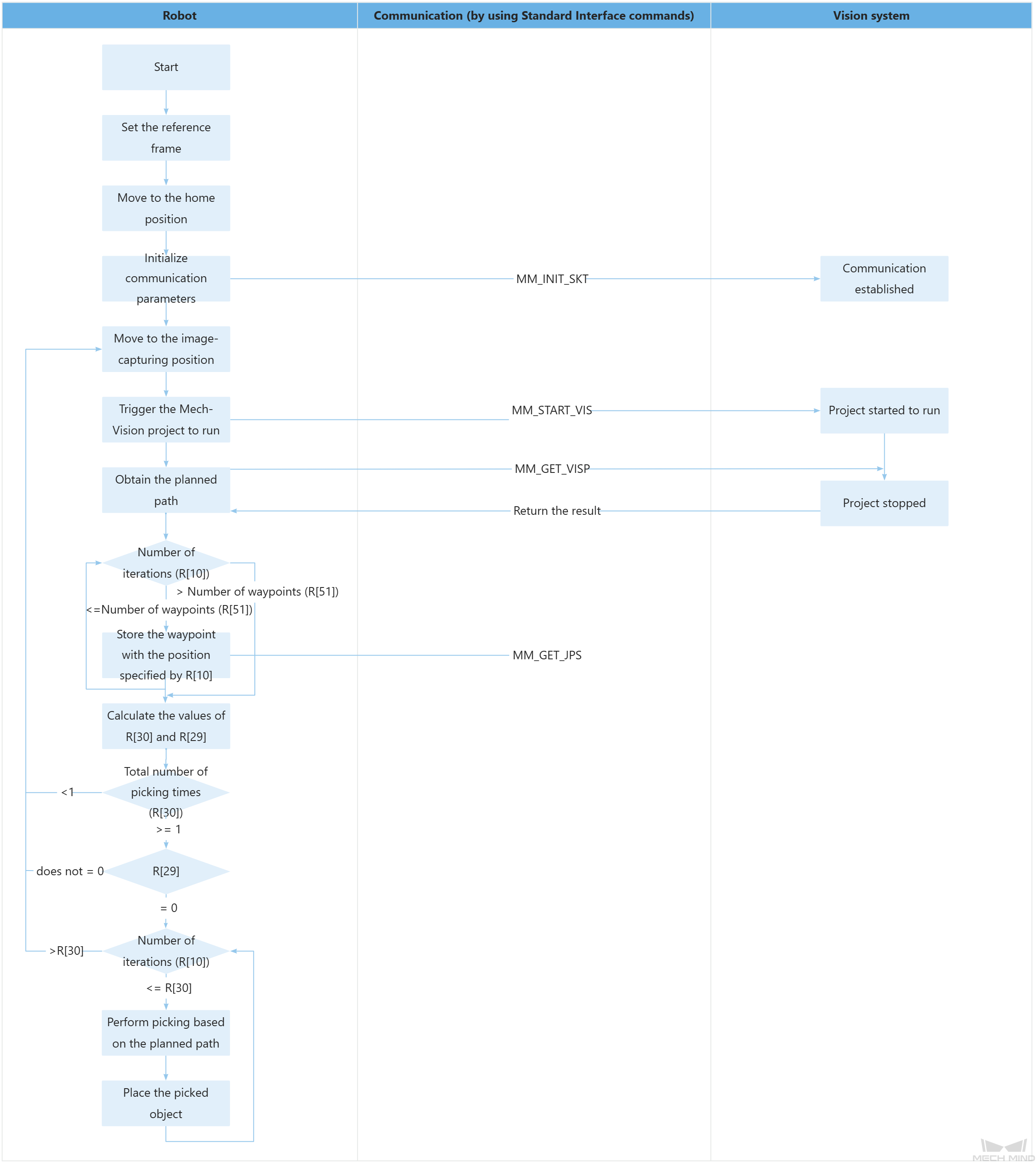
110: PAUSE ;The workflow corresponding to the above example program code is shown in the figure below.
The table below describes the feature of using for loops to obtain all planned paths and perform picking and placing. You can click the hyperlink to the command name to view its detailed description.
| Feature | Code and description |
|---|---|
Store the planned path by looping |
|
Calculate the values for R[30] and R[29] |
This example assumes that each planned picking path consists of 5 waypoints. “R[51] DIV 5” indicates the quotient when the value of R[51] is divided by 5, and “R[51] MOD 5” indicates the remainder when the value of R[51] is divided by 5. R[30] indicates the total number of picking times. If R[29] is not set to 0, the planned number of picking waypoints is less than 5 (i.e., an error has occurred during path planning and a re-planning operation is needed). |
Determine whether an error has occurred during path planning |
If the number of picking times (R[30]) is less than 1 or the value of R[29] is not 0, an error has occurred during path planning. You need to add processing code here, such as the code to restart the Mech-Vision project and then obtain the planned path. |
Perform picking and placing by looping |
The above code indicates that in the for loop, the robot moves to the 5 waypoints planned each time to complete the picking operation and then performs the placing operation. R[10] is used to control the number of iterations in the loop (i.e., the value of R[10] starts from 1 and increments by 1 after each loop iteration until it exceeds the value of R[30], at which point the loop ends. Each time the value of R[10] increases by 1, the value of R[21] is incremented by 5. The range 60+R[21] to 64+R[21] (i.e., R[31] to R[35]) corresponds to the IDs of the registers where the 5 waypoints of each planned path will be stored. |