Master-Control Communication Setup
This guide shows you how to set up Master-Control communication with a Comau robot.
Preparation
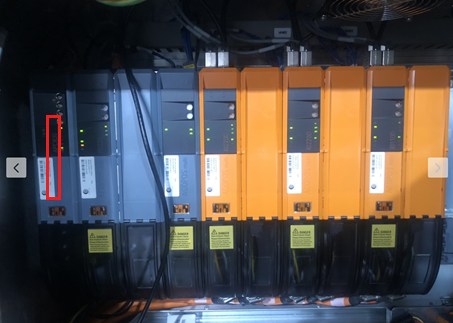
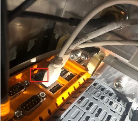
Connect the Hardware
Plug the Ethernet cable of the IPC into the RJ45 port on the top of the first module.
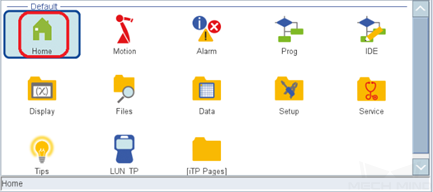
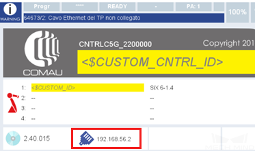
Check the IP Address
Press the menu key on the teach pendant to enter the main interface. Select Home to view the robot’s IP address.
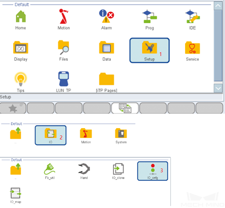
Configure and Map IO
-
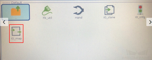
Select on the interface.
-
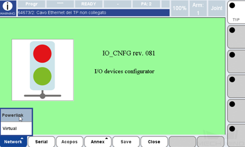
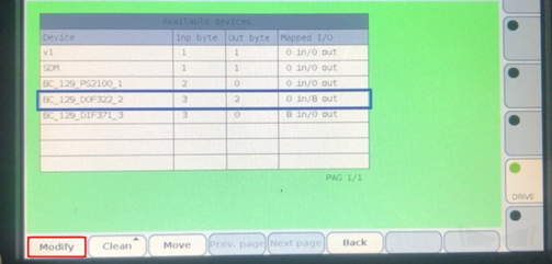
Select . The list of I/O devices is displayed on this interface.
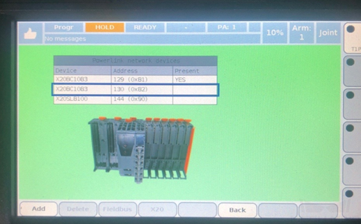
After making sure that the device is configured, you may start configuring the signal mapping.
-
Select on the teach pendant.
-
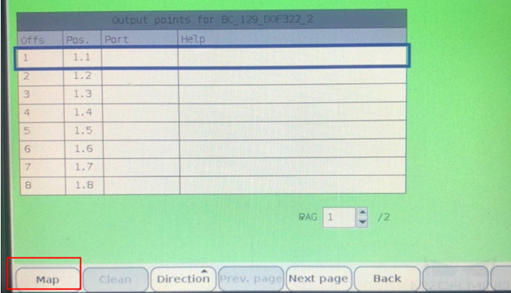
Press Devices, and then select the IO device which is configured. Press Modify. The output signal is taken as an example in the image below.


-
Select the first blank frame 1.1, and then press Map.
-
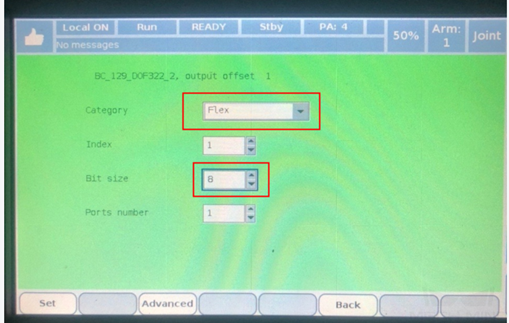
Configure the parameters as in the image below, and then press Set.
-
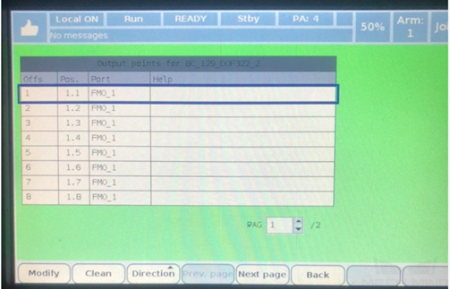
The image below indicates that the output signals are successfully configured. The 8 digits of the FMO_1 variable correspond to the 8 output signals on the IO device.
The following steps show you how to configure the input signals. Click Back.
-
Select the IO device whose input signals are configured. You may configure the input and output signals on the same device or different devices. Press Modify.
-
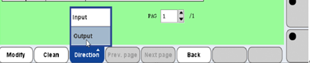
Select .
-
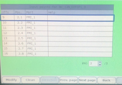
Repeat steps 3 to 5 to configure the input signals. After configuration, the interface is shown below.
-
Back, and the image below, which indicates that the input signals are successfully configured, will appear. The 8 digits of the FMI_1 variable correspond to the 8 input signals on the IO device.

-
Select Save. Now, the IO signals are configured. Please restart the robot.
For now, the IO of the Comau robot that Mech-Mind has adapted to uses two block variables, fmi[1] and fmo[1], each containing 8 signals.
Load the Program Files to the Robot
-
Go to
Communication Component/Robot_Server/Robot_FullControl/comaufrom the installation directory of Mech-Vision & Mech-Viz. Copy all files in the folder and paste them to your USB flash disk. -
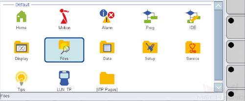
Plug the USB flash disk into the teach pendant, and select Files.
-
Select . Select your USB flash disk and find the files to be loaded.
+ . Select a file, and then select .
+ . Select , and then select the UD-USR folder.
+ image::comau/burn_files_4.png[align="center",width=680]
+ . Enter the usr folder, and select .
+ . Paste the remaining files to the usr folder.
-
Select a PDL file in the usr folder, and then select .
+ . A COD file with the same filename with be generated after the translation.
+ image::comau/burn_files_7.png[align="center",width=680]
Now, the loading is finished.
Test Master-Control Communication
Run the Program
-
Press
Menuand then press prog on the menu page.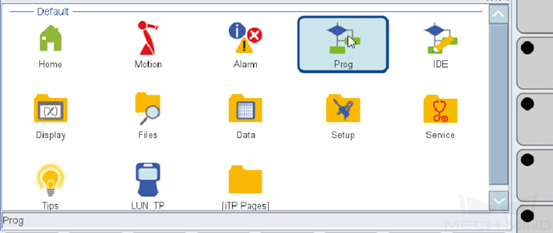
-
Select .
+ . Select a COD file and press OK.
+ . Upload the remaining COD files.
+ NOTE: The status and line number of the programs in the image above are normal.
+ . Complete the steps in the image below.
+ image::comau/run_program_5.png[align="center",width=680]
+ . Then, the memory interface is as follows. Note the status and line number.
+ image::comau/run_program_6.png[align="center",width=680]
Create a Mech-Viz Project
-
Open Mech-Viz, press Ctrl + N on the keyboard to create a new project. Select the robot model corresponding to your real robot brand and model on the interface as shown below.

-
Press Ctrl + S and create or select a folder to save the project.
-
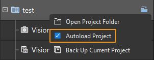
Right-click the project name in the left panel in Mech-Viz and select Autoload Project.
Connect to the Robot
-
Click Master-Control Robot on the toolbar of Mech-Viz.
-
Input the IP address of the real robot in Robot IP address (the IP address in the picture is only an example). Click Connect the robot.

If Mech-Viz successfully connects the real robot, the current status will change to Connected. Meanwhile, the icon in the toolbar will turn from blue to green.
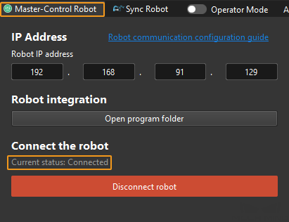
If the connection fails, please double-check the robot IP address.
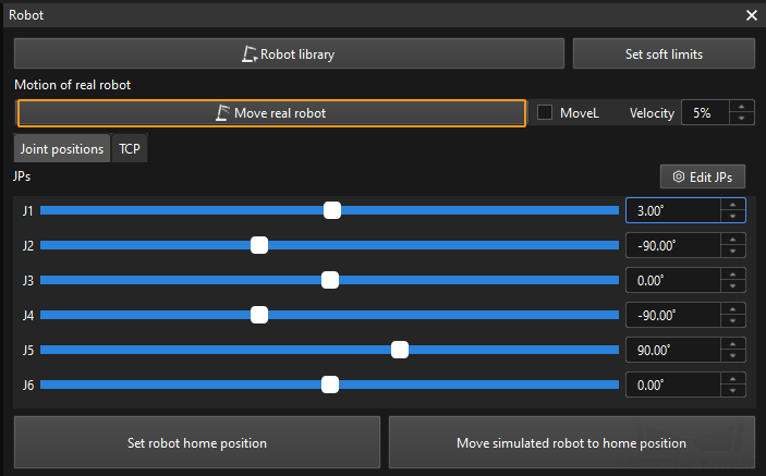
Move the Robot
-
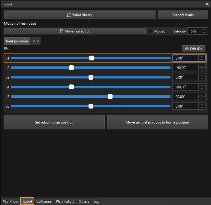
In the toolbar of Mech-Viz, change the “Vel.” (velocity) and “Acc.” (acceleration) parameters to 5%.

-
Click Sync Robot in the toolbar, and you can synchronize the poses of the simulated robot in the 3D simulation space with the poses of the real robot. Then click Sync Robot again to unselect it.

-
In the Robot tab, slightly adjust the value of “J1”, for example, from 0˚ to 3˚. This operation will move the simulated robot.
-
Click Move real robot and check if the real robot has moved. If the real robot has reached the JPs set for the simulated robot, the master-control communication is working.
When moving the robot, please ensure the safety of personnel. In the case of an emergency, press the emergency stop button on the teach pendant!