Set up Standard Interface Communication with ESTUN
This guide shows how to load the Standard Interface program files to an ESTUN robot, and set up the Standard Interface communication between Mech-Mind Vision System and the robot.
| In this section, you will load the robot Standard Interface program and the configuration files to the robot system to establish the Standard Interface communication between the vision system and the robot. |
Check Controller and Software Compatibility
|
The models and versions listed below are tested and can be used. For other models and versions, you may refer to this guide for operation. If any issues occur, please contact Mech-Mind Technical Support. |
-
System version: RCS2 V1.32, V1.33, V1.36.06.
-
Controller version: V1.32, V1.33, V1.36.06.
It is recommended to use the suggested system version. The following versions may not be able to communicate properly with the vision system:
Versions that are currently not supported: 1.34, 1.35, and 1.36.01 to 1.36.05.
Versions for which compatibility is not confirmed: 1.36.06 and above
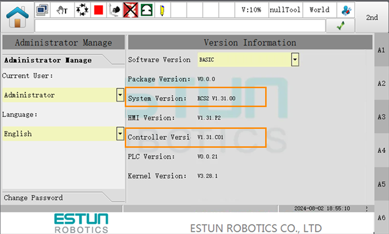
You can check the version information by tapping User Login on the main screen of the teach pendant.
Set up the Network Connection
Connect the Hardware
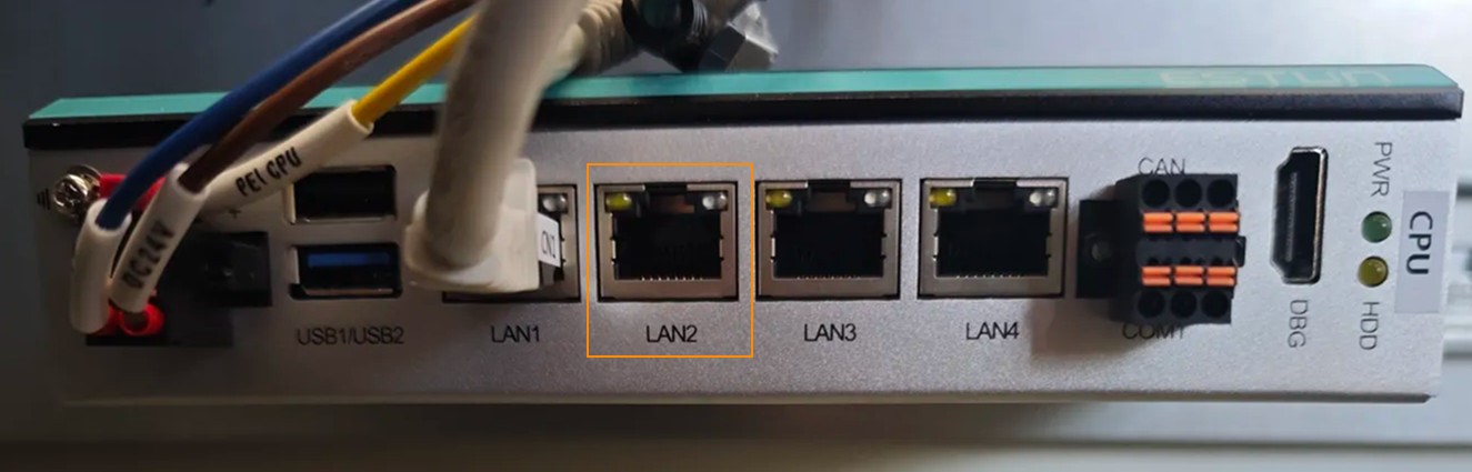
Plug one end of the Ethernet cable into the network port of the IPC and the other end into the LAN2 or LAN3 port on the controller.
|
Set the IP Address
-
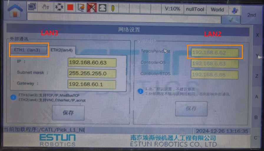
On the teach pendant, enter teach mode, then tap User Login on the main screen. In the Current User dropdown list, select Administrator and enter the password (default: 000000) to switch to administrator mode.
-
After logging in as an administrator, go back to the main screen and navigate to . Check or modify the IP address for the selected network port.
-
On the IPC, set the IP address to ensure it is within the same subnet as the controller. Use the ping command to test and confirm that the network connection is successful.
Set up Robot Communication Configuration
-
Open Mech-Vision. You may enter different interfaces. Create a new solution according to the instructions below.
-
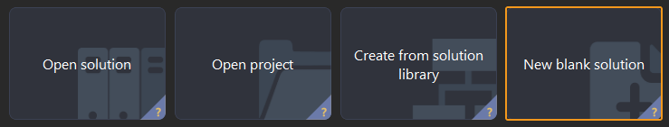
If you have entered the Welcome interface, click New blank solution.
-
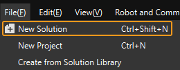
If you have entered the main interface, click on the menu bar.
-
-
Click Robot Communication Configuration on the toolbar of Mech-Vision.
-
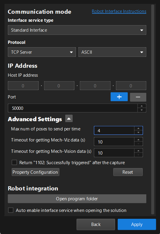
In the Robot Communication Configuration window, complete the following configurations.
-
Click the Select robot drop-down menu, and select Listed robot. Click Select robot model, and select the robot model that you use. Then, click Next.
-
In the Communication mode section, select Standard Interface for Interface service type, TCP Server for Protocol, and ASCII for the protocol format.
-
In the Advanced Settings section, set Max num of poses to send per time to 4.
-
Under Robot integration, click Open program folder.
-
If you want to manually load program files, you must perform this step. Otherwise, skip this step.
-
The files needed for subsequent loading will be copied from this folder. Do not close this folder.
-
-
(Optional) Select Auto enable interface service when opening the solution.
-
Click Apply.
-
-
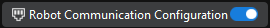
On the main interface of Mech-Vision, make sure that the Robot Communication Configuration switch on the toolbar is flipped and has turned blue.
Backup
Before you load files to the robot, it is recommended to backup the original robot programs. This allows recovery in case of accidental operations.
-
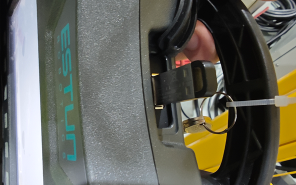
Insert the USB drive into the USB port on the teach pendant.
-
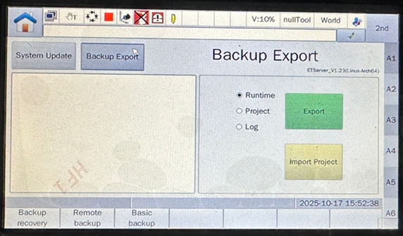
In teach mode, switch to administrator mode, then return to the main screen and navigate to . The Backup Export interface will appear.
-
Choose the desired export type (including Runtime, Project, and Log) as needed, and then tap Export. You will be prompted to enter the administrator password (default: 000000) to confirm the operation. After confirmation, it will request the export from the controller.
If the USB drive is not inserted, a prompt will appear asking to insert a USB drive. 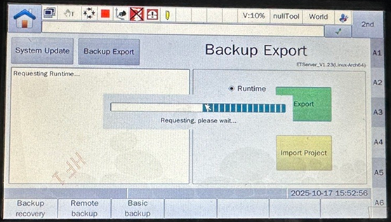
-
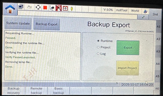
After the export request is approved, a dialog box for renaming the export file will appear. Enter the desired export name and confirm to start exporting the selected files. After the export is completed, it will display the completion status as shown in the figure below. Once confirmed, safely remove the USB drive.
-
Do not remove the USB drive before the export is finished. Otherwise, files may be missing or corrupted.
-
The backup export process takes approximately 5 to 10 minutes. Please wait patiently.
-
Load the Program Files to the Robot
-
On the IPC, open the program folder (
ESTUNfolder) and navigate to theMM_Interface.erfolder.You can also find the program folder in the
Communication Component/Robot_Interface/ESTUNpath in the installation directory of Mech-Vision and Mech-Viz. -
Use a text editor to open the
MM_AUTO_CALIBRATION.erpandMM_INIT_SKT.erpfiles. Modify the values of t_p.IP.value[1]~t_p.IP.value[4] and t_p.PORT.value based on the actual situation. t_p.IP.value[1]~t_p.IP.value[4] correspond to the four segments of the IPC’s IP address. t_p.PORT.value corresponds to the host port number set in Mech-Vision. -
Insert a USB drive into the IPC and copy the entire
MM_Interface.erfolder to the root directory of the USB drive. After the copy is complete, safely remove the USB drive. -
On the teach pendant, enter teach mode, then tap User Login on the main screen. In the Current User dropdown list, select Administrator and enter the password (default: 000000) to switch to administrator mode.
-
Insert the USB drive into the USB port on the teach pendant.
-
Press the folder button on the teach pendant.
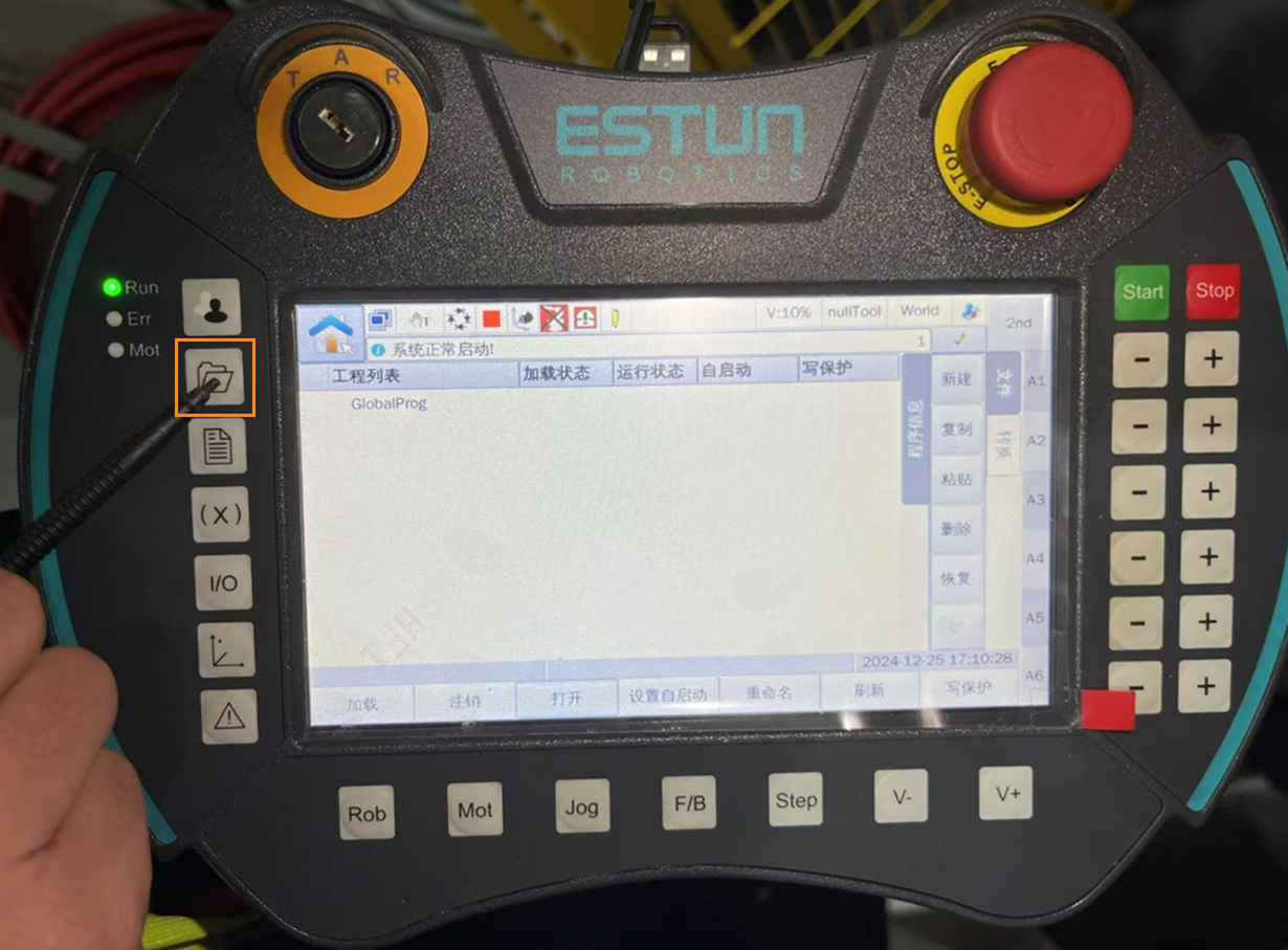
-
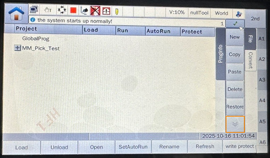
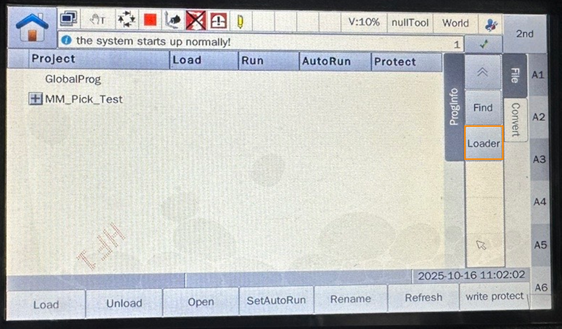
Tap the Down Arrow icon to expand, then go to .
-
Select
MM_Interface.erand tap OK.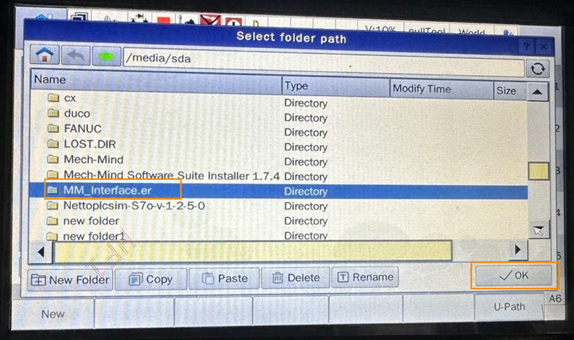
-
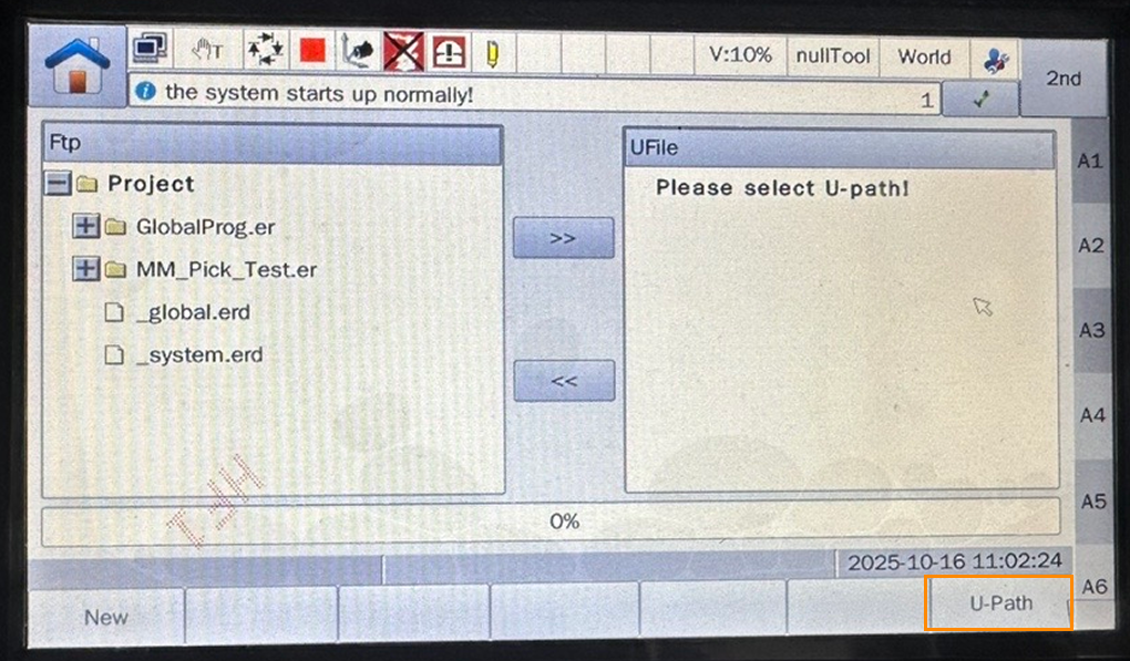
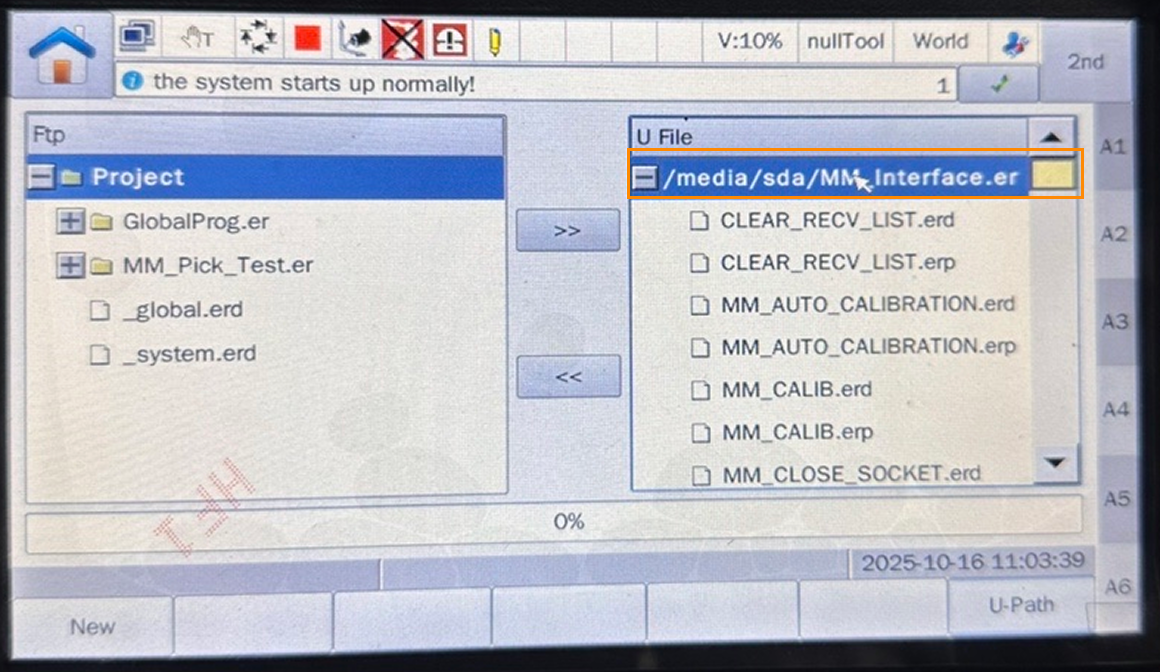
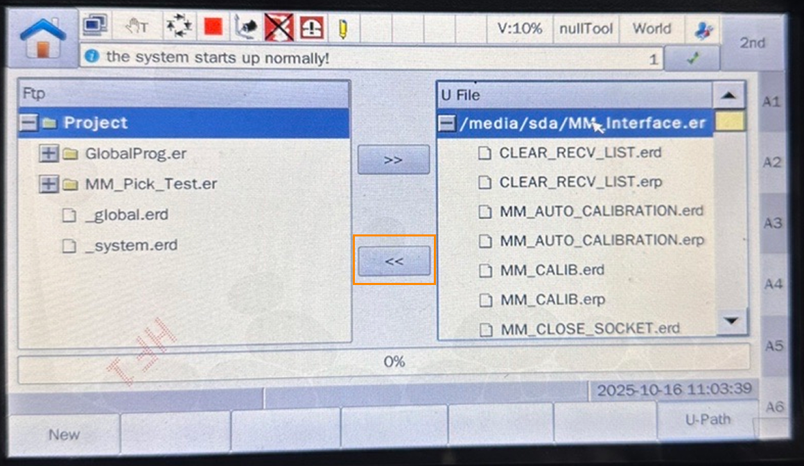
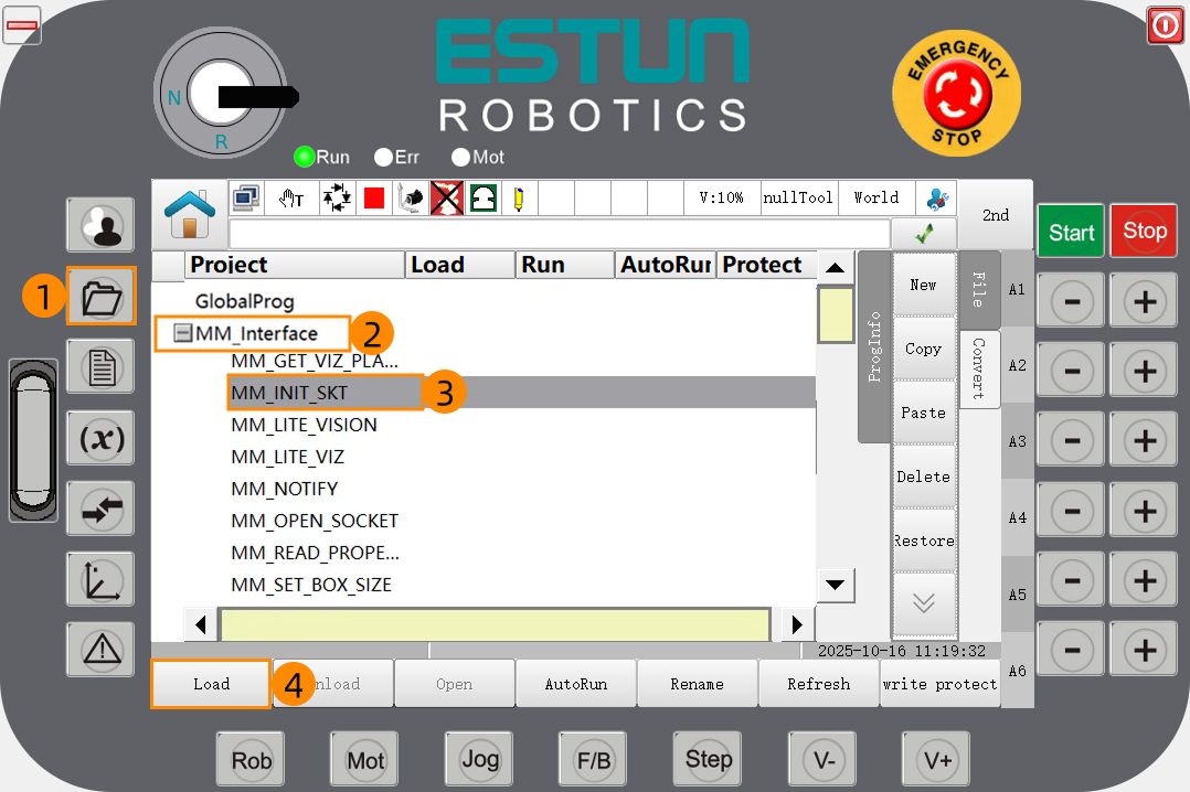
First, in the left Ftp pane, select the Project; then, in the right U File pane, select
MM_Interface.er; finally, tap the left arrow button and wait for the copy progress bar to complete.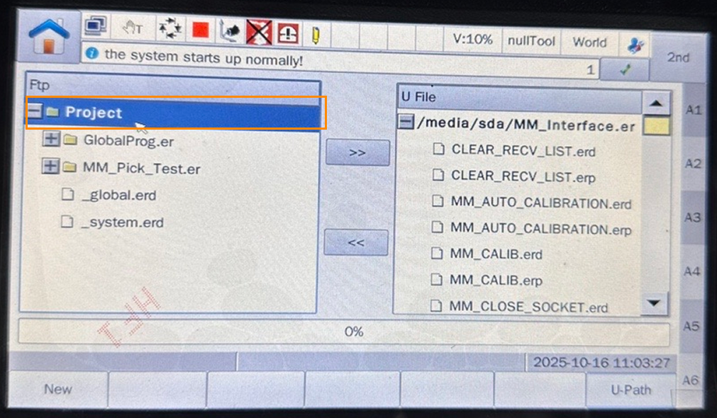
-
When
MM_Interfaceappears in the Project panel, the program has been successfully loaded.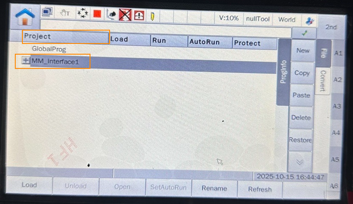
Test Standard Interface Communication
-
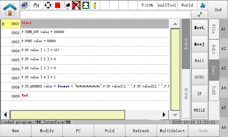
In teach mode, press the folder button on the teach pendant, expand MM_Interface, select MM_INIT_SKT, and tap Load to open the program file.
-
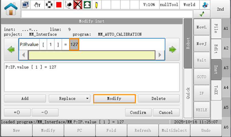
In the opened program file, check the value of P:PORT.value on line 3 (this value must match the host port number set in Mech-Vision). Then, check the values of P:IP.value[1]~P:IP.value[4] on lines 4 to 7 (these four values must correspond to the four segments of the IPC’s IP address).
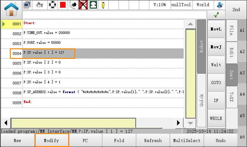
If you need to modify these values, refer to the following example. The example below demonstrates how to change 127 to 192 in line 4.
-
Select line 4 and tap Modify.
-
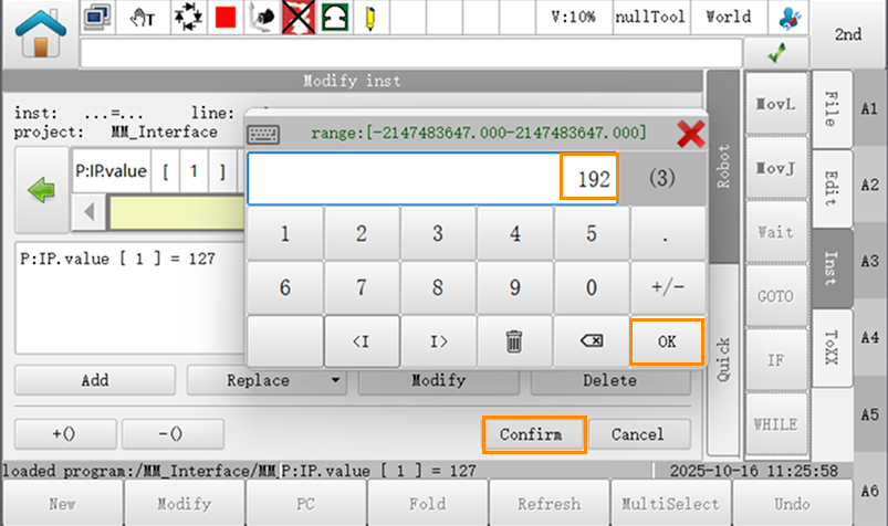
Place the cursor on 127 and tap Modify.
-
Enter 192, then tap in sequence.
-
-
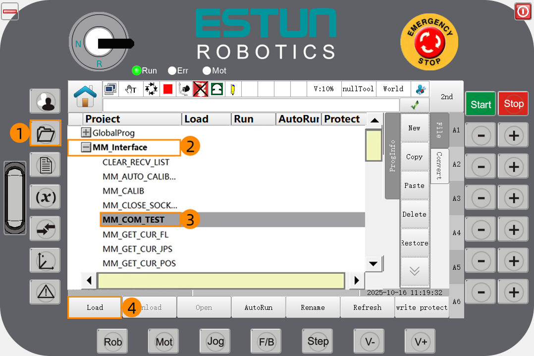
Press the folder button on the teach pendant and enter the Project view. Expand MM_Interface, select MM_COM_TEST, and tap Load to open the program file.
-
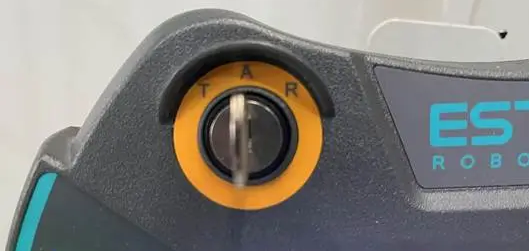
Turn the key switch on the teach pendant to position A to switch to Auto mode.
-
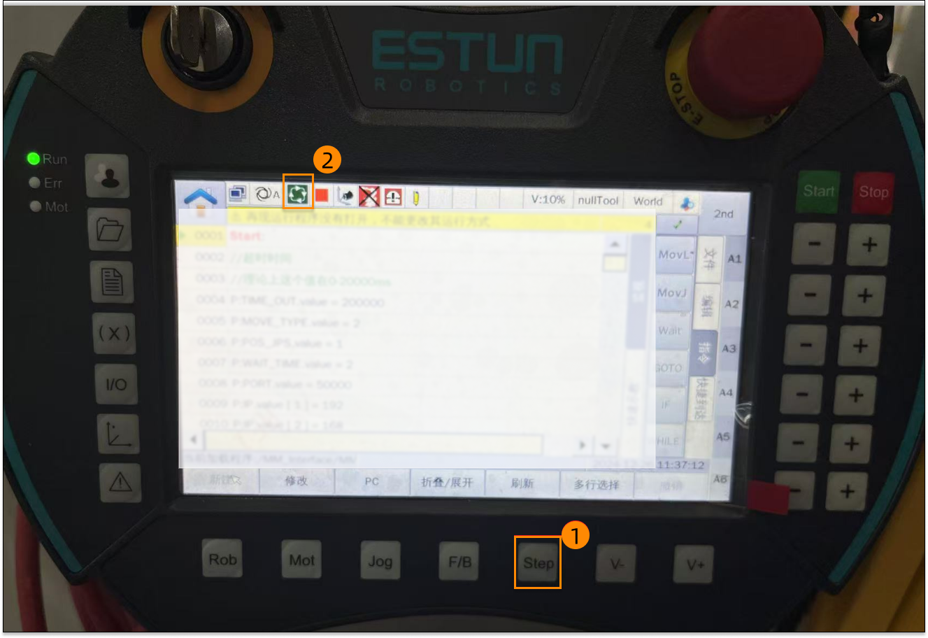
Press the Step button (position 1 in the figure) and confirm that the program is in continuous running mode (position 2 in the figure).
-
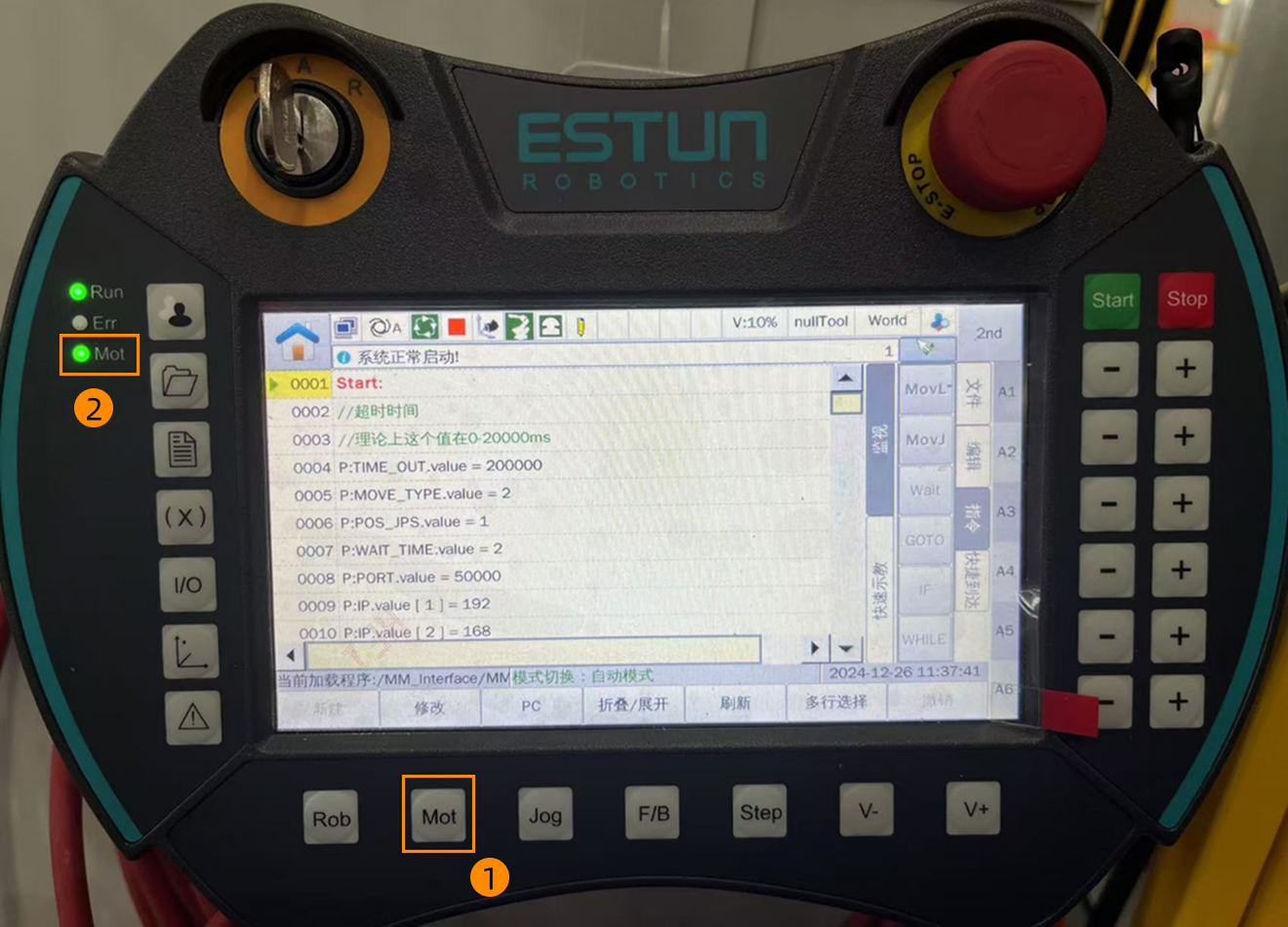
Press the Mot button (position 1 in the figure) and confirm that the enable indicator light (position 2 in the figure) is lit.
-
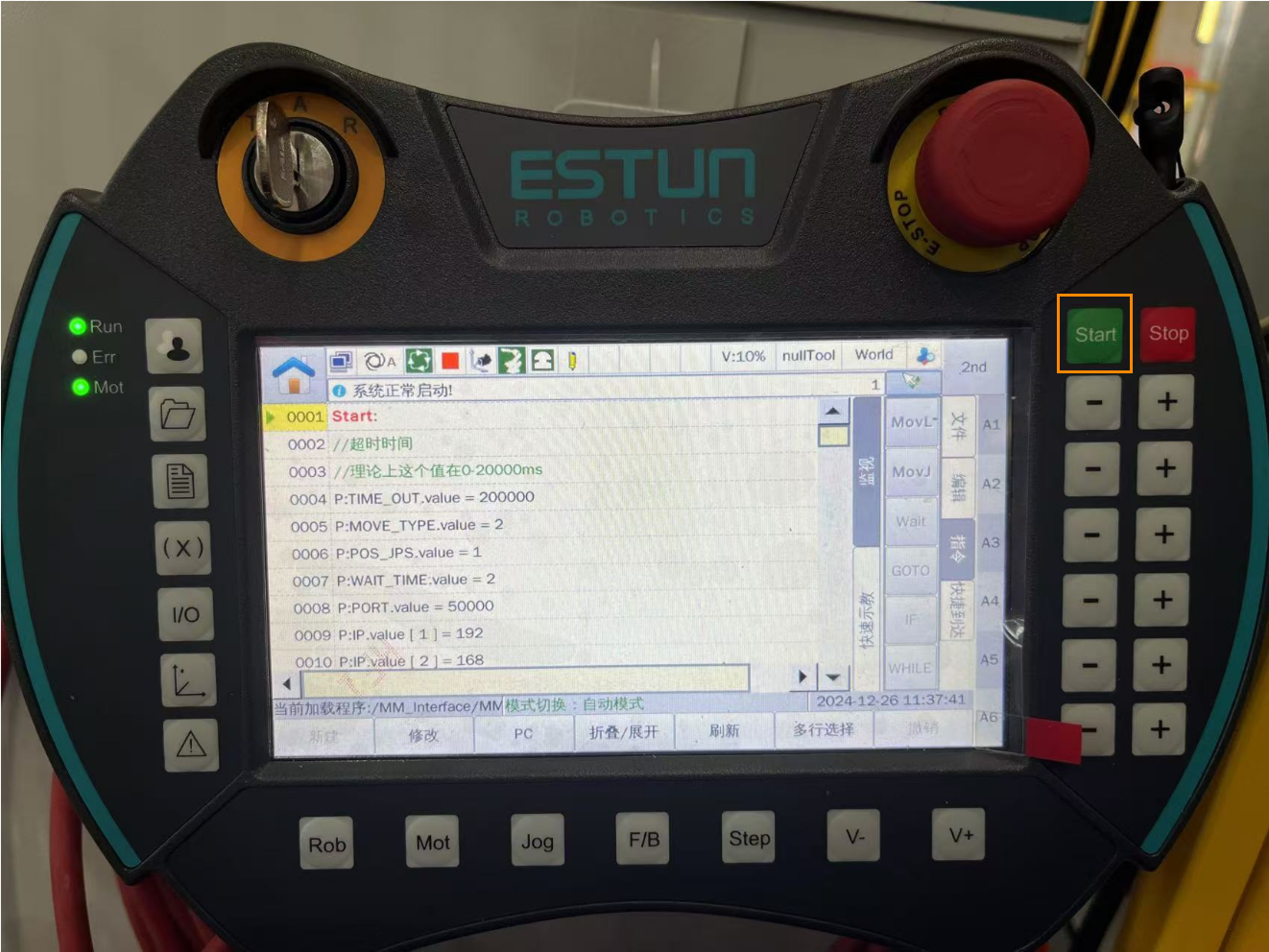
Press the Start button to run the program. Press the Stop button to stop the program.
-
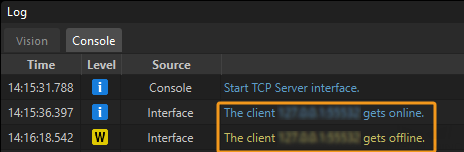
If the communication between the robot and the vision system is set up, a log will be recorded on the Console tab of the Log panel of Mech-Vision.