Example Program 7: MM_S7_Viz_SwitchTCP
Program Introduction
Description |
The robot starts the Mech-Viz project, obtains the path planning result, and then changes the tool according to the tool ID of the picking waypoint to perform picking and placing. |
File path |
You can navigate to the installation directory of Mech-Vision and Mech-Viz and find the file by using the |
Project |
Mech-Vision and Mech-Viz projects |
Prerequisites |
|
| This example program is provided for reference only. Before using the program, please modify the program according to the actual scenario. |
Program Description
This part describes the MM_S7_Viz_SwitchTCP example program.
| The only difference between the MM_S7_Viz_SwitchTCP example program and the MM_S2_Viz_Basic example program is that MM_S7_Viz_SwitchTCP can change the tool according to the tool ID(this code of this feature is bolded). As such, only the feature of handling errors based on the different error codes is described in the following part. For information about the parts of MM_S6_Viz_ErrorHandle that are consistent with those of MM_S2_Viz_Basic, see Example Program 2: MM_S2_Viz_Basic. |
   1:  !-------------------------------- ;
   2:  !FUNCTION: trigger Mech-Viz ;
   3:  !project and get planned path, ;
   4:  !switch TCP according to ;
   5:  !the tool NO.;
   6:  !Mech-Mind, 2023-12-25 ;
   7:  !-------------------------------- ;
   8:   ;
   9:  !set current uframe NO. to 0 ;
  10:  UFRAME_NUM=0 ;
  11:  !set current tool NO. to 1 ;
  12:  UTOOL_NUM=1 ;
  13:  !move to robot home position ;
  14:J P[1] 100% FINE    ;
  15:  !initialize communication ;
  16:  !parameters(initialization is ;
  17:  !required only once) ;
  18:  CALL MM_INIT_SKT('8','127.0.0.1',30000,5) ;
  19:  !move to image-capturing position ;
  20:L P[2] 1000mm/sec FINE    ;
  21:  !trigger Mech-Viz project ;
  22:  CALL MM_START_VIZ(2,10,53) ;
  23:  !check whether viz project has ;
  24:  !been triggered successfully ;
  25:  IF (R[53]<>2103),JMP LBL[99] ;
  26:  !get planned path, 1st argument ;
  27:  !(2) means getting pose in TCP ;
  28:  CALL MM_GET_VIZ(2,51,52,53) ;
  29:  !check whether planned path has ;
  30:  !been got from Mech-Viz ;
  31:  !successfully ;
  32:  IF R[53]<>2100,JMP LBL[99] ;
  33:  !save waypoints of the planned ;
  34:  !path to local variables one ;
  35:  !by one ;
  36:  CALL MM_GET_POS(1,60,70,80) ;
  37:  CALL MM_GET_POS(2,61,71,81) ;
  38:  CALL MM_GET_POS(3,62,72,82) ;
  39:  !switch TCP according to the ;
  40:  !received tool NO. ;
  41:  IF R[81]=1,JMP LBL[1] ;
  42:  IF R[81]=2,JMP LBL[2] ;
  43:  JMP LBL[999] ;
  44:   ;
  45:  LBL[1:use tool NO.1] ;
  46:  !set current tool NO. to 1 ;
  47:  UTOOL_NUM=1 ;
  48:  !reset tool signal ;
  49:  !DO[1]=OFF ;
  50:  !set a Flag ;
  51:  F[1]=(ON) ;
  52:  JMP LBL[3] ;
  53:   ;
  54:  LBL[2:use tool NO.2] ;
  55:  !set current tool NO. to 2 ;
  56:  UTOOL_NUM=2 ;
  57:  !reset tool signal ;
  58:  !DO[2]=OFF ;
  59:  !set a Flag ;
  60:  F[2]=(ON) ;
  61:  JMP LBL[3] ;
  62:   ;
  63:  LBL[3:pick path] ;
  64:  !follow the planned path to pick ;
  65:  !move to approach waypoint ;
  66:  !of picking ;
  67:L PR[60] 1000mm/sec FINE    ;
  68:  !move to picking waypoint ;
  69:L PR[61] 300mm/sec FINE    ;
  70:  !add object grasping logic here, ;
  71:  !IF (F[1]),DO[1]=(ON) ;
  72:  !IF (F[2]),DO[2]=(ON) ;
  73:  PAUSE ;
  74:  !move to departure waypoint ;
  75:  !of picking ;
  76:L PR[62] 1000mm/sec FINE    ;
  77:  !move to intermediate waypoint ;
  78:  !of placing ;
  79:J P[3] 50% CNT100    ;
  80:  !move to approach waypoint ;
  81:  !of placing ;
  82:L P[4] 1000mm/sec FINE Tool_Offset,PR[2]    ;
  83:  !move to placing waypoint ;
  84:L P[4] 300mm/sec FINE    ;
  85:  !add object releasing logic here, ;
  86:  !IF (F[1]),DO[1]=(OFF) ;
  87:  !IF (F[2]),DO[2]=(OFF) ;
  88:  PAUSE ;
  89:  !move to departure waypoint ;
  90:  !of placing ;
  91:L P[4] 1000mm/sec FINE Tool_Offset,PR[2]    ;
  92:  !move back to robot home position ;
  93:J P[1] 100% FINE    ;
  94:  !reset the Flags ;
  95:  F[1]=(OFF) ;
  96:  F[2]=(OFF) ;
  97:  END ;
  98:   ;
  99:  LBL[99:vision error] ;
 100:  !add error handling logic here ;
 101:  !according to different ;
 102:  !error codes ;
 103:  !e.g.: status=2038 means no ;
 104:  !point cloud in ROI ;
 105:  !e.g.: mm_status=3099 means ;
 106:  !failed to open socket ;
 107:  PAUSE ;
 108:   ;
 109:  LBL[999:label error] ;
 110:  !add handling logic here if the ;
 111:  !label is invalid ;
 112:  PAUSE ;
The workflow corresponding to the above example program code is shown in the figure below.
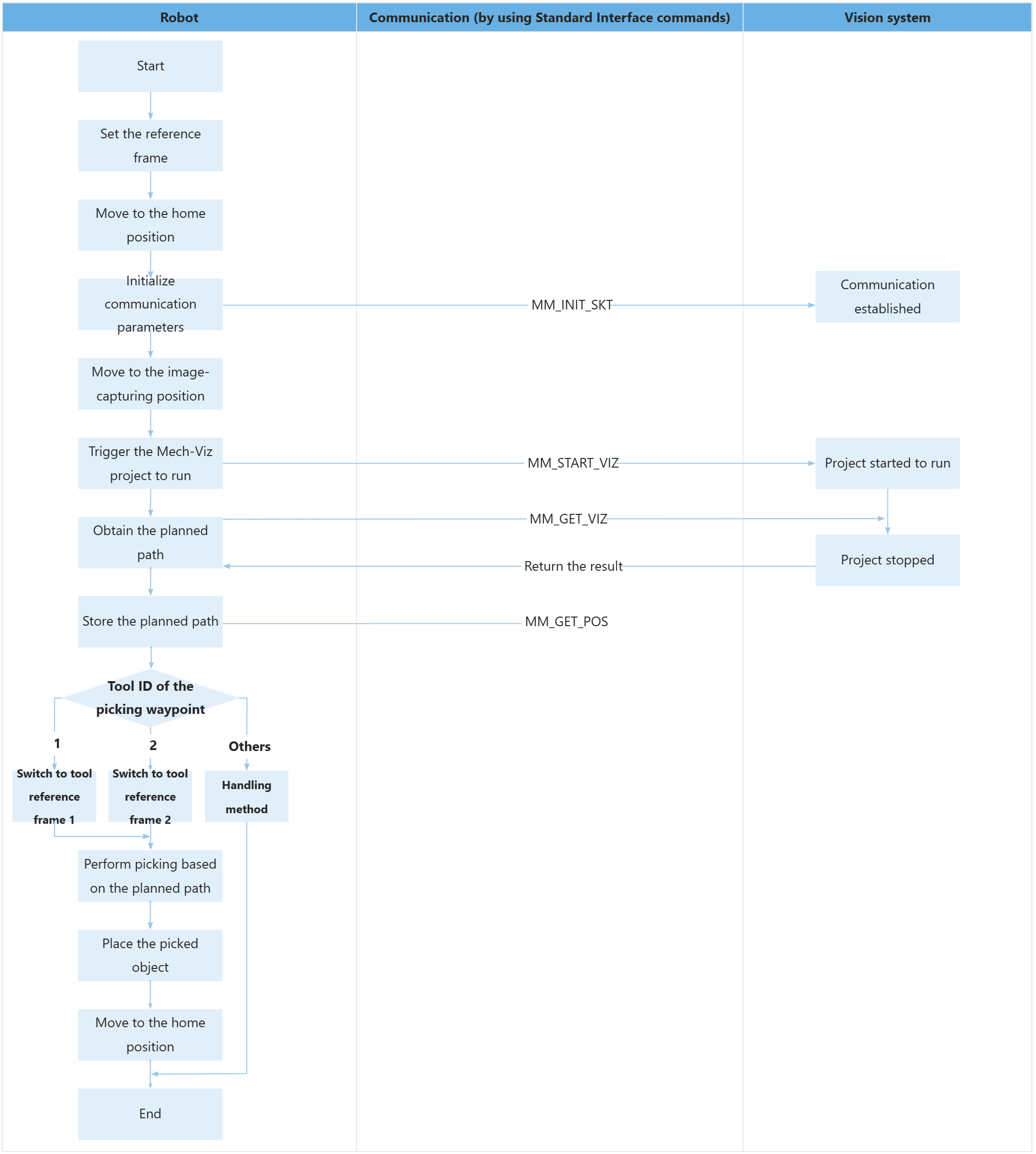
The table below describes the bolded code.
| Feature | Code and description | ||
|---|---|---|---|
Obtain the planned path |
The entire statement indicates that the robot obtains the planned path from the Mech-Viz project.
|
||
Store the planned path |
The entire command “CALL MM_GET_JPS(1,60,70,80)” stores the TCP, label, and tool ID of the first waypoint in the specified registers.
|
||
Change the tool based on the tool ID |
You can determine the tool to be used when the robot moves to the picking waypoint based on the value set in the R[81] register. The description of the above code is shown below.
If the robot controls tool 1 with the DO[1] signal and tool 2 with the DO[2] signal, the program must also establish their relationships using flags F[1] and F[2] respectively.
In the following example, No.1 tool ID is used to describe the pick-and-place operation.
The process for using No.2 tool ID is similar to the above, and will not be repeated here. |