Common Commands
This guide describes the commands commonly used in AB PLC ladder diagrams, as shown in the following table.
| Ladder diagram | Command | Description |
|---|---|---|

|
Latch (OTL) |
When the rung condition is True, the OTL command sets data_bit to True. data_bit remains true until it is cleared, typically by an Output Unlatch (OTU) command. When the rung condition is changed to False, the OTL command does not change the status of data_bit. |

|
Unlatch (OTU) |
When the rung condition is True, the OTU command sets data_bit to False. When the rung condition is changed to False, the OTU command does not change the status of data_bit. |

|
Examine On (XIC) |
If data_bit is set to True, the rung output condition is set to True. If data_bit is set to False, the rung output condition is set to False. |

|
Examine Off (XIO) |
If data_bit is set to True, the rung output condition is set to False. If data_bit is set to False, the rung output condition is set to True. |

|
One Shot (ONS) |
Make the remainder of the rung True each time the rung input condition transitions from False to True. |
|
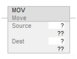
Move (MOV) |
Move the copy of the source to the destination. The source remains unchanged. |
|
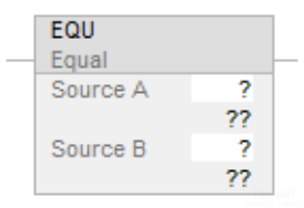
Equal to (EQU) |
If Source A and Source B are numbers, and Source A equals Source B, set the rung output condition to True; otherwise, set the rung output condition to False. |
|
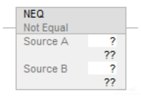
Not Equal to (NEQ) |
If Source A or Source B is not a number (NAN), or Source A does not equal Source B, set the rung output condition to True; otherwise, set the rung output condition to False. |
|
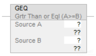
Greater than or Equal to (GEQ) |
If Source A and Source B are numbers, and Source A is greater than or equal to Source B, set the rung output condition to True; otherwise, set the rung output condition to False. |
|
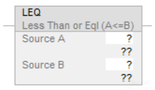
Less than or Equal to (LEQ) |
If Source A and Source B are numbers, and Source A is less than or equal to Source B, set the rung output condition to True; otherwise, set the rung output condition to False. |
|
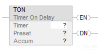
Timer On Delay (TON) |
Start accumulating time when it is enabled, until the timer is disabled or the timer completes.
|
|
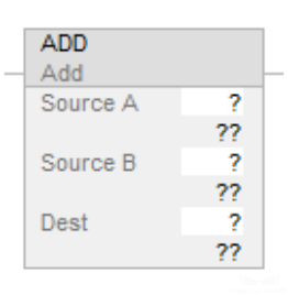
Addition (ADD) |
If the rung input condition is True, the destination equals Source A plus Source B. |