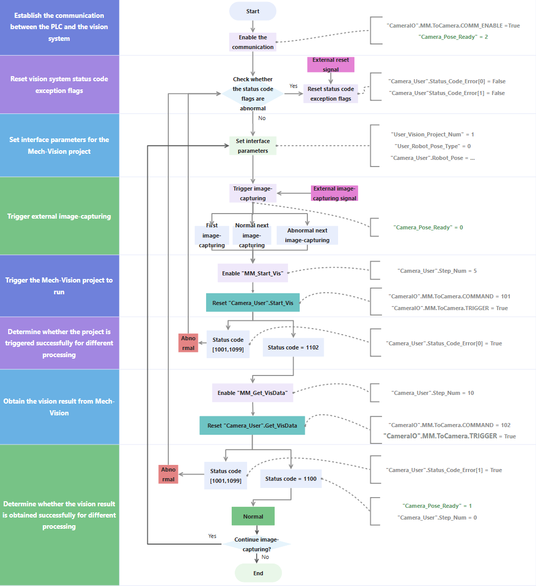
Establish the communication between PLC and the vision system |
-
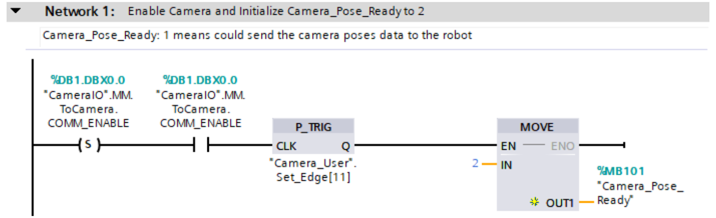
"CameraIO".MM.ToCamera.COMM_ENABLE: Determine whether communication is enabled. Valid values:
-
P_TRIG: Detect the rising edge of the logical operation result when "CameraIO".MM.ToCamera.COMM_ENABLE is True.
-
MOVE: Set "Camera_Pose_Ready" to 2.
-
"Camera_Pose_Ready": Indicate whether the PLC obtained the vision result. Valid values:
-
0: The PLC did not obtain the vision result when the camera was about to capture images or had already captured images, or when Mech-Vision was calculating the vision result.
-
1: The camera captured images, and the PLC obtained the vision result.
-
2: The camera was ready to start capturing images for the first time, and the PLC did not obtain the vision result.
As such, Network 1 indicates that only when "CameraIO".MM.ToCamera.COMM_ENABLE is set to True and P_TRIG detects a rising edge, "Camera_Pose_Ready" is initialized to 2.
|
Reset vision system status code exception flags |
-
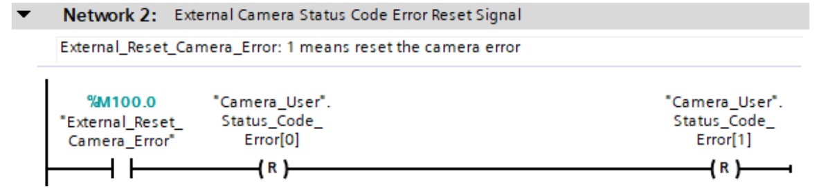
"Camera_User".Status_Code_Error[0]: A vision system status code exception flag. True indicates that the Mech-Vision project was not successfully run, i.e., an exception occurred in the vision system.
-
"Camera_User".Status_Code_Error[1]: A vision system status code exception flag. True indicates that the Mech-Vision project failed to output the vision result, i.e., an exception occurred in the vision system.
-
"External_Reset_Camera_Error": An external reset signal. When an exception occurs in the vision system and the signal changes from False to True, the succeeding "Camera_User".Status_Code_Error[0] and "Camera_User".Status_Code_Error[1] are reset.
As such, Network 2 indicates that when "External_Reset_Camera_Error" is conducting, "Camera_User".Status_Code_Error[0] and "Camera_User".Status_Code_Error[1] are reset.
|
Set interface parameters for the Mech-Vision project |
-
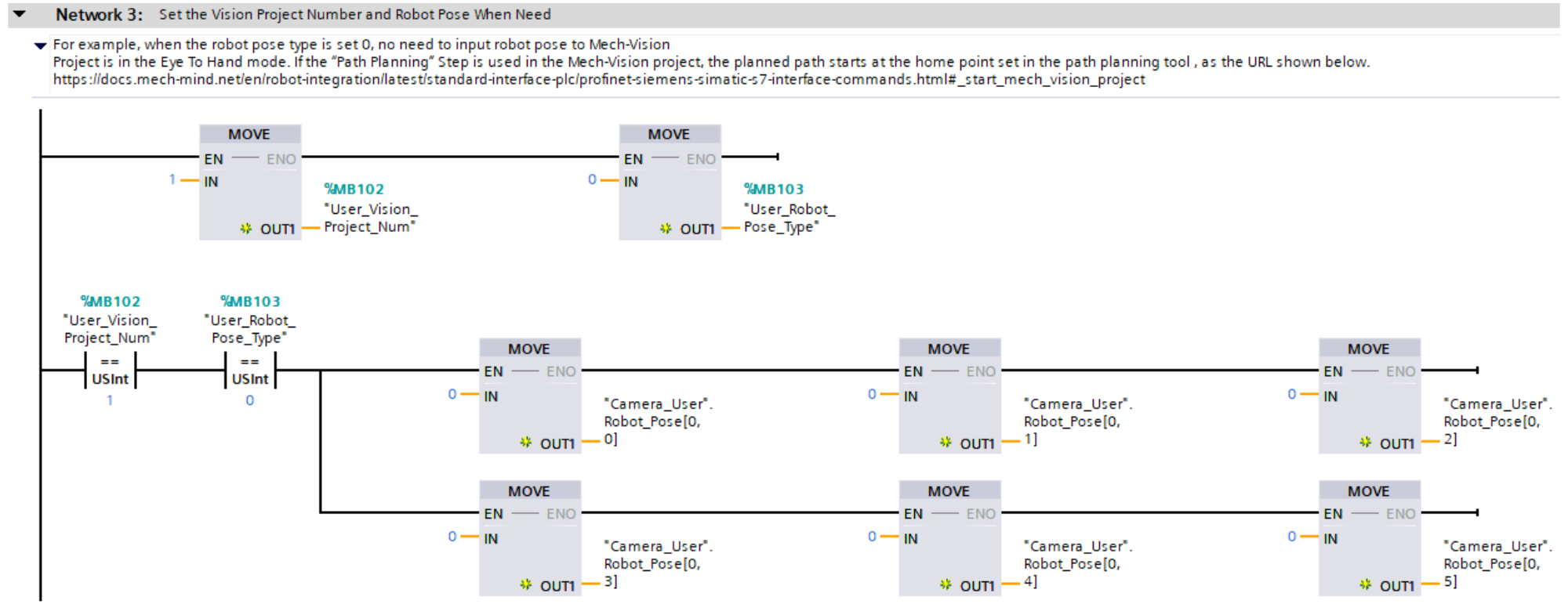
"User_Vision_Project_Num": The Mech-Vision project ID.
-
"User_Robot_Pose_Type": Specify the pose type of the real robot to input to the Mech-Vision project. This value of this parameter should be set as the value of Robot_Pose_Type of the MM_Start_Vis command. In this example, the parameter value is 0. You can modify the value as needed.
-
"Camera_User".Robot_Pose[0,0] ~ [0,5]: Six pieces of joint position data of the robot. This value of this parameter should be set as the value of Robot_Pose[0,0]~[0,5] of the MM_Start_Vis command. In this example, the parameter value is 0. You can modify the value as needed and add the robot flange pose data, i.e., the value of the Robot_Pose[1,0]~[1,5] parameter in the MM_Start_Vis command.
As such, in Network 3, Mech-Vision project ID is set to 1 and "User_Robot_Pose_Type" is set to 0. If the Mech-Vision project ID is set to 1 and "User_Robot_Pose_Type" is set to 0, "Camera_User".Robot_Pose[0,0]~[0,5] are set to 0 sequentially.
|
Trigger external image capturing |
-
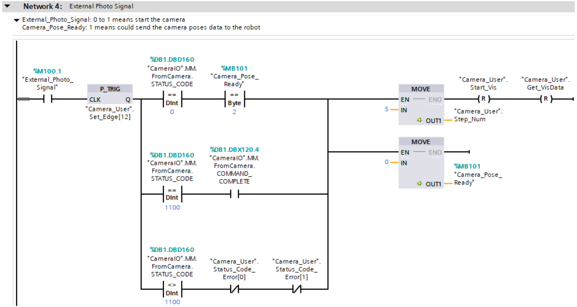
"External_Photo_Signal": The external signal to trigger image capturing when a rising edge occurs.
-
"CameraIO".MM.FromCamera.STATUS_CODE: A vision system status code. 1102 indicates that the PLC successfully triggered the Mech-Vision project to run. 1100 indicates that the PLC successfully obtained the vision result.
-
"Camera_User".Start_Vis: The flag that triggers the Mech-Vision project to run when the rising edge occurs.
-
"Camera_User".Get_VisData: The flag that triggers the retrieval of Mech-Vision vision result when the rising edge occurs.
As such, Network 4 indicates that the external signal to trigger image capturing when a rising edge occurs is retrieved, and then the following three image capturing operations are performed.
-
An image is captured for the first time. "CameraIO".MM.FromCamera.STATUS_CODE is set to 0, and "Camera_Pose_Ready" is set to 2.
-
An image is captured normally at the next time. "CameraIO".MM.FromCamera.STATUS_CODE is set to 1100.
-
An error is reported when an image is captured at the next time. "CameraIO".MM.FromCamera.STATUS_CODE does not equal 1100, and both "Camera_User".Status_Code_Error[0] and "Camera_User".Status_Code_Error[1] are set to False.
Finally, "Camera_User".Step_Num is set to 5, "Camera_User".Start_Vis and "Camera_User".Get_VisData are reset, and "Camera_Pose_Ready" is set to 0.
|
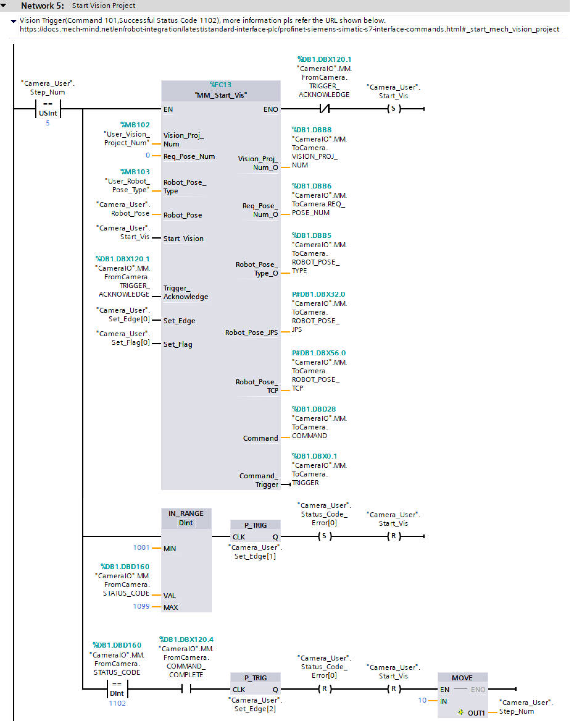
Trigger the Mech-Vision project to run and determine whether the project is triggered successfully for different processing |
|
|
For more information about input and output parameters in MM_Start_Vis, see MM_Start_Vis.
|
Network 5 indicates that if "Camera_User".Step_Num is set to 5, the following operations are performed.
-
MM_Start_Vis is enabled. In this case, Req_Pose_Num is set to 0 by default, which means all vision points are obtained. The maximum number of vision points is 20.
-
When "MM_Start_Vis".ENO is True and "CameraIO".MM.FromCamera.TRIGGER_ACKNOWLEDGE is False, "Camera_User".Start_Vis is set and the PLC will trigger the Mech-Vision project to run.
-
If the value of "CameraIO".MM.FromCamera.STATUS_CODE is greater than or equal to 1001 and less than or equal to 1099, an exception occurred in the vision system. In this case, after the rising edge for the logic output is obtained by using the P_TRIG command, "Camera_User".Status_Code_Error[0] is set and "Camera_User".Start_Vis is reset. For information about the cause of a specific status code, see Standard Interface status codes and error codes.
-
If "CameraIO".MM.FromCamera.STATUS_CODE equals 1102 and "CameraIO".MM.FromCamera.COMMAND_COMPLETE is True, it means the vision system has successfully executed the command sent by the PLC. At this point, the rising edge of this logical output is captured using the P_TRIG command, "Camera_User".Status_Code_Error[0] and "Camera_User".Start_Vis are reset, and "Camera_User".Step_Num is set to 10.
|
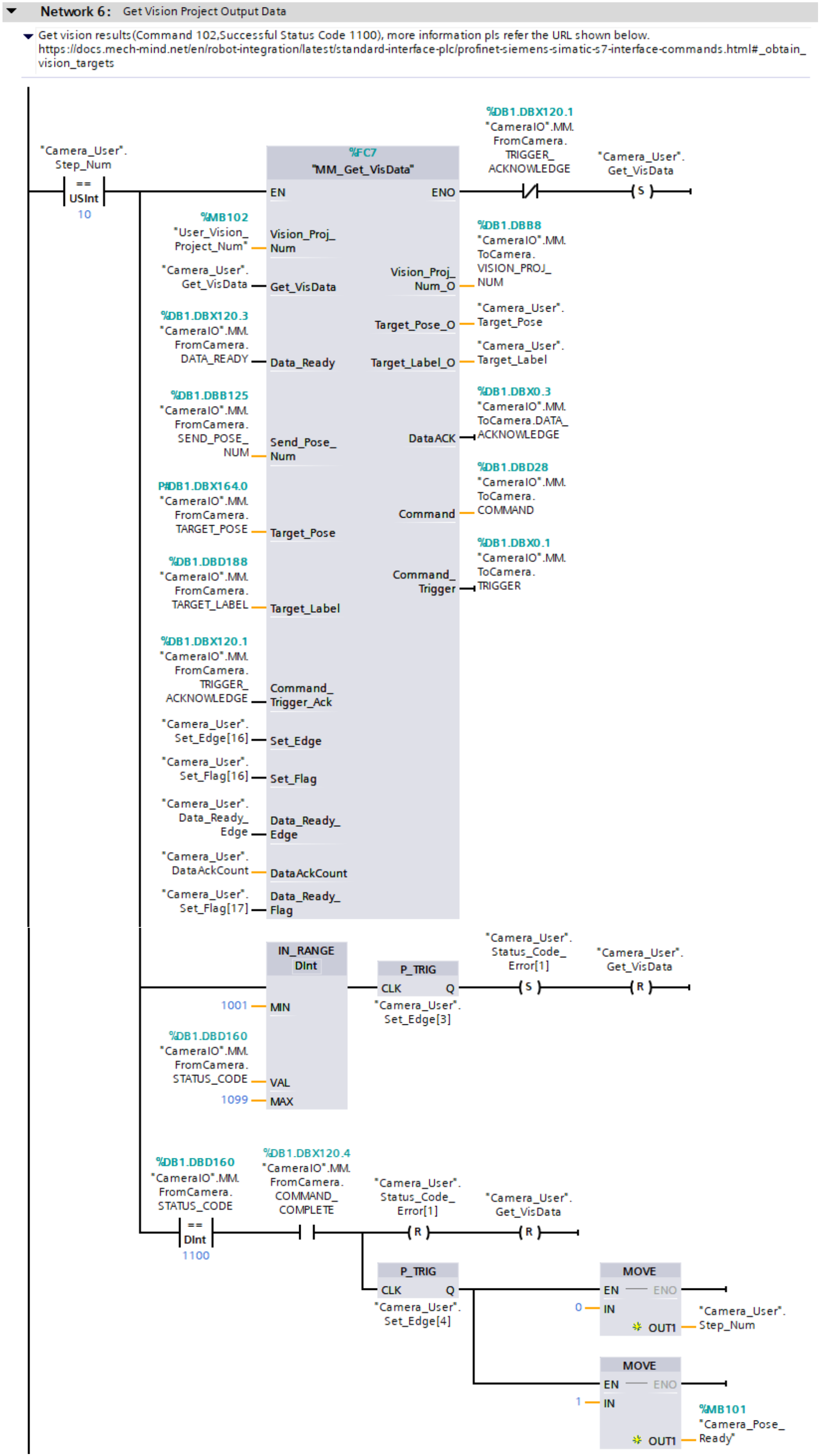
Obtain the vision result of the Mech-Vision project and determine whether the vision result is obtained successfully for different processing |
|
|
For more information about input and output parameters in MM_Get_VisData, see MM_Get_VisData.
|
Network 6 indicates that if "Camera_User".Step_Num is set to 10, the following operations are performed.
-
MM_Get_VisData is enabled.
-
When "MM_Get_VisData".ENO is True and "CameraIO".MM.FromCamera.TRIGGER_ACKNOWLEDGE is False, "Camera_User".Get_VisData is set and the PLC starts retrieving the vision result exported by the Mech-Vision project.
-
If "CameraIO".MM.FromCamera.STATUS_CODE is between 1001 and 1099 (inclusive), it indicates a vision system error. At this point, the rising edge of this logical output is captured using the P_TRIG command, "Camera_User".Status_Code_Error[1] is set, and "Camera_User".Get_VisData is reset. For information about the cause of a specific status code, see Standard Interface status codes and error codes.
-
If "CameraIO".MM.FromCamera.STATUS_CODE equals 1100 and "CameraIO".MM.FromCamera.COMMAND_COMPLETE is True, it means the vision system has successfully executed the command sent by the PLC. At this point, "Camera_User".Status_Code_Error[1] and "Camera_User".Get_VisData are reset. The P_TRIG command is used to capture the rising edge of the logical output when "CameraIO".MM.FromCamera.STATUS_CODE equals 1100 and "CameraIO".MM.FromCamera.COMMAND_COMPLETE is True, "Camera_User".Step_Num is set to 0, and "Camera_Pose_Ready" is set to 1. This indicates that the PLC has received the vision result and can now forward the result to the robot.
|