サンプルプログラム16:MM_S16_Viz_GetDirection
プログラム概要
機能 |
ロボットが計画された経路を取得し、把持を実行した後、ワーク群の向きに基づいて異なる配置方法を使用します。 |
ファイル場所 |
Mech-VisionとMech-Vizソフトウェアのインストールディレクトリにある |
必要なプロジェクト |
Mech-Visionプロジェクト、Mech-Vizプロジェクト(ロボットハンド種類がデパレタイズ用吸盤である必要があります) |
使用前提 |
|
| このサンプルプログラムは参考用です。ユーザーは実際の状況に応じて、このプログラムを基に変更を加える必要があります。このプログラムをそのまま使用しないでください。 |
プログラム説明
以下はMM_S16_Viz_GetDirectionサンプルプログラムのコードと関連する説明です。
| このサンプルは、MM_S15_Viz_GetDoListサンプルに比べて、太字部分のコードのみが追加されています。そのため、MM_S15_Viz_GetDoListサンプルと同じ部分のコードについては、以下で再度説明することはありません(詳細は MM_S15_Viz_GetDoListサンプルの説明 をご参照ください)。 |
1: !-------------------------------- ;
2: !FUNCTION: trigger Mech-Viz ;
3: !project, then get planned path ;
4: !and get box direction using ;
5: !command 210 ;
6: !Mech-Mind, 2023-12-25 ;
7: !-------------------------------- ;
8: ;
9: !set current uframe NO. to 0 ;
10: UFRAME_NUM=0 ;
11: !set current tool NO. to 1 ;
12: UTOOL_NUM=1 ;
13: !move to robot home position ;
14:J P[1] 100% FINE ;
15: !initialize communication ;
16: !parameters(initialization is ;
17: !required only once) ;
18: CALL MM_INIT_SKT('8','127.0.0.1',30000,5) ;
19: !move to image-capturing position ;
20:L P[2] 1000mm/sec FINE ;
21: !trigger Mech-Viz project ;
22: CALL MM_START_VIZ(2,10,53) ;
23: !check whether viz project has ;
24: !been triggered successfully ;
25: IF (R[53]<>2103),JMP LBL[99] ;
26: !get planned path ;
27: CALL MM_GET_PLNDT(0,3,51,52,53) ;
28: !check whether planned path has ;
29: !been got from Mech-Viz ;
30: !successfully ;
31: IF R[53]<>2100,JMP LBL[99] ;
32: !get gripper control signal list ;
33: CALL MM_GET_DL(0,0,53) ;
34: !check whether viz DoList has ;
35: !been gotten successfully ;
36: IF (R[53]<>2102),JMP LBL[99] ;
37: !save waypoints of the planned ;
38: !path to local variables one ;
39: !by one ;
40: CALL MM_GET_PLJOP(1,3,60,61,62,63,64,70) ;
41: CALL MM_GET_PLJOP(2,3,61,91,92,93,94,100) ;
42: CALL MM_GET_PLJOP(3,3,62,121,122,123,124,130) ;
43: !get box direction status from ;
44: !planned results of 2nd point ;
45: レジ[10]=レジ[116] ;
46: !follow the planned path to pick ;
47: !move to approach waypoint ;
48: !of picking ;
49:J PR[60] 50% FINE ;
50: !move to picking waypoint ;
51:J PR[61] 10% FINE ;
52: !add object grasping logic here ;
53: PAUSE ;
54: !set gripper control signal ;
55: CALL MM_SET_DL(0) ;
56: !move to departure waypoint ;
57: !of picking ;
58:J PR[62] 50% FINE ;
59: !place the box according to its ;
60: !direction ;
61: IF R[10]=0,JMP LBL[1] ;
62: IF R[10]<>0,JMP LBL[2] ;
63: ;
64: LBL[1:place position 1] ;
65: !move to intermediate waypoint ;
66: !of placing ;
67:J P[3] 50% CNT100 ;
68: !move to approach waypoint ;
69: !of placing ;
70:L P[4] 1000mm/sec FINE Tool_Offset,PR[2] ;
71: !move to placing waypoint ;
72:L P[4] 300mm/sec FINE ;
73: !add object releasing logic here, ;
74: !such as "DO[1]=OFF" ;
75: PAUSE ;
76: !move to departure waypoint ;
77: !of placing ;
78:L P[4] 1000mm/sec FINE Tool_Offset,PR[2] ;
79: JMP LBL[3] ;
80: ;
81: LBL[2:place position 2] ;
82: !move to intermediate waypoint ;
83: !of placing ;
84:J P[5] 50% CNT100 ;
85: !move to approach waypoint ;
86: !of placing ;
87:L P[6] 1000mm/sec FINE Tool_Offset,PR[2] ;
88: !move to placing waypoint ;
89:L P[6] 300mm/sec FINE ;
90: !add object releasing logic here, ;
91: !such as "DO[1]=OFF" ;
92: PAUSE ;
93: !move to departure waypoint ;
94: !of placing ;
95:L P[6] 1000mm/sec FINE Tool_Offset,PR[2] ;
96: JMP LBL[3] ;
97: ;
98: LBL[3] ;
99: !move back to robot home position ;
100:J P[1] 100% FINE ;
101: END ;
102: ;
103: LBL[99:vision error] ;
104: !add error handling logic here ;
105: !according to different ;
106: !error codes ;
107: !e.g.: status=2038 means no ;
108: !point cloud in ROI ;
109: !e.g.: mm_status=3099 means ;
110: !failed to open socket ;
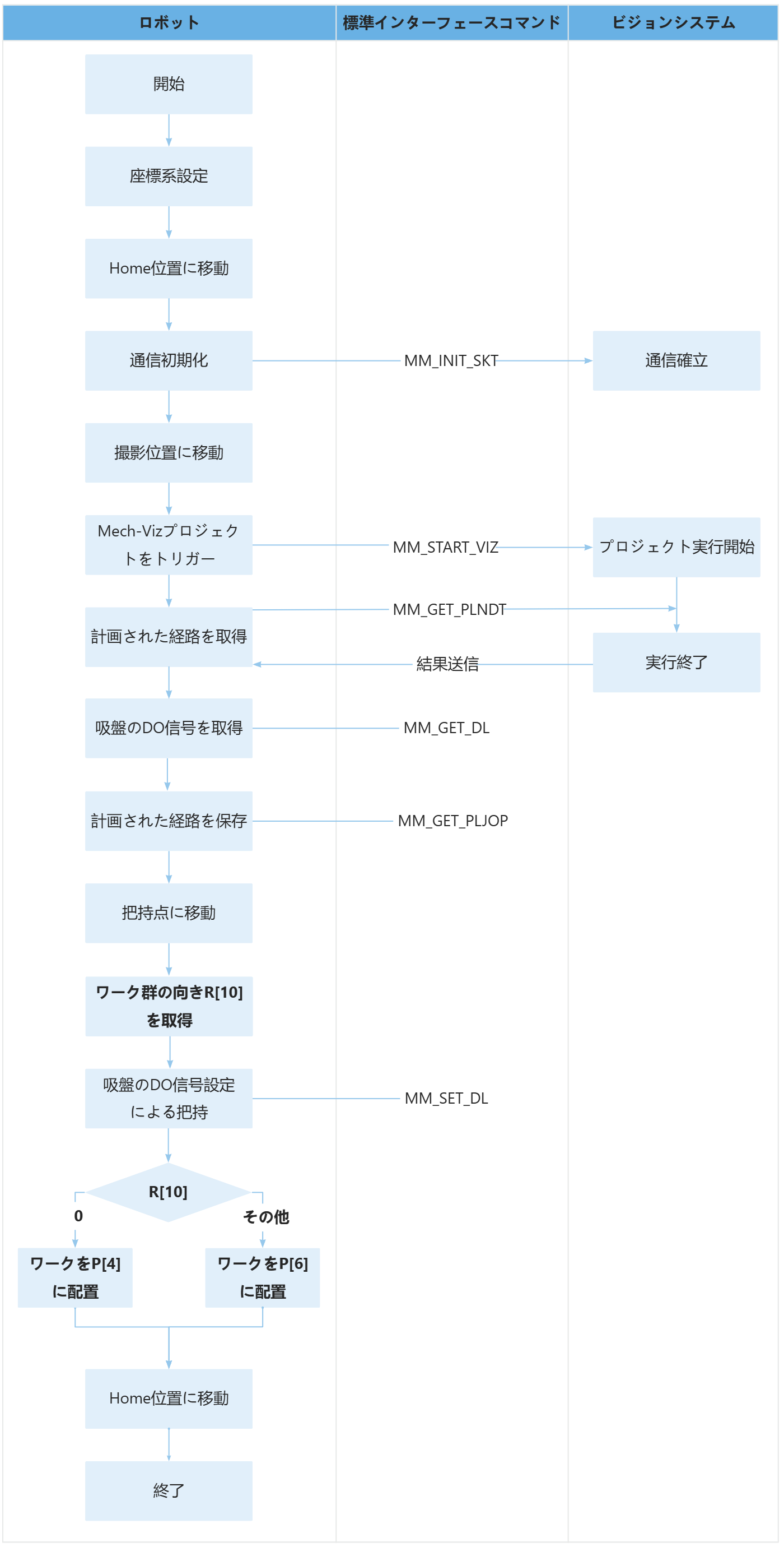
111: PAUSE ;上記のサンプルプログラムの処理流れは、下図の通りです。
下表は太字部分のコードとその説明です。コマンド名のリンクをクリックすることで、その詳細な説明を確認できます。
| 処理流れ | コートと説明 | ||
|---|---|---|---|
ワーク群の向きを取得 |
ロボットは MM_GET_PLNDT コマンドを使用して経路点の「ビジョン処理による移動」の計画結果を取得し、その後、MM_GET_PLJOP コマンドを通じて経路点の「ビジョン処理による移動」の計画結果をロボットメモリから指定されたレジスタに保存します。このサンプルでは、把持点(イチレジ[61])の「ビジョン処理による移動」の計画結果がレジ[100]から格納されます。レジ[116]はワーク群と吸盤の長辺の方向関係を示し、0は平行、1は垂直を意味します。 上記のコードは、レジ[116]をレジ[10]に代入することを意味します。その結果、レジ[10]はワーク群の向きを表すことになります。 |
||
ワーク群の向きに基づいて異なる配置方法を使用 |
上記のコードは、ワーク群が吸盤の長辺と平行している場合(レジ[10]が0の場合)、そのワーク群をイチ[4]に配置し、それ以外の場合はワーク群をイチ[6]に配置することを意味します。 |