샘플 프로그램11: MM_S11_Viz_Timer
프로그램 소개
기능 설명 |
로봇은 타이머를 사용하여 통신을 구축부터 피킹 및 배치 작업을 완료될 때까지 소요된 시간을 계산합니다. |
파일 경로 |
Mech-Vision 및 Mech-Viz의 설치 디렉터리로 이동하여 |
필요한 프로젝트 |
Mech-Vision와 Mech-Viz 프로젝트 |
사용 전제 조건 |
|
| 이 샘플 프로그램은 참고용으로 제공됩니다. 사용자는 실제 상황에 맞춰 이 내용을 바탕으로 수정해야 하며, 해당 프로그램을 그대로 사용하지 않도록 하십시오. |
프로그램 설명
다음에는 MM_S11_Viz_Timer 샘플 프로그램의 코드와 관련 설명입니다.
| MM_S2_Viz_Basic 샘플과 비하면, 이 샘플은 타이머의 기능만 추가되었습니다.(이 기능의 코드가 굵게 표시됨). 따라서 MM_S2_Viz_Basic과 일치하는 부분은 다시 설명하지 않습니다. (일치하는 부분에 대한 정보는 MM_S2_Viz_Basic샘플 프로그램 설명을 참조하십시오). |
DEF  MM_S11_Viz_Timer ( )
;---------------------------------------------------
; FUNCTION: trigger Mech-Viz project and get
; planned path, add a timer to record cycle time
; Mech-Mind, 2023-12-25
;---------------------------------------------------
   ;set current tool no. to 1
   BAS(#TOOL,1)
   ;set current base no. to 0
   BAS(#BASE,0)
   ;move to robot home position
PTP HOME Vel=100 % DEFAULT
   ;initialize communication parameters (initialization is required only once)
   MM_Init_Socket("XML_Kuka_MMIND",873,871,60)
LOOP
   ;reset timer to 0
   $TIMER[1] = 0
   ;start timer
   $TIMER_STOP[1] = FALSE
   ;move to image-capturing position
LIN camera_capture Vel=1 m/s CPDAT1 Tool[1] Base[0]
   ;trigger Mech-Viz project
   MM_Start_Viz(2,init_jps,status)
   IF status <> 2103 THEN
       ;add error handling logic here according to different error codes
       MM_LOG("Status ERROR")
       HALT
   ENDIF
   ;get planned path, 1st argument (1) means getting pose in JPs
   MM_Get_VizData(1,pos_num,vis_pos_num,status)
   ;check whether planned path has been got from Mech-Viz successfully
   IF status<> 2100 THEN
      ;add error handling logic here according to different error codes
      ;e.g.: status=2038 means no point cloud in ROI
      halt
   ENDIF
   ;save waypoints of the planned path to local variables one by one
   MM_Get_Jps(1,Xpick_point1,label[1],toolid[1])
   MM_Get_Jps(2,Xpick_point2,label[2],toolid[2])
   MM_Get_Jps(3,Xpick_point3,label[3],toolid[3])
   ;follow the planned path to pick
   ;move to approach waypoint of picking
PTP pick_point1 Vel=50 % PDAT1 Tool[1] Base[0]
   ;move to picking waypoint
PTP pick_point2 Vel=10 % PDAT2 Tool[1] Base[0]
   ;add object grasping logic here, such as "$OUT[1]=TRUE"
   halt
   ;move to departure waypoint of picking
PTP pick_point3 Vel=50 % PDAT3 Tool[1] Base[0]
   ;move to intermediate waypoint of placing
PTP drop_waypoint CONT Vel=100 % PDAT2 Tool[1] Base[0]
   ;move to approach waypoint of placing
LIN drop_app Vel=1 m/s CPDAT3 Tool[1] Base[0]
   ;move to placing waypoint
LIN drop Vel=0.3 m/s CPDAT4 Tool[1] Base[0]
   ;add object releasing logic here, such as "$OUT[1]=FALSE"
   halt
   ;move to departure waypoint of placing
LIN drop_app Vel=1 m/s CPDAT3 Tool[1] Base[0]
   ;move back to robot home position
PTP HOME Vel=100 % DEFAULT
   $TIMER_STOP[1] = TRUE
   offset = 0
   SWRITE(str_tmp[], state, offset,"time: %d ms", $TIMER[1])
   MM_LOG(str_tmp[])
ENDLOOP
END
위 샘플 프로그램 코드에 해당하는 워크플로는 아래 그림에 표시되어 있습니다.
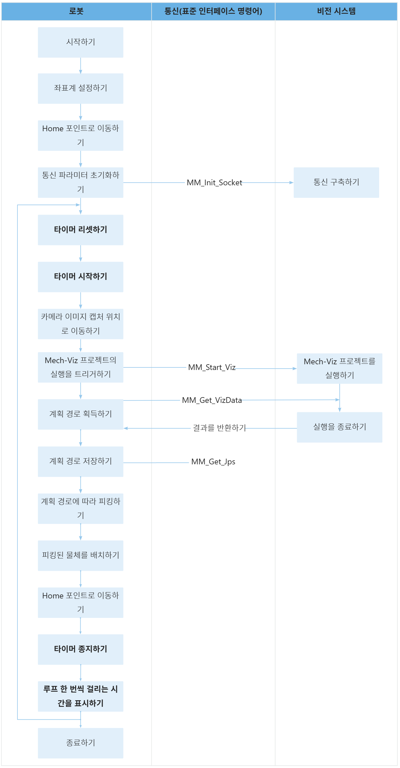
아래 표는 타이머의 기능에 대해 설명합니다.
| 워크플로 | 코드와 설명 |
|---|---|
루프를 통헤 통신을 구축부터 피킹 및 배치 작업을 완료될 때까지 소요된 시간을 계산하기 |
위 코드는 프로그램이 LOOP와 ENDLOOP 사이의 코드를 순환 실행함을 나타냅니다. 위 코드는 타이머 $TIMER[1]을 0ms로 설정하는 것을 나타냅니다. 위 코드는 타이머 $TIMER[1]이 시간을 측정하기 시작함을 나타냅니다. 위 코드는 타이머 $TIMER[1]이 시간을 측정하기 완료함을 나타냅니다.
위 코드는 SWRITE 명령어를 통해 타미머 $TIMER[1]이 측정한 시간을 "time: %d ms" 형식으로 배열에 씁니다. 위 코드는 측정된 시간을 티치 펜던트 화면에 표시하는 것을 나타냅니다. |