样例程序11:MM_S11_Viz_Timer
程序简介
功能说明 |
机器人通过计时器计算每次从建立通信到完成抓取与放置所花费的时间。 |
||
文件路径 |
Mech-Vision和Mech-Viz软件安装目录下
|
||
所需工程 |
Mech-Vision工程和Mech-Viz工程 |
||
使用前提 |
|
| 此样例程序仅是示例程序。用户需根据实际情况在此基础上进行修改,请勿直接使用该程序。 |
程序解读
以下为MM_S11_Viz_Timer样例程序的代码及相关解释说明。
| 与MM_S2_Viz_Basic样例相比,本样例仅新增了计时器的功能(加粗部分的代码)。因此,下文不再重复解释与MM_S2_Viz_Basic样例相同部分的代码(详情请参考MM_S2_Viz_Basic样例说明)。 |
MODULE MM_S11_Viz_Timer
!----------------------------------------------------------
! FUNCTION: trigger Mech-Viz project and get planned path,
! add a timer to record cycle time
! Mech-Mind, 2023-12-25
!----------------------------------------------------------
!define local num variables
LOCAL VAR num pose_num:=0;
LOCAL VAR num status:=0;
LOCAL VAR num toolid{5}:=[0,0,0,0,0];
LOCAL VAR num vis_pose_num:=0;
LOCAL VAR num count:=0;
LOCAL VAR num label{5}:=[0,0,0,0,0];
LOCAL VAR clock timer;
LOCAL VAR num timer_val;
!define local joint&pose variables
LOCAL CONST jointtarget home:=[[0,0,0,0,90,0],[9E+9,9E+9,9E+9,9E+9,9E+9,9E+9]];
LOCAL CONST jointtarget snap_jps:=[[0,0,0,0,90,0],[9E+9,9E+9,9E+9,9E+9,9E+9,9E+9]];
LOCAL PERS robtarget camera_capture:=[[302.00,0.00,558.00],[0,0,-1,0],[0,0,0,0],[9E+9,9E+9,9E+9,9E+9,9E+9,9E+9]];
LOCAL PERS robtarget drop_waypoint:=[[302.00,0.00,558.00],[0,0,-1,0],[0,0,0,0],[9E+9,9E+9,9E+9,9E+9,9E+9,9E+9]];
LOCAL PERS robtarget drop:=[[302.00,0.00,558.00],[0,0,-1,0],[0,0,0,0],[9E+9,9E+9,9E+9,9E+9,9E+9,9E+9]];
LOCAL PERS jointtarget jps{5}:=
[
    [[11.1329,49.0771,-36.9666,0.5343,79.2476,-169.477],[9E+9,9E+9,9E+9,9E+9,9E+9,9E+9]],
    [[11.2355,52.1281,-23.3996,0.5938,62.6295,-169.548],[9E+9,9E+9,9E+9,9E+9,9E+9,9E+9]],
    [[11.1329,49.0771,-36.9666,0.5343,79.2476,-169.477],[9E+9,9E+9,9E+9,9E+9,9E+9,9E+9]],
    [[11.1329,49.0771,-36.9666,0.5343,79.2476,-169.477],[9E+9,9E+9,9E+9,9E+9,9E+9,9E+9]],
    [[0,0,0,0,90,0],[9E+9,9E+9,9E+9,9E+9,9E+9,9E+9]]
];
!define local tooldata variables
LOCAL PERS tooldata gripper1:=[TRUE,[[0,0,0],[1,0,0,0]],[0.001,[0,0,0.001],[1,0,0,0],0,0,0]];

PROC Sample_11()
    !set the acceleration parameters
    AccSet 50, 50;
    !set the velocity parameters
    VelSet 50, 1000;
    !move to robot home position
    MoveAbsJ home\NoEOffs,v3000,fine,gripper1;
    !initialize communication parameters (initialization is required only once)
    MM_Init_Socket "127.0.0.1",50000,300;
LOOP:
    !reset timer to 0
    ClkReset timer;
    !start timer
    ClkStart timer;
    !move to image-capturing position
    MoveL camera_capture,v1000,fine,gripper1;
    !open socket connection
    MM_Open_Socket status;
    IF status=3099 THEN
        TPWrite "MM: Communication Error";
        Stop;
    ENDIF
    !trigger Mech-Viz project
    MM_Start_Viz 2,snap_jps,status;
    IF status<>2103 THEN
        !add error handling logic here according to different error codes
        TPWrite "MM: Status Error";
        STOP;
    ENDIF
    !get planned path, 1st argument (1) means getting pose in JPs
    MM_Get_VizData 1, pose_num, vis_pose_num, status;
    !check whether planned path has been got from Mech-Viz successfully
    IF status <> 2100 THEN
        !add error handling logic here according to different error codes
        !e.g.: status=2038 means no point cloud in ROI
        Stop;
    ENDIF
    !close socket connection
    MM_Close_Socket;
    !save waypoints of the planned path to local variables one by one
    MM_Get_Jps 1,jps{1},label{1},toolid{1};
    MM_Get_JPS 2,jps{2},label{2},toolid{2};
    MM_Get_JPS 3,jps{3},label{3},toolid{3};
    !follow the planned path to pick
    !move to approach waypoint of picking
    MoveAbsJ jps{1},v1000,fine,gripper1;
    !move to picking waypoint
    MoveAbsJ jps{2},v300,fine,gripper1;
    !add object grasping logic here, such as "setdo DO_1, 1;"
    Stop;
    !move to departure waypoint of picking
    MoveAbsJ jps{3},v1000,fine,gripper1;
    !move to intermediate waypoint of placing
    MoveJ drop_waypoint,v1000,z50,gripper1;
    !move to approach waypoint of placing
    MoveL RelTool(drop,0,0,-100),v1000,fine,gripper1;
    !move to placing waypoint
    MoveL drop,v300,fine,gripper1;
    !add object releasing logic here, such as "setdo DO_1, 0;"
    Stop;
    !move to departure waypoint of placing
    MoveL RelTool(drop,0,0,-100),v1000,fine,gripper1;
    !move back to robot home position
    MoveAbsJ home\NoEOffs,v3000,fine,gripper1;
    !stop timer
    ClkStop timer;
    !read timer value and display the cycle time in log message on teach pendant
    timer_val:=ClkRead(timer);
    TPWrite "single cycle time: "numtostr(timer_val,3)"s.";
    GOTO LOOP;
ENDPROC
ENDMODULE
上述样例程序代码对应的流程如下图所示。
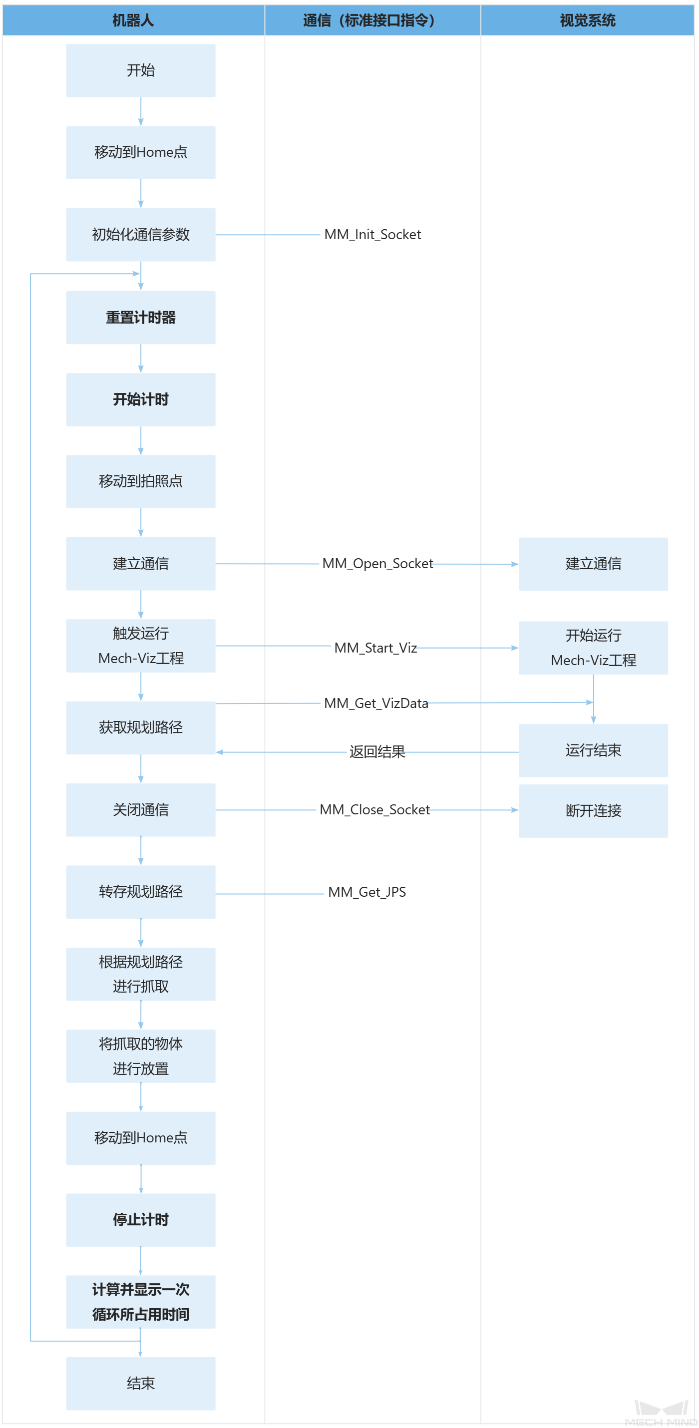
下表为计时器的逻辑解读。
| 流程 | 代码及说明 |
|---|---|
通过循环计算每次从建立通信到完成抓取与放置所花费的时间 |
上述代码表示,程序循环执行LOOP与GOTO LOOP之间的代码。 上述代码表示,将计时器timer重置为0。 上述代码表示,计时器timer开始计时。 上述代码表示,计时器timer结束计时。 上述代码表示,通过ClkRead指令读取计时器timer计算的时间(即每次从建立通信到完成抓取与放置所花费的时间),然后将时间值赋值给timer_val变量。
因此,整条语句表示,将计算的时间显示在示教器屏幕上。 |