Deploy Drift Correction Feature in Solution
This section provides instructions on deploying the drift correction feature in the solution of an EIH vision system.
Deployment Process Overview
The deployment process of this feature is shown below.

-
Learn about the deployment prerequisites: Learn about the prerequisites for the deployment of “Auto-correct accuracy drift in EIH vision system” in the solution.
-
Complete the preparations: Prepare all the necessary materials.
-
Collect workstation data: Collect the calibration board poses on different target object layers, facilitating the calculation of required image-capturing points.
-
Fasten calibration spheres: Based on the calibration board’s location and the recommended robot flange pose, determine the recommended locations to fasten the calibration spheres, and fasten the calibration spheres as required.
-
Validate image-capturing points: Calculate the repeatability of calibration sphere poses from each image-capturing point to ensure accurate and reliable data for accuracy drift correction.
-
Enable auto-correction: Enable the auto-correction feature in the picking project. Then write and run the robot auto-correction program to correct the accuracy drift of the vision system during production.
-
Check deployment result: Check the deployment result of the “Auto-correct accuracy drift in EIH vision system” feature in the solution.
Deployment Prerequisites
The following prerequisites should be met before proceeding with the deployment:
-
Ensure that the vision solution for picking has been deployed for the workstation.
-
Ensure that the camera, robot, and extrinsic parameter accuracy checks have been completed, and that the robot is able to pick target objects successfully. Please refer to Error Analysis Tool for specific instructions.
-
Ensure that space has been reserved at the workstation for fastening the calibration spheres.
Preparations
If all the prerequisites can be met, you can start to prepare the materials.
-
Prepare the calibration board.
-
Check the materials. Open the EIH kit packaging box, and ensure it contains calibration spheres, mounting brackets, and other components.
-
Warm up the camera in advance. If the new camera is in a cold-start state, its intrinsic parameter accuracy may change due to temperature increases during image acquisition. Therefore, the camera should be warmed up in advance. Please refer to Warm Up for detailed instructions.
Start Deployment
After completing the above deployments, you can go to the menu bar and select to enter the tool. Then click the Start deployment button in the lower right corner to start the deployment.
Collect Workstation Data
This step automatically calculates the image-capturing points for calibration spheres by collecting the workstation data.
Connect to a Camera
-
Click the Select camera button to select the camera used in the picking project.
-
Select the picking project in which the accuracy drift should be corrected and the corresponding calibration parameter group and configuration parameter group.
Check Site Condition
Select the calibration board model you use and confirm the calibration sphere fastening status.
|
If “Fastened” is selected, you will only need to set the diameter of the calibration sphere in the “Fasten calibration spheres” step. |
Locate Calibration Board
After completing the above steps, please locate the calibration board according to the illustration and requirements below and collect the calibration board poses of each target object layer in the workstation.
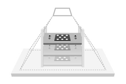
|
To ensure accurate calibration board localization, it is necessary to ensure that there is only one calibration board in the camera’s field of view. |
If the target objects are arranged neatly, click here to learn how to locate the calibration board.
-
Place the calibration board at the center of the highest target objects are located.
For large target objects, the calibration board should be placed on the specific features of the object, namely the areas used for point cloud model matching.
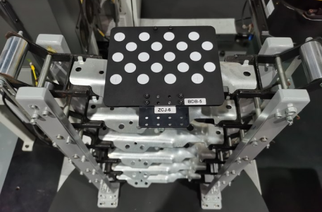
-
Move the robot to the image-capturing point above the target object layer. This image-capturing point must be the same as the one used in the actual production process.
-
Click + Add to add a new target object layer.
-
Click Locate to capture an image of the calibration board on the current target object layer.
If the localization succeeds, the message Located successfully will occur. Click View image to check the successfully located calibration board, as shown below.
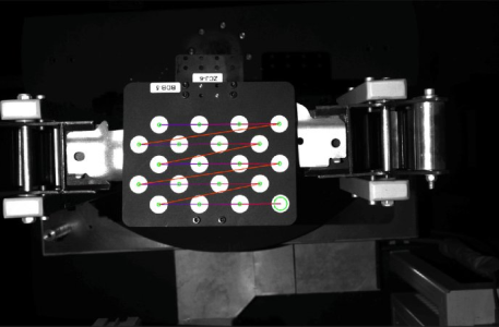
If the localization fails, the message Failed to locate will occur. You can click Outline calibration board to outline the calibration board in the pop-up window, or try again after adjusting the camera parameter group.
-
Place the calibration board on the second, third and subsequent layers, and repeat the above steps until information on all target object layers is collected.

If the target objects are stacked randomly, click here to learn how to locate the calibration board.
-
Place the calibration board at the center of the layer where the lowest target objects are located.
For large target objects, the calibration board should be placed on the specific features of the object, namely the areas used for point cloud model matching.
-
Move the robot to the image-capturing point above the target object layer. This image-capturing point must be the same as the one used in the actual production process.
-
Click + Add to add a new target object layer.
-
Click Locate to capture an image of the calibration board on the current target object layer.
If the localization succeeds, the message Located successfully will occur. Click View image to check the successfully located calibration board, as shown below.
If the localization fails, the message Failed to locate will occur. You can click Outline calibration board to outline the calibration board in the pop-up window, or try again after adjusting the camera parameter group.
-
Place the calibration board 20 cm above the previously located target object layer and locate the calibration board again.
-
Repeat the above steps until information on all target object layers within the height range is collected.

After the workstation data is collected, click Nextto fasten calibration spheres.
Fasten Calibration Spheres
In this step, the recommended locations to fasten the calibration spheres can be obtained based on the calibration board’s location and the recommended robot flange pose. Then you should fasten the calibration spheres as required.
Place Calibration Board
-
Place the calibration board according to the requirements.
Place the calibration board on the area where the calibration spheres will be arranged according to the following requirements.
-
Ensure that the area for placing the calibration board is within the robot’s reachable range and that the robot will not collide with surrounding objects.
-
Place the calibration board horizontally with its front side up and leave space around it for calibration spheres.
-
Typically, an object is needed to support the calibration board from the bottom, ensuring that the calibration board is as level as possible with the center of the sphere.
-
No obstacles should be present above the calibration board to ensure the robot can move freely over it.

-
-
Locate the calibration board.
Move the robot to bring the camera to an appropriate height, ensuring that the calibration board is clearly visible within the camera’s field of view and at the center of the field of view, and then click Locate.
-
After the localization succeeds, the message Located successfully will occur on the left side of the Locate button, and the image of calibration board will be displayed. At this time, the current robot flange pose should be entered into the frames on the interface.
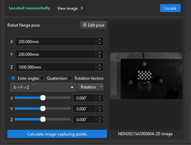
It is necessary to check the Euler angle convention, ensuring the selection is right.
-
If the localization fails, the message Failed to locate will occur on the left side of the Locate button. You can click Outline calibration board to outline the calibration board in the pop-up window.
-
-
Calculate the image-capturing points.
When the calibration board is located successfully, click Calculate image-capturing points to automatically calculate the image-capturing points, i.e. the robot flange poses during image capturing.
Fasten Calibration Spheres
|
If the calibration sphere is fastened according to the on-site situation during the “Collect workstation data” step, you only need to set the diameter of the calibration sphere in this step. |
-
Move the robot.
After a number of robot flange poses are obtained in the “Arrange calibration board” step, the nearest robot flange pose to the calibration board will be displayed on the current page as the recommended value. Then move the robot to the recommended pose for subsequent continuous image acquisition of the calibration spheres.
Please ensure that no collisions occur during the robot’s movement to this pose. It is recommended to jog the robot to the target pose at a low speed and observe whether there will be any collisions.
If there is a possibility of collision in the robot path, the image-capturing point can be lifted appropriately, but it is necessary to ensure that the image-capturing point is lifted within 100 mm. If the lifting distance exceeds 100 mm, a supportive base should be added beneath the calibration sphere.

-
Set the dimensions of the calibration sphere.
Set the diameter of the calibration sphere according to the actual calibration sphere.

-
Fasten the calibration spheres.
Click Capture continuously and fasten the calibration spheres at the recommended positions (in the green dots).
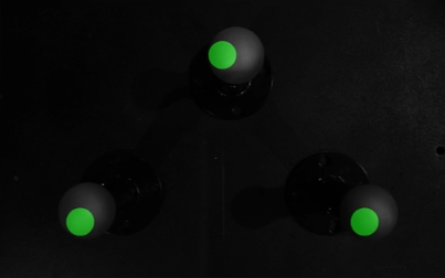
-
Please fasten the calibration spheres on the ground.During actual production, avoid accidentally touching the calibration spheres.
-
You can use a marker to draw lines between the calibration sphere and its mount as a reference for checking whether their relative positions have changed later.
-
After you fasten the calibration sphere, click Confirm fastening.
-
When the calibration sphere is fastened, click Next to validate image-capturing points for calibration spheres.
Validate Image-capturing Points
This step calculates the repeatability of calibration sphere poses from each image-capturing point to ensure accurate and reliable data for accuracy drift correction.
-
Move the robot to the flange pose corresponding to the image-capturing point and manually record the pose in the robot program.
Please ensure that no collisions occur during the robot’s movement to this pose. It is recommended to jog the robot to the target pose at a low speed and observe whether there will be any collisions.
If there is a possibility of collision in the robot path, the image-capturing point can be lifted appropriately, but it is necessary to ensure that the image-capturing point is lifted within 100 mm. If the lifting distance exceeds 100 mm, a supportive base should be added beneath the calibration sphere.
-
Click Outline and validate to outline the calibration spheres at each image-capturing point, and then click Validate.
The ROI must fully enclose the calibration sphere, leaving a margin equal to the sphere’s diameter on all sides (top, bottom, left, and right). If “Failed to locate” occurs after setting the ROI, please check whether the calibration sphere diameter set in the “Collect workstation data” step is correct.
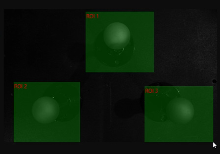
After validating all image-capturing points, click the Save button to save the deployment. Now projects for drift correction will be automatically generated in the current solution.
-
Drift_Collection_EIH: This project collects the calibration sphere poses at each image-capturing point.
-
Drift_Calculation: The project generates the drift correction data based on the calibration sphere poses collected by the “Drift_Collection_EIH” project.
|
Do not modify the two drift correction projects or any related parameters. At the same time, during subsequent drift correction processes, ensure that the names and numbers of the drift correction projects remain unchanged. When the drift correction projects are generated, a point cloud model of the calibration sphere will be automatically generated in the target object editor as well. Please do not modify the name or other configuration of this point cloud model. |
Enable Auto-Correction
After validating the image-capturing points, you should perform the following steps to correct the accuracy drift in the actual production process.
-
Enable the auto-correction feature in the picking project.
-
Write a robot auto-correction program to automatically collect calibration sphere poses and generate the drift correction data.
Enable Auto-Correction in Picking Project
After the above deployment, select the “Auto-Correct Accuracy Drift in Vision System” parameter of the “Output” or “Path Planning” Step in the picking project to enable the auto-correction feature.
Write Robot Program
Writing a robot auto-correction program is used to automatically collect calibration sphere poses and generate the drift correction data. You will need the manually recorded robot flange poses while writing the program. If you have not recorded the robot flange poses, click the Finish to return to the tool’s home page. Then, click the Check deployment button at the bottom to check the flange poses corresponding to the image-capturing points in the deployment result.
|
On the home page of the tool, you can also hover your mouse over |
Based on the following program workflow explanation and FANUC robot example program, you can write your own robot auto-correction program. The basic workflow of the robot auto-correction program is as follows.
Step 1: Determine the robot reference frame and tool reference frame.
Step 2: Move the robot to a safe position.
Step 3: Move the robot to the calculated image-capturing point 1.
Step 4: Once the robot reaches the image-capturing point 1, switch the parameter recipe in the project for collecting calibration sphere poses (Drift_Collection_EIH) to the one corresponding to the image-capturing point.
Step 5: Once the parameter recipe is switched, trigger the “Drift_Collection_EIH” project to run and collect the calibration sphere poses at image-capturing point 1.
Step 6: Follow steps 3 to 5 for image-capturing points on other layers to collect the calibration sphere poses at each point.
Step 7: After completing the pose collection for all image-capturing points, switch the parameter recipe of the project for generating drift correction data (Drift_Calculation).
Step 8: Trigger the “Drift_Calculation” project to run and generate the drift correction data.
Step 9: Move the robot to a safe position.
The following auto-correction program, developed based on the workflow outlined above, uses a FANUC robot. In this example program, the number of image-capturing points for the calibration sphere is 2, the index of the project for collecting the calibration sphere poses is 2, and the index of the project for generating drift correction data is 3.
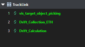
   UFRAME_NUM=0 ;
   UTOOL_NUM=1 ;
 J P[1] 100% FINE ;
   CALL MM_INIT_SKT('8','192.168.10.22',50000,5) ;
 L P[2] 1000mm/sec FINE ;
   WAIT   2.00(sec) ;
   CALL MM_SET_MOD(2,1) ;
   CALL MM_START_VIS(2,0,2,10) ;
   WAIT   1.00(sec) ;
 L P[3] 1000mm/sec FINE ;
   WAIT   2.00(sec) ;
   CALL MM_SET_MOD(2,2) ;
   CALL MM_START_VIS(2,0,2,10) ;
   WAIT   1.00(sec) ;
   CALL MM_SET_MOD(3,1) ;
   CALL MM_START_VIS(3,0,2,10) ;
   J P[1] 100% FINE ;
   END ;
Key statements in the auto-correction program are summarized in the following table.
|
This table only explains the key statements; for detailed explanations of each statement in the FANUC robot auto-correction program, refer to the example program for FANUC robots. |
| Workflow | Code and description | ||
|---|---|---|---|
Set the reference frame |
Define the world reference frame as the robot reference frame and the flange reference frame as the tool reference frame. |
||
Move the robot to the Home position |
Move the robot to the Home position where the robot is away from target objects and the surrounding equipment.
|
||
Initialize communication parameters |
Set the robot port number to 8, with the IP address of the IPC set to 192.168.10.22. The port number used for communication between the IPC and the robot is 50000, and the timeout period is 5 minutes. |
||
Move the robot to the image-capturing point 1 |
The robot moves to the image-capturing point 1 in linear motion, with a velocity of 1000 mm/sec. You can check the information of this image-capturing point in the deployment result. |
||
Switch the parameter recipe of the project for collecting the calibration sphere poses |
Switch the parameter recipe of the project for collecting calibration sphere poses (Drift_Collection_EIH) to parameter recipe 1. |
||
Trigger the project for collecting calibration sphere poses |
Trigger the Drift_Collection_EIH project to collect calibration sphere poses at each image-capturing point. |
||
Switch the parameter recipe of the project for generating the drift correction data |
After collecting calibration sphere poses at all image-capturing points, switch the parameter recipe of the project for generating drift correction data (Drift_Calculation) to parameter recipe 1.
|
||
Trigger the project for generating the drift correction data to run |
Trigger the “Drift_Calculation” project to run and generate drift correction data based on the collected calibration sphere poses. |
||
Move the robot to the Home position |
Move the robot to the Home position where the robot is away from target objects and the surrounding equipment. |
Load Program Files to Robot
After writing the robot auto-correction program, you can load the program to the robot.
|
According to the robot brand used in your project, you can load the robot auto-correction program by referring to the “Set up Standard Interface Communication” guide for the corresponding robot brand in Standard Interface Communication. |
Test Robot Program
Run the robot auto-correction program after loading it to the robot. After running the program, the robot will move to the corresponding image-capturing points. Then the program will trigger the Mech-Vision project to run, capture images of the calibration spheres, and collect the poses of the calibration spheres. The generated drift correction data is then used to correct accuracy drift.
|
According to the robot brand used in your project, you can select and test the robot auto-correction program by referring to the “Set up Standard Interface Communication” guide for the corresponding robot brand in Standard Interface Communication. |
After running the robot auto-correction program, correction records will be generated and can be viewed on the Data monitoring dashboard.
Test Picking the Target Objects
Run the robot picking program. If the robot can accurately pick the target object, the deployment is considered successful.
Note that after the test picking is complete, to ensure long-term stability in actual production, you must configure the alert threshold in the Data monitoring dashboard. The threshold is typically recommended to be set at 10 mm. If the drift compensation exceeds this threshold, verify that the camera and robot tool are securely mounted and ensure the robot’s zero position is accurate.
Determine the Correction Cycle
Based on the actual conditions on-site, run the robot auto-correction program periodically (either manually or automatically) to regularly collect calibration sphere poses, enabling periodic correction of accuracy drift of the vision system.
Now you have completed the deployment of “Auto-correct accuracy drift in EIH vision system” in the solution. Click the Finish button to return to the tool’s home page.
|
After deployment, it is recommended to export the current configuration parameter group of the camera to a local backup. This ensures that if the camera is damaged and needs to be replaced, the configuration parameter group can still be retrieved. |
|
After deployment, you can click the View deployment button at the bottom of the tool’s home page to check the deployment results. The deployment result includes the IDs of the cameras with the drift correction feature deployed, the save path for the deployment result, the image-capturing point information, and the camera No. recipe. 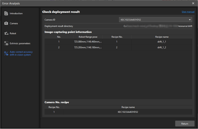
|