Index
Basic Pallet Settings
Motion Control
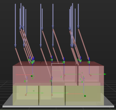
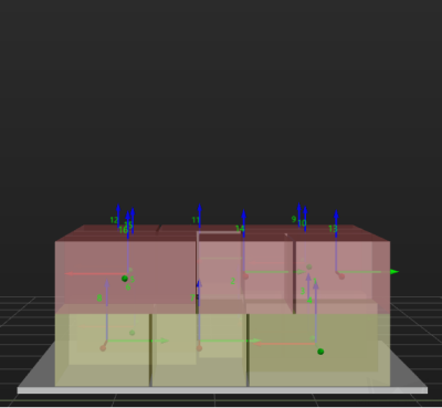
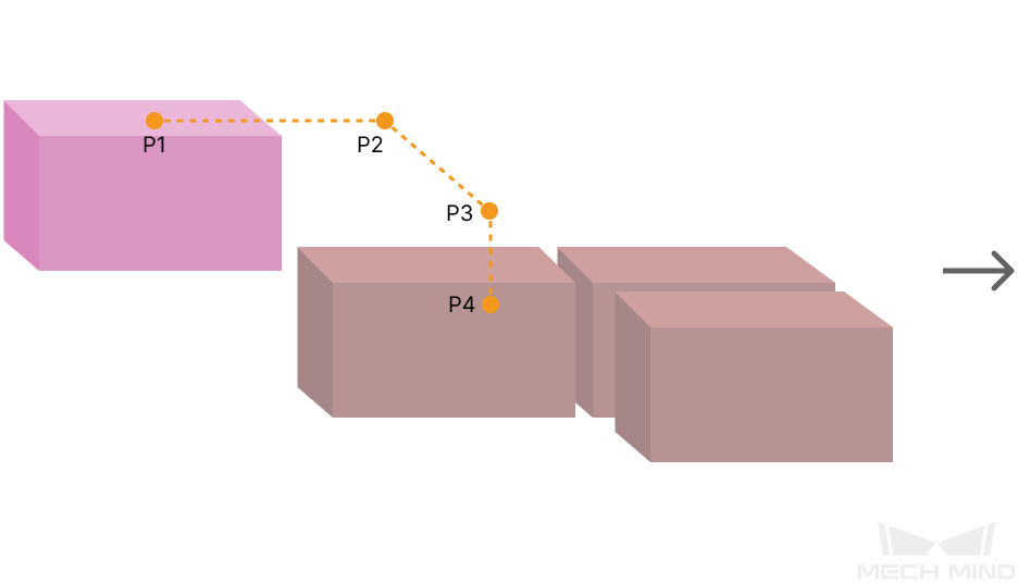
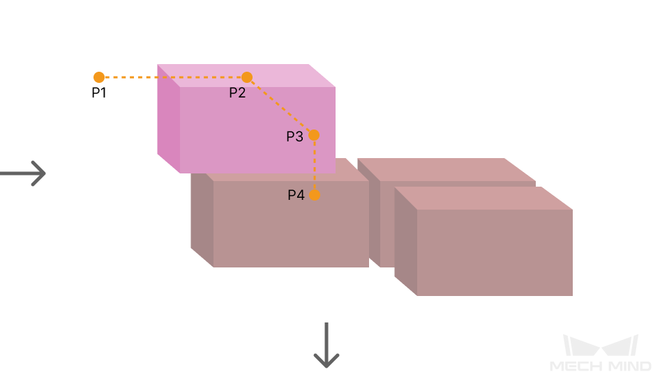
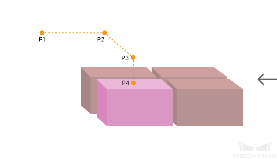
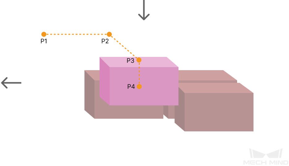
Some of the trajectories during box palletization are shown in the figure below.
|
|
|
|
Among them,
-
P1: middle point; P2: entry point; P3: adjustment point; P4: placement point.
-
P1-P2: entry section; P2-P3: adjustment section; P3-P4: placement section.
Auto Middle Point Force MoveJ
The path between the move waypoint before this Step and the middle point (P1) is the middle point force.
Selected by default. This is a joint move.
Entry Force MoveJ/Adjust Force MoveJ/Place Force MoveJ
Unselected by default. This is a linear move.
This parameter will not be selected when palletizing in a site where the operation space is small and the linear move is required. As linear move may lead to singularity problems, you can set joint move in entry section / adjustment section / placement section selectively.
Acc&Vel Scale Ratio
This parameter is mainly used to slow down the robot during the placement process to ensure a more stable placement of the boxes.
-
The velocity (acceleration) of the entry section is the same as the set velocity (acceleration) in the “Basic Move Settings.”
-
The velocity (acceleration) of the adjustment section and placement section: the velocity (acceleration) of the entry section ✖ this parameter (Acc&Vel Scale Ratio).
Entry Adjust
The three parameters together determines the path along which the robot enters the stack area. Adjust the entry path to make the held box approaches the palletized boxes at a specified angle, and then the held box will be placed vertically. If the box is directly placed on the stack in a vertical path, collisions may occur between the robot, held box, and the palletized boxes possibly due to accuracy and other factors.
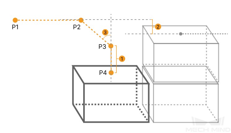
For each box, there are four points to enter the stack area. This parameter determines three points: entry point (P2); adjustment point (P3); and placement point (P4).
|
1: Vertical Adjust Length; 2: Vertical Margin; 3: Entry Angle Z |
| Parameter | Description |
|---|---|
Vertical Adjust Length Ratio |
As shown in the right figure, vertical adjust length ratio = vertical adjust length (1) / the height of the box. |
Value range: 0–1; recommended value: 50%. |
|
Vertical Margin |
As shown in the right tag 2. |
Value range: 0–+∞; unit: mm; the specified values depend on different application scenarios. |
|
Entry Angle Z |
As shown in the right tag 3. |
Value range: -80°–80°; recommended value: 30°–45°. |
Auto Middle Point
The Auto Middle Point is the direction indication of entering into the stack area, not the actual point reached by the robot. To avoid squeezing and collisions during the placement of boxes, the auto middle point should be as far away from the pallet as possible to ensure adequate safety spacing.
Minimum Height Z
The minimum height in the Z-direction of the robot entering into the entry section (the purple path).
Maximum Height Z
The maximum height in the Z-direction of the robot entering into the entry section (the purple path).
Is Middle Point Traj Vertical
|
|
Unselected by default, i.e., the robot will approach the stack from the auto middle point. |
After selecting, the robot will approach the stack in a direction perpendicular to the pallet. |
Extended Distance For Entry
This parameter is used to extend the distance for entry.
When the tool is larger than the object being picked, the default entry path may not be long enough, resulting in a collision between the tool and placed boxes. In this case, extending the distance for entry can improve safety, avoiding the collision between the robot and placed boxes or other barriers in the process of robot movement.
Adjust Pallet via Vision
Select “Need Adjust Pallet Pose” and then set the “Vision Service Name” to apply a vision project for the stack recognition, thus adjusting the pallet dynamically.
When the project runs this Step, the software will execute the corresponding vision project and update the position of the pallet based on the vision result.
