System Hardware Setup
System hardware setup means integrating hardware devices (camera and IPC) into the actual working environment to support normal operation of the inline measurement system.
In this phase, you need to complete installation and connection of inline measurement system hardware as shown below.
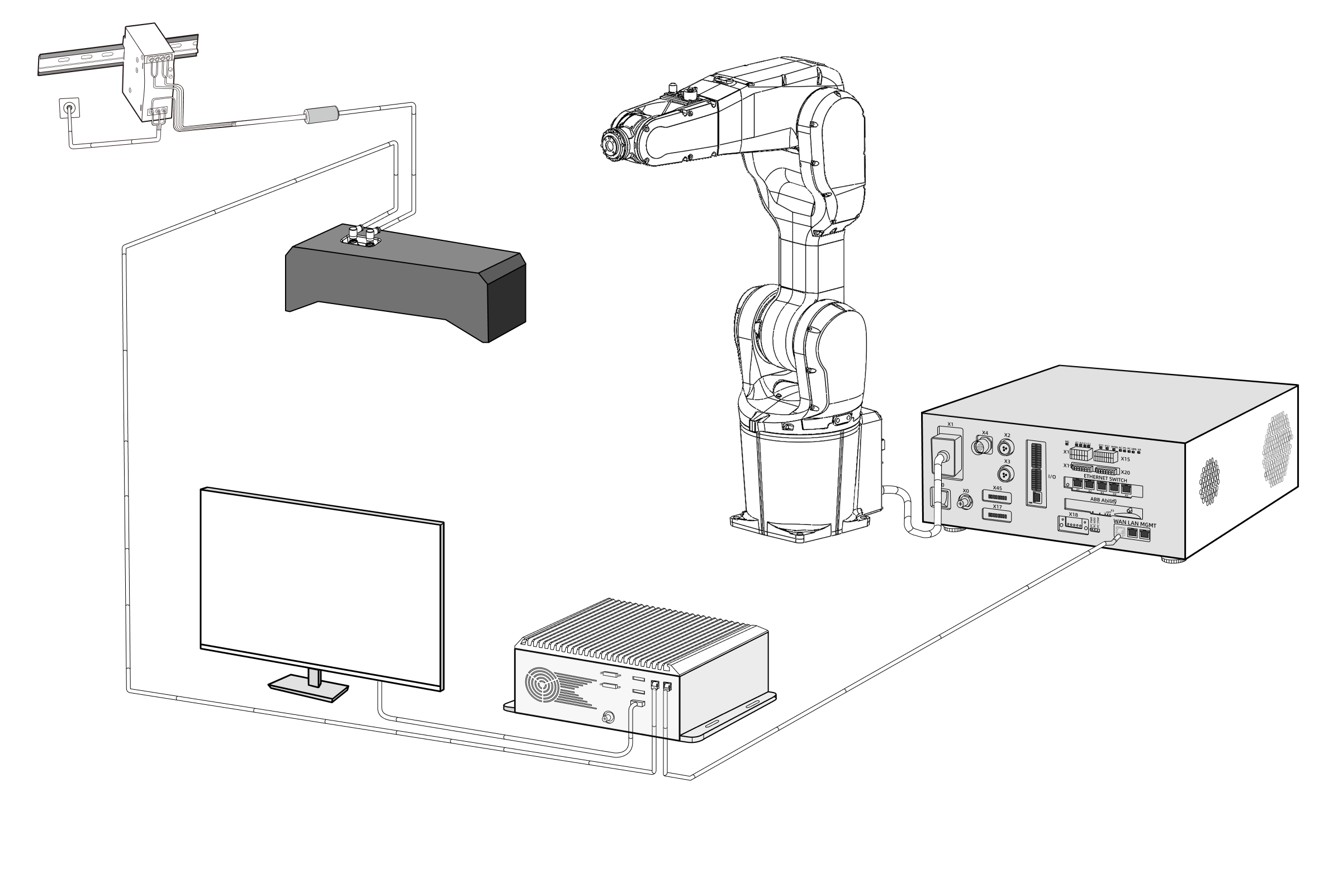
To build a Mech-Mind inline measurement system, complete the following process in order: Unpacking check → Hardware installation → Network connection → Software upgrade (optional) → Confirm that the inline measurement system can acquire images normally.
Unpacking Check
-
After receiving the camera package box, confirm that the package box is intact and undamaged.
-
Find the Packing List in the package box and check against it to ensure no items or accessories are missing or damaged.
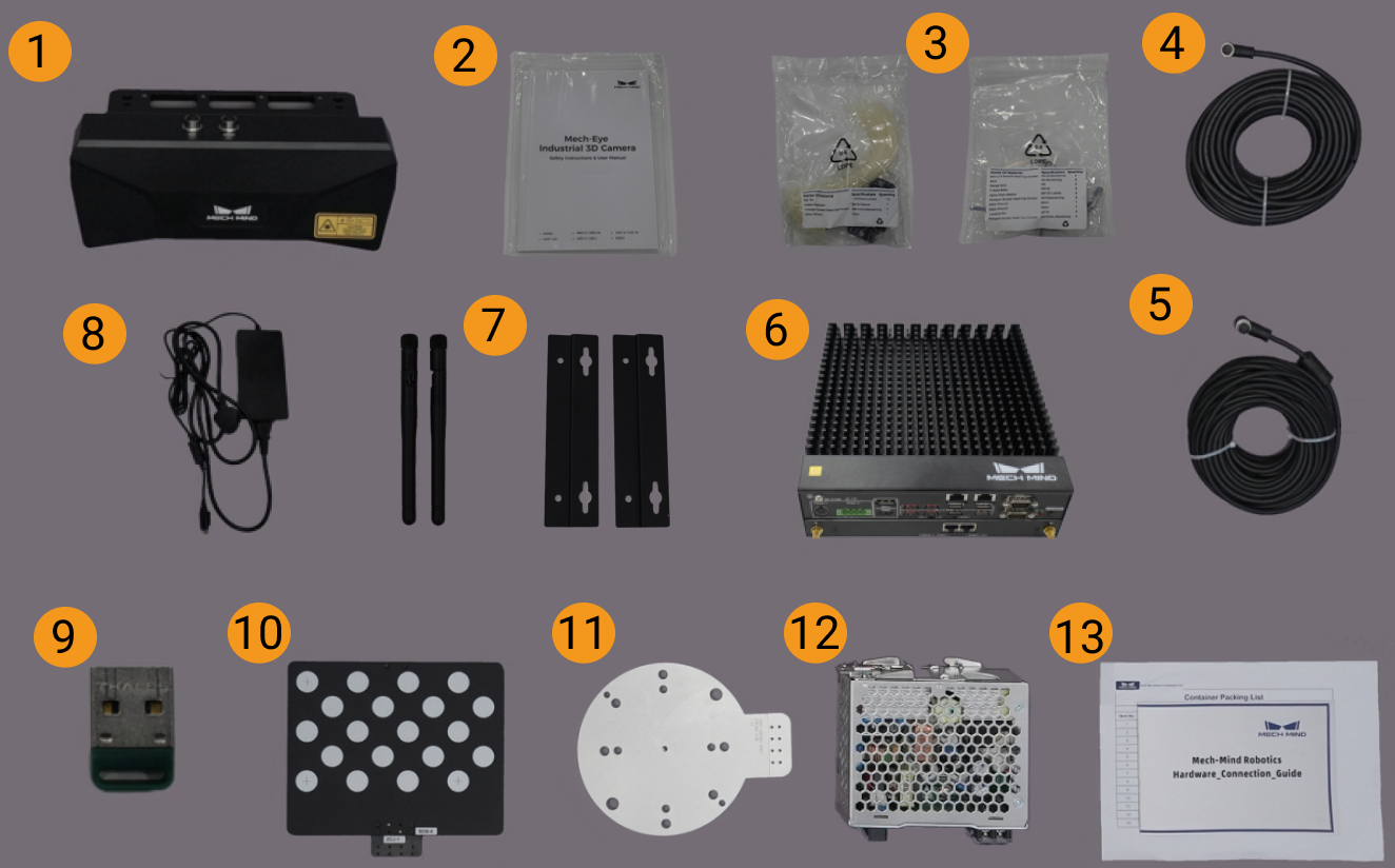
The image below shows an example of items and accessories in the camera package box for reference only. Use the actual Packing List in your package box as the standard.
| No. | Category | Name | Function |
|---|---|---|---|
1 |
Camera and accessories |
Mech-Eye Industrial 3D Camera |
Acquire images |
2 |
Camera user manual and technical specifications |
Mech-Eye Industrial 3D Camera user manual and technical specifications |
|
3 |
Camera accessory kit |
Install camera |
|
4 |
Camera DC power cable |
Connect camera to DIN rail power supply; camera power cables of different lengths can be selected as needed |
|
5 |
Camera network cable |
Connect camera to IPC; camera network cables of different lengths can be selected as needed |
|
6 |
IPC and accessories |
Mech-Mind IPC STD |
Provides runtime environment for Mech-Mind software |
7 |
IPC accessories |
IPC accessories, such as mounting brackets and external Wi-Fi antenna |
|
8 |
IPC power cable and adapter |
Power the IPC |
|
9 |
Project accessories |
USB license dongle |
Software licensing |
10 |
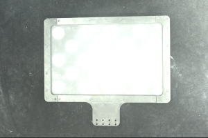
Calibration board |
Calibrate camera |
|
11 |
Flange plate |
Connect calibration board |
|
12 |
DIN rail power supply (optional) |
Power the Mech-Eye industrial 3D camera |
|
13 |
Packing list |
Lists all items and accessories in the package |
|
|
If any item is damaged or missing, contact Mech-Mind. |
Prepare Additional Materials
In addition to items in the camera package box, prepare the materials in the table below.
| Material | Function |
|---|---|
Display |
Provides a screen for the IPC |
HDMI cable |
Connects the IPC and display |
RJ45 network cable |
Connects the IPC and robot controller |
| The IPC and robot controller are usually connected directly by RJ45 cable, and the IPC and camera are usually connected directly by camera network cable. You can also use a router to connect IPC and robot controller, and IPC and camera. |
Install Hardware
Install Camera
| In the inline measurement system, the camera is usually mounted at the robot end effector, that is, using Eye in Hand (EIH). Under EIH installation, a mounting bracket is required to install the camera at the robot end. |
Refer to Design and Installation of Eye in Hand Mounting Bracket to install the camera bracket. Install the camera only after the bracket is firmly installed.
-
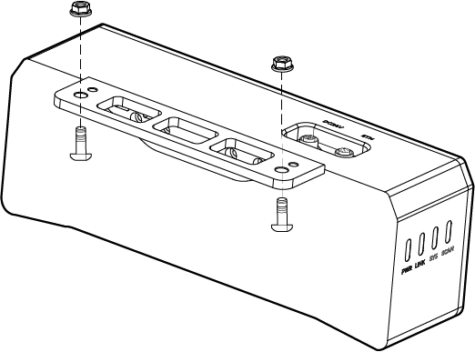
Find camera mounting screws and wrench in the camera accessory kit.
-
Tighten two nuts with the wrench to fix the camera, as shown below.
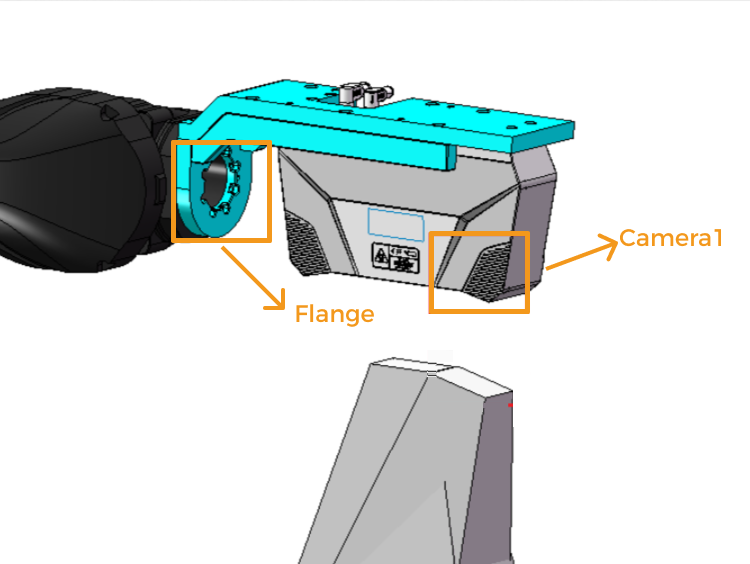
For the UHP-140-GL camera, Camera1 should be installed on the far side of the flange to ensure measurement performance, as shown below:
-
After camera installation is complete, remove the lens protective film.
-
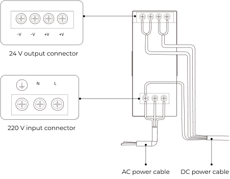
Connect camera power through DIN rail power supply.
-
Connect the DC power cable:
-
Connect +V to +V of the 24 V output terminal.
-
Connect -V to -V of the 24 V output terminal.
-
Connect PE to the 220 V input terminal
 .
.
-
-
-
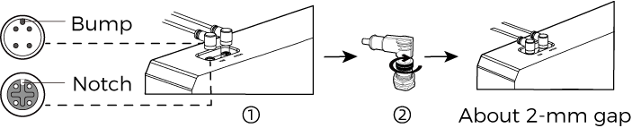
Install camera network cable.
Align the protrusion of the aviation plug on the camera network cable with the notch of the ETH port, insert it, then tighten the fastening nut.
-
Refer to Camera Cable Routing Guidelines to fix, route, and organize camera network and power cables.
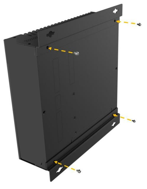
Install IPC Using Mounting Brackets
Follow these steps to fix the IPC to a wall or other flat surface with two mounting brackets.
-
Turn over this device.
-
Align fixing screw holes on both sides of the bracket with corresponding fixing screw holes on the bottom surface.
-
Insert fixing screws into the brackets to secure the device and brackets.
-
Drill holes on the planned mounting surface.
-
Align mounting holes on both sides of the brackets with drilled holes on the planned mounting surface.
-
Insert and tighten four fixing screws to secure the device to the target mounting surface.
-
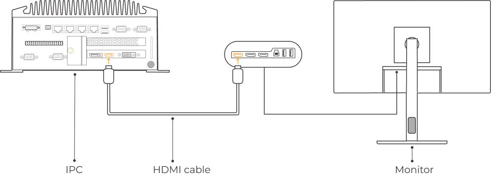
Connect IPC and display with an HDMI cable.
Insert one end of HDMI cable into the HDMI port of the display and the other end into the HDMI port of the IPC, as shown below.
-
Connect IPC power using the power adapter.
Insert the power plug of the adapter into the power port of the IPC, and connect the other end of the adapter to power.
-
Insert the dongle.
Insert the dongle into a USB port on the IPC.
-
Power on and start the IPC.
-
If the IPC starts normally, the power indicator should stay on.
-
If the IPC cannot start, contact Mech-Mind technical support.
-
Connect Network
In this section, connect IPC to camera and IPC to robot.
The following operations use the IP settings below as an example. Adjust based on your actual network environment.
| Device | IP Address | |
|---|---|---|
IPC |
Port connected to camera |
192.168.100.10 |
Port connected to robot control cabinet |
192.168.200.10 |
|
Camera |
192.168.100.20 |
|
Robot |
192.168.200.20 (already configured) |
|
|
When using two IPC network ports to connect camera and robot separately, IPs must be in different subnets. If only one port is used to connect camera and robot, connect through a switch or router, and keep all three in the same subnet. |
Connect IPC to Camera and IPC to Robot Control Cabinet
-
Insert the other end of the camera network cable into the IPC network port.
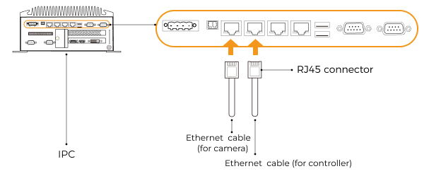
-
Use an RJ45-to-RJ45 cable: insert one end into the IPC network port and the other end into the robot control cabinet network port.
Set IPC IP Address
-
On the IPC, select to open the Network Connections page.
-
Select the network port connected to camera, right-click Rename, then rename it to indicate the network connection (for example, "To_camera").
-
Select the network port connected to camera, right-click Properties to enter the Ethernet Properties page.
-
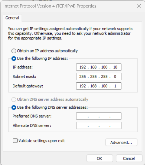
Select Internet Protocol Version 4 (TCP/IPv4) checkbox, then click Properties to open Internet Protocol Version 4 (TCP/IPv4) Properties.
-
Select Use the following IP address, set IP address to "192.168.100.10", Subnet mask to "255.255.255.0", and Default gateway to "192.168.100.1", then click OK.
-
Repeat steps 2-5. Rename the network port connected to robot control cabinet (for example, "To_robot") and set its IP address (for example, "192.168.200.10").
The IP address of the IPC network port connected to robot control cabinet must be in the same subnet as the robot IP address.
Set Camera IP Address
-
On the IPC desktop, double-click the
 icon to run Mech-Eye Viewer.
 -
Select the camera in the camera list. Move the cursor to the camera info bar. When
 appears, click it to open the IP Configuration dialog.
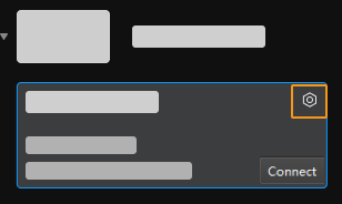
If camera search or connection fails, refer to Camera Troubleshooting.
-
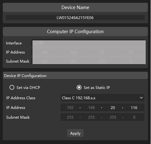
In IP Configuration, select Set as static IP and configure IP address type, IP address, and Subnet mask according to the network environment. For example, in the figure below these are set to "Type C 192.168.x.x", "192.168.20.116", and "255.255.255.0". Then click Apply.
|
The camera IP address must be in the same subnet as the IP address of the IPC network port connected to camera. |
Test Network Connectivity
-
Press Win + R to open the Run dialog.
-
Enter
cmdin Open, then click OK. -
In the command window, enter ping XXX.XXX.XX.XX and press Enter.
Replace XXX.XXX.XX.XX with the actual configured IP address of camera or robot.
If network connectivity is normal, you should receive the following reply:
Pinging XXX.XXX.XX.XX with 32 bytes of data:
Reply from XXX.XXX.XX.XX: bytes=32 time<1ms TTL=128
Reply from XXX.XXX.XX.XX: bytes=32 time<1ms TTL=128
Reply from XXX.XXX.XX.XX: bytes=32 time<1ms TTL=128
Reply from XXX.XXX.XX.XX: bytes=32 time<1ms TTL=128
Confirm Captured Image Quality
After verifying network connectivity among IPC, camera, and robot, and confirming software versions are up to date, verify that the inline measurement system can acquire images normally and that image quality meets requirements:
-
Place a calibration board in the center of the camera field of view.
-
On the IPC desktop, double-click
to launch Mech-Eye Viewer. -
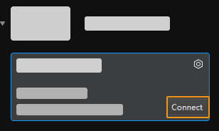
In the camera list, select camera and click Connect.
-
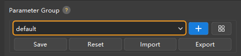
After camera connection, select a parameter group based on needs. For UHP-140-GL, set Capture Mode to Camera1 on the Parameters tab.
Starting from firmware 2.2.0, cameras include built-in parameter group templates for different scenarios or parts. After selecting the corresponding parameter group for the actual scenario, fine-tune parameter values to obtain qualified data and simplify parameter adjustment. For details, refer to Parameter Group Templates.
-
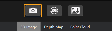
After selecting parameter group, click Capture Once.
-
Confirm captured image quality meets requirements.
-
2D image: the 2D image should be neither too bright nor too dark, and surface features of target object should be clearly visible.
Normal Overexposed Underexposed 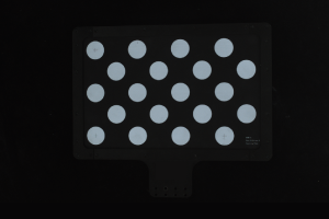
-
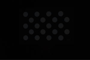
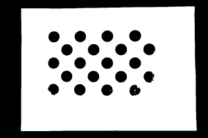
Depth map and point cloud: data corresponding to target object should be complete.
Complete Point Cloud Incomplete Point Cloud Incomplete Point Cloud 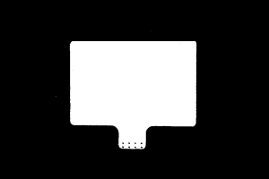
-
|