Terms and Concepts
To ensure you can understand the technical terms and professional expressions, this document compiles concept explanations scattered throughout the manual for easy reference.
Terms and Concepts
Inline Measurement Tutorial
- Inline Measurement System
-
A complete measurement system designed by Mech-Mind for deploying inline measurement solutions.
- Hardware Setup of Inline Measurement System
-
The inline measurement system hardware setup allows integration of the inline measurement system with the robot system by incorporating hardware devices (camera and IPC) into the actual working environment.
- IPC
-
An IPC is a computer intended for industrial purposes. Compared with regular computers, IPCs have higher reliability and precision standards.
- Camera Mounting Mode
-
It refers to the way that the camera is mounted in the working unit. Commonly seen mounting modes are eye to hand (ETH) and eye in hand (EIH).
- Camera Mounting Modes Supported by Inline Measurement System
-
The inline measurement system currently supports only the EIH mode.
- Robot Communication Configuration
-
Robot communication configuration completes the integration between the vision system and the robot system to ensure accurate and real-time interaction of data between the vision system and the robot side.
- Recommended Communication Modes for Inline Measurement System
-
When deploying an inline measurement solution, it is recommended to use Standard Interface communication between the inline measurement system and the robot system.
- Standard Interface Communication
-
If the Standard Interface communication is established between the vision system and an external device (such as a robot, PLC, or host computer), the external device sends Standard Interface commands to the vision system and the vision system returns data upon receiving the commands. In Standard Interface communication, you need to load the robot Standard Interface program and configuration files to the robot system and complete the Standard Interface communication-related configurations.
- Hand-Eye Calibration
-
Hand-eye calibration establishes the transformation relationship between the camera reference frame and the robot reference frame (namely, camera extrinsic parameters). It converts the object pose determined by the vision system into the pose in the robot reference frame, thus guiding the robot to perform its picking tasks accurately. The hand-eye calibration process may vary with the robot type, communication mode, camera mounting mode, and the calibration data collection method.
- Recommended Procedure for Hand-Eye Calibration in Inline Measurement System
-
In inline measurement systems, EIH is recommended as the camera mounting mode.
- Robot Program for Inline Measurement
-
This program is used to exchange data between the robot and the inline measurement system. Currently, Mech-Mind has developed inline measurement example programs for four robot brands: ABB, FANUC, KUKA, and YASKAWA.
- Teaching Measurement Position
-
Modify the position information in the inline measurement program to teach the measurement position to the inline measurement program so that the robot can move to the corresponding position for measurement.
Mech-Metrics Software Manual
Measurement Project Configuration
- Mech-Metrics Project
-
A Mech-Metrics project is a project created by the user in Mech-Metrics to maintain and manage an inline measurement project. A Mech-Metrics project contains a complete set of measurement configurations, which enables the management of the entire measurement process from part import, reference frame establishment, and measurement item configuration to data collection and analysis.
- Mech-MSR Solution and Project
-
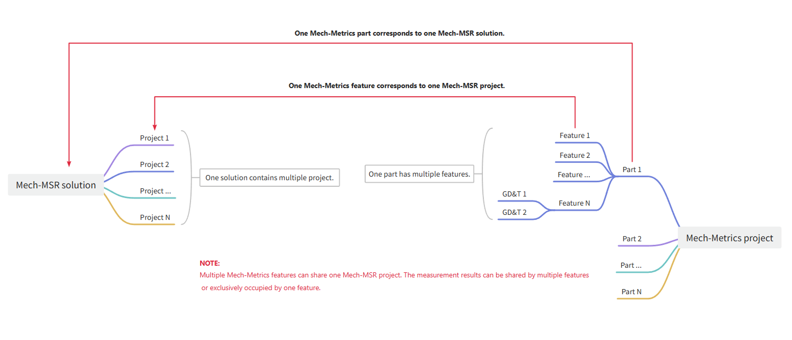
A Mech-MSR solution refers to a Mech-MSR solution specifically configured for measuring a specific part. When you use Mech-Metrics, you need to associate a part with its Mech-MSRsolution.
A Mech-MSR project is a specialized Mech-MSR project dedicated to measuring a specific feature of a part. When you use Mech-Metrics, you need to associate the feature with its Mech-MSRproject.
The correspondence between Mech-Metrics resources and Mech-MSR resources is summarized as follows:
- Part
-
A part refers to an individual workpiece that is processed or assembled during production.
A CAD model of a part refers to a digital 3D model created using CAD software to represent the shape, dimensions, and other characteristics of a part. The imported CAD model of the part represents all such parts.
Part SN (Serial Number) is the ID that uniquely identifies each part. Each part SN is unique and is usually used for product traceability, quality management, and data recording to ensure the uniqueness and traceability of each workpiece during production, inspection, and circulation.
Part IDs are identification codes used to distinguish different part types. Each part type corresponds to a unique part ID, which facilitates classification, management, and query in the system. You can configure a unique part ID for each part type according to the actual requirement. In the measurement commands (801 to 805) of the robot program, use this part ID to identify the part type.
- Fixture
-
A fixture refers to equipment, grippers, or devices used to secure and position a part, ensuring its correct location and orientation during manufacturing or assembly.
- Clamping
-
Clamping refers to the use of fixtures to hold and position a part, ensuring its correct location and orientation during manufacturing or assembly.
- Feature
-
A feature refers to specific geometric elements or attributes of a part, such as its shape, dimensions, and so on. The features that can be measured in this software include circle, slot, cylinder, point, line, plane, rectangle, pattern, distance, and angle.
- Feature ID
-
The feature ID is an integer used to uniquely identify the feature in the software. The value range is 1 to 999.
The feature ID is used to identify the feature in Command 802: Run Feature Measurement of the robot program.
- Feature Attribute
-
The software supports three types of feature attributes for measurement:
-
Point, also referred to as the center or origin.
-
Line, also referred to as the orientation or normal.
-
Surface, also referred to as the plane.
-
- Measurement Item
-
A measurement item refers to an item that you can create in the current project, for which measurement values need to be obtained through measurement. It includes features (such as circles, slots, cylinders, points, lines, planes, rectangles, patterns, distances, and angles).
- Distance
-
Distance measurement is used to measure the distance between two features. Specifically, distance measurement can be used to measure point-to-point, point-to-line, point-to-plane, line-to-line, line-to-plane, and plane-to-plane distances between two features. For example, you can select two circle features and choose the center for these two circles to measure the distance between their centers.
- Angle
-
Angle measurement is used to measure the angle between two features. Specifically, angle measurements can be used to measure the line-to-line, line-to-plane, and plane-to-plane angles between two features. For example, you can select two circle features and choose the orientation for these two circles to measure the angle between their normals.
- Control Item
-
Control items refer to the measurement children of measurement items. Control items are used to constrain measurement items. For example, the control items of a circle measurement item include dimension control items (X, Y, Z, and radius), GD&T control items (profile of a surface, parallelism, perpendicularity, position, and concentricity), and custom control items.
- GD&T
-
In this software, geometric dimensioning and tolerancing (GD&T) measurements are a type of control items developed based on GD&T. GD&T is an international standard used to define the geometric characteristics of a part. It provides a unified set of symbols and language to specify requirements related to the shape, size, location, and orientation of the part.
- Position
-
Position is used to describe the deviation of features such as points, lines, and planes from their ideal positions.
- Flatness
-
Flatness is used to describe the deviation of a surface from its ideal plane.
- Nominal Value
-
Nominal values refer to the ideal or target dimensions of a feature, which are the standard values that the designer expects the part to achieve during the manufacturing process. The nominal values serve as a reference to determine the shape, size, and other design requirements of the part.
- Feature Picking
-
Feature picking refers to manually selecting several points of a feature in the central 3D view using the mouse. This is done to determine the position and dimensions of the feature in the view and to pick the nominal values of the feature.
- Measured Value
-
Measured values refer to the actual measurement results of features provided by Mech-MSR and processed by Mech-Metrics. After importing the measured values into Mech-Metrics, the coordinates are transformed according to the newly created reference frame, and all measurement results are expressed and analyzed according to this reference frame.
- Tolerance
-
Tolerance refers to the difference between the maximum and minimum allowable dimensions based on a nominal value. For example, if a cylinder is designed to have a length of 50 mm and a tolerance of ±0.1 mm, it is eligible within the range of 49.9 mm to 50.1 mm.
- Annotation Card
-
An annotation card displays data such as nominal values, measured values, and deviations for each sub-item of the measurement item (e.g., X, Y, and Z for a circle measurement item) in a table.
- Robot Reference Frame
-
A robot reference frame refers to the reference frame used by the robot to describe positions and orientations. The origin of the robot reference frame is located at the robot base and remains fixed.
- Part Reference Frame
-
A part reference frame is a reference frame established based on certain standards that a specific part of the vehicle body must follow during its processing and manufacturing.
- Vehicle Reference Frame
-
A vehicle reference frame is a reference frame established at the early stages of vehicle design to define the position and orientation of various parts of the vehicle.
- Alignment
-
Alignment refers to establishing the spatial relationship between different reference frames (such as the robot reference frame and the vehicle body reference frame), so as to accurately transform the measured values in the robot reference frame into those in the vehicle body reference frame or other target reference frames. Alignment is the foundation for unifying the data in multiple reference frames and aligning measurement results.
- Part Alignment
-
Part alignment refers to defining a reference frame based on datum features of the part (such as holes, edges, and datum surfaces). Since the reference feature of each part may be different, when a part is used for alignment, the reference frame of each part may also be different. This method can appropriately relax the requirements on the accuracy of fixtures, suitable for scenarios where the reference features of the part are easy to recognize and the fixturing methods vary. The transformation path is as follows: robot reference frame → vehicle body reference frame.
- Fixture Alignment
-
Fixture alignment refers to establishing a reference frame for the fixture (the equipment used to hold the part in place) based on measured features of the fixture. Due to the fixed nature of the fixture, all parts to be measured can be converted to the fixture reference frame by performing alignment once. This method has a high requirement on the accuracy of the fixture, which is suitable for mass production and fixture reuse scenarios. The transformation path is as follows: robot reference frame → vehicle body reference frame.
- RPS Alignment
-
RPS alignment aligns workpieces accurately with their CAD models by selecting a set of reference feature points that constrain the translation and rotation of the parts. This method is used for part alignment.
- Best-Fit Alignment
-
Best-fit alignment is the process of aligning a part with the CAD model of the part by performing a best fit with at least three feature center points. This method is used for fixture alignment.
- ROI
-
ROI (Region of Interest) refers to a specific region that is selected for analysis or processing during image processing.
- Quality Inspection Mode
-
Quality inspection mode refers to the detection range strategy used by the system during measurement tasks. It is used to control the range of measurement items that need to be involved in measurement and judgment in the current task. Mech-Metrics supports two quality inspection modes: full inspection and partial inspection. You can switch between them according to the takt time and quality control requirements.
- Full Inspection
-
Full inspection refers to the measurement and judgment of all measurement items configured on the current part. The full inspection is applicable to scenarios such as first-part confirmation, model change verification, anomaly tracing, and periodic comprehensive inspections.
- Partial Inspection
-
Partial inspection refers to the measurement and judgment of only predefined key measurement items. Partial inspection is suitable for high-frequency process monitoring during the mass production phase. It can ensure that key quality characteristics are controlled while reducing the time required for single-part inspection.
Measurement Project Deployment
- Repeatability Testing
-
Repeatability testing refers to performing multiple measurements of the same measurement target or object under the same conditions, to assess the consistency of the measurement results.
- Static Repeatability Testing
-
In static repeatability testing, the part is fixed in place using a fixture. The robot, equipped with a camera, moves to the measurement position of the part’s feature. At this position, the robot remains still while the camera captures multiple images of the feature. For example, if a part has 5 features, the static repeatability testing is performed as follows:
-
Secure the part: Secure the part using a fixture.
-
Move the robot: Move the robot to the position of Feature 1 on the part.
-
Capture images: The camera captures 20 images of Feature 1 until the test for this feature is complete.
-
Repeat the process: Repeat steps 2-3 for the remaining 4 features. The static repeatability test for the current part is then complete.
-
- Semi-Dynamic Repeatability Testing
-
In semi-dynamic repeatability testing, the part is fixed in place using a fixture, and the robot, equipped with a camera, moves sequentially to the measurement positions of each feature on the part and takes photos. After completing one round of photo captures, the same operation is repeated to complete the remaining rounds. For example, if a part has 5 features, the semi-dynamic repeatability testing is performed as follows:
-
Secure the part: Secure the part using a fixture.
-
First round of photo capture: The robot, equipped with the camera, takes photos of all the features on the part in sequence (Feature 1 → Feature 2 → Feature 3 → Feature 4 → Feature 5).
-
Repeat the process: The robot repeats step 2 for the remaining 19 rounds of photo captures. The semi-dynamic repeatability test for the current part is then complete.
-
- Dynamic Repeatability Testing
-
In dynamic repeatability testing, the process is similar to semi-dynamic repeatability testing, except that the part is re-clamped at the beginning of each measurement round. After the part is clamped and secured, the robot, equipped with a camera, moves sequentially to the measurement positions of each feature on the part and takes photos. For example, if a part has 5 features, the dynamic repeatability test is performed as follows:
-
Secure the part: Secure the part using a fixture.
-
First round of photo capture: The robot, equipped with the camera, takes photos of all the features on the part in sequence (Feature 1 → Feature 2 → Feature 3 → Feature 4 → Feature 5).
-
Re-clamp the part: Re-clamp the part.
-
Repeat the process: Repeat steps 2-3 for the remaining 19 rounds of photo captures. The dynamic repeatability test for the current part is then complete.
-
- Accuracy
-
Accuracy refers to the closeness or error size between the measurement results and the true value.
- Range
-
Range is a statistical indicator that measures the difference between the maximum and minimum values in a data set. It is used to represent the dispersion of the data.
- 3D
-
The 3D tab on the repeatability test results page shows the change trend of the 3D coordinates of the feature points with the number of measurements.
-
A feature point refers to the point at the location of the feature. For example, for a circular feature, the feature point is the center of the circle.
-
3D coordinates refer to the coordinates of a point in a three-dimensional reference frame.
-
In the 3D tab, 3D refers to the 3D distance between the feature point location measured each time and the feature point location measured during the first measurement.
-
- PLC
-
A Programmable Logic Controller, abbreviated as PLC, is a programmable computing device used to manage electromechanical processes, typically applied in industrial fields.
- Host Computer
-
A host computer refers to a computer used in industrial control systems to monitor, manage, and control lower-level devices (such as PLCs, robots, etc.).
- Robot Side
-
A robot is a programmable mechanical device with some autonomy that can perform tasks such as movement, manipulation, or positioning.
A robot cell usually consists of a robot body, a controller, and a teach pendant.
In industrial applications that require a high level of automation, a PLC can be used to control the motion and operation of the robot.
In this document, “robot side” is used as a generic term for the robot, PLC, or host computer.
- Correlation
-
Correlation refers to the degree of consistency between the measurement results of two different measurement devices when measuring the same dimension of the same part.
- Correlation Analysis and Compensation
-
Correlation analysis and compensation refer to analyzing the relationship between the measurement results of two different measuring devices, followed by compensating the results of one device to improve the reliability of the device.
- Thermal Drift
-
Thermal drift refers to an offset in measured values caused by temperature changes. In inline measurement scenarios, thermal drift is usually caused by changes in camera, robot, tool, or ambient temperature, and will cumulatively affect measurement stability and accuracy over time.
- Thermal Drift Rod
-
Thermal drift rods refer to reference rods that are fixedly arranged in an inline measurement unit and on which multiple calibration spheres are mounted. As the relative position between the thermal drift rod and the robot base in space is fixed, it can be used as a reference object for thermal drift compensation.
- Thermal Drift Compensation Solution
-
The thermal drift compensation solution refers to a method in which, with the robot base fixed, a thermal drift rod is installed at a fixed position and its calibration sphere is measured periodically. By leveraging the invariant relative position between the calibration sphere and the robot, the thermal drift compensation model is continuously updated, system parameters (such as robot link lengths and joint position offsets) are corrected, and the updated model is used to compensate in real time for the measurement results at each measurement point on the part.
- CMM
-
A Coordinate Measuring Machine (CMM) is a typical coordinate measuring device. Using a measurement platform as a reference, it establishes a mechanical reference frame, collects the coordinates of measurement points on the surface of a part, and projects them into a spatial reference frame to construct a 3D model of the part.
- CMM Measurement Report
-
A CMM measurement report refers to a report generated by a coordinate measuring machine (CMM) that records, summarizes, and presents the measurement results of part dimensions and geometric features. Reports usually contain information about the part to be measured, measurement items, nominal values, measured values, deviations, and judgment results. In correlation analysis scenarios, CMM measurement reports are often used as a benchmark for consistency analysis with inline measurement results.
- Sequence
-
In this software, a sequence refers to a group of actions organized in the order of execution under a measurement event. When the corresponding measurement event is triggered, the system will perform these actions in the order of the current sequence.
- Measurement Event
-
A measurement event refers to the moment when the sequence is triggered to execute. For example, both After part measurement start and After part measurement end are measurement events.
- Communication
-
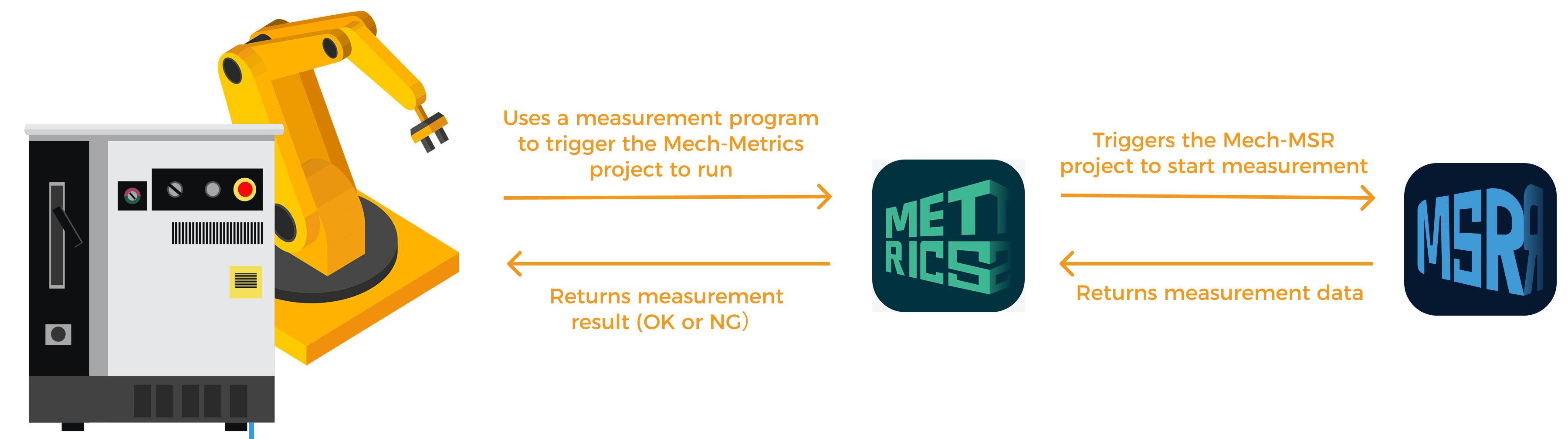
During the communication between the robot and Mech-Metrics, the robot establishes a connection with Mech-MSR, and Mech-MSR establishes a connection with Mech-Metrics. Once these connections are established, the specific communication method is shown as follows:
Measurement Data Analysis
- Measurement Record
-
Measurement records refer to the measurement records stored in the historical data of the software.
- Pareto Chart
-
A Pareto chart is a statistical analysis chart that combines bar and line charts to show the importance of various problems or factors to the overall impact. The bars, arranged in ascending order, represent the frequencies or values of each class. The line graph shows the cumulative percentage. A Pareto chart is commonly used to identify and prioritize the most significant problems (“the 80/20 rule”), helping users focus on the few key factors that have the greatest impact.
- Trend Charts
-
The trend chart displays the trend of the measurement data of each measurement feature along with the number of measurements in the form of a line chart, which helps you visualize the fluctuation and trend of the measured values.
- SPC
-
SPC stands for Statistical Process Control, which refers to the use of statistical methods to monitor each stage of the production process in order to ensure and improve product quality.
- USL
-
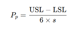
The Upper Specification Limit, abbreviated as USL, is the upper limit of a dimension, which is the nominal value plus the upper tolerance. For example, if the nominal length of a feature is 5mm and the tolerance is -1 to 1mm, the USL would be 6mm.
- LSL
-
The Lower Specification Limit, abbreviated as LSL, is the lower limit of a dimension, which is the nominal value plus the lower tolerance. For example, if the nominal length of a feature is 5mm and the tolerance is -1 to 1mm, the LSL would be 4mm.
- 3σ Rule
-
σ represents the standard deviation. The 3σ rule, also known as the three-sigma rule, is a method used in statistics to exclude outliers. It assumes that the data follows a normal distribution, and any data point that exceeds the mean plus or minus three standard deviations is considered an outlier and should be removed from the dataset. The 3σ control limits are used to check whether data points lie within three standard deviations of the mean.
- CL
-
The Central Line, abbreviated as CL, is a line consisting of the average values (
 ).
). - UCL
-
The Upper Control Limit, abbreviated as UCL, is the value obtained by adding 3σ to the average value.
- LCL
-
The Lower Control Limit, abbreviated as LCL, is the value obtained by subtracting 3σ from the average value.
- Control Chart
-
A control chart, is used to analyze and determine whether a process is in a state of control. It includes control limits. The control chart is based on the 3σ rule in normal distribution, where the central line represents the average value (
), and the upper and lower control limits are calculated by adding and subtracting 3σ from the average value. These limits are used to identify if there are any issues occurring in the process.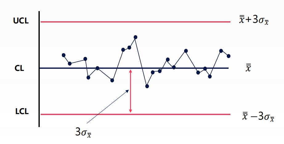
- Pp
-
The Process Performance (Pp) is used to assess whether the performance of a process meets specification requirements. The formula for calculating Pp is as follows. In this example, s represents the standard deviation of the sample.
- Ppk
-
The central performance index (“Process Performance Index” or Ppk) is used to evaluate whether the performance of a process meets specifications. Compared with Pp, Ppk takes into account the influence of the average process performance. The formula for calculating Ppk is as follows. In the above example,
represents the average value of the sample, and s represents the standard deviation of the sample.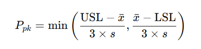
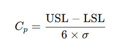
- Cp
-
The Process Capability (Cp) is used to evaluate whether the capabilities of a process meet the requirements. The formula for calculating Cp is as follows. In this example, σ represents the overall standard deviation.
- Cpk
-
The Process Capability Index (Cpk) is used to evaluate whether the capabilities of a process meet specifications. Compared with Cp, Cpk takes into account the influence of the average process capability. The formula for calculating Cpk is as follows. In the above example,
represents the overall average, and σ represents the overall standard deviation.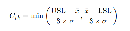
- Measurement Report
-
Measurement report is the official document that summarizes, analyzes, and displays the measurement results of parts. Reports usually contain information about measurement objects, measurement items, measurement data, deviation analysis, tolerance judgment, and statistical analysis. Mech-Metrics supports custom PDF-format and table-format measurement reports to meet different archiving, sharing, and data processing requirements. Measurement reports are widely used in quality traceability, process control, and delivery scenarios.
Software License
- Sentinel LDK
-
Sentinel License Development Kit (LDK) is a comprehensive software development toolkit that helps you efficiently manage software licenses and usage rights.
- Software Licensing Device
-
Software licensing device is a USB-based licensing method that supports writing licenses for different software by using a product key. This device is similar to the dongle used in previous software versions.
- Software Licensing Code
-
Software licensing code is a virtual licensing method that supports writing licenses for different software by using a product key.
- Permanent License
-
Permanent license is a license that allows for permanent use.
- Temporary License
-
Temporary license is a license that allows for temporary use. To extend the validity period of the license, update the license.
- Product Key
-
Product key is a unique code used to activate a license and unlock all or part of its features.
- Activate the License
-
License activation refers to authorizing a new software license on an unauthorized IPC using a product key.
- Update the License
-
License update refers to updating the software license to extend its validity period or change the software in use.
- Fingerprint File
-
Fingerprint file is a file that is used to generate the V2C or V2CP file. This file contains information about the IPC.
- C2V
-
Stands for customer to vendor. C2V file is a file that is used to generate the V2C or V2CP file. This file contains information about the software license device.
- V2C
-
Stands for vendor to customer. V2C file refers to the file used to update the license offline. This file contains information about the user’s license.
- V2CP
-
Stands for vendor to customer package. A V2CP file refers to a V2C file package that contains multiple V2C files.
Abbreviations
This section summarizes the abbreviations used in the manual for reference. For detailed explanations of the abbreviations, see the Terms and Concepts section of this document.
- CAD
-
Computer-Aided Design
- CL
-
Central Line
- CMM
-
Coordinate Measuring Machine
- Cp
-
Process Capability
- Cpk
-
Process Capability Index
- C2V
-
Customer to Vendor
- EIH
-
Eye in Hand
- ETH
-
Eye to Hand
- GD&T
-
Geometric Dimensioning and Tolerancing
- IPC
-
Industrial PC
- LCL
-
Lower Control Limit
- LSL
-
Lower Specification Limit
- PC
-
Personal Computer
- PLC
-
Programmable Logic Controller
- Pp
-
Process Performance
- ROI
-
Region of Interest
- Ppk
-
Process Performance Index
- RPS
-
Reference Point System
- SPC
-
Statistical Process Control
- UCL
-
Upper Control Limit
- USL
-
Upper Specification Limit
- V2C
-
Vendor to Customer
- V2CP
-
Vendor to Customer Package
- LDK
-
License Development Kit