Perform Thermal Drift Compensation Analysis
This section introduces how to perform thermal drift compensation analysis to check the effect of thermal drift compensation.
|
Before using the thermal drift compensation analysis function, please complete the following configurations:
-
When configuring part properties in Mech-Metrics, set the part class to thermal drift rod.
-
Create features for the drift rod, and assign corresponding Mech-MSR projects and parameter recipes to each feature.
-
Use the thermal drift compensation tool in Mech-MSR to associate the robot with the project and select whether to enable thermal drift compensation for each project.
To use the thermal drift compensation analysis function, follow these steps:
-
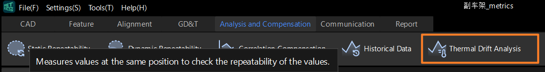
In the Mech-Metrics Configuration interface, go to the Analysis and Compensation tab and click Thermal Drift Analysis.
-
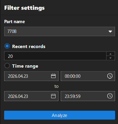
In the Filter settings area on the left, set the following filtering conditions according to your needs:
-
Part name: Select the drift rod to analyze from the drop-down list.
-
Recent records/Time range: Select the filter for the data. Select Recent records to filter by the number of recent measurement records; select Time range to set the start and end date and time to filter data within the specified time range.
-
-
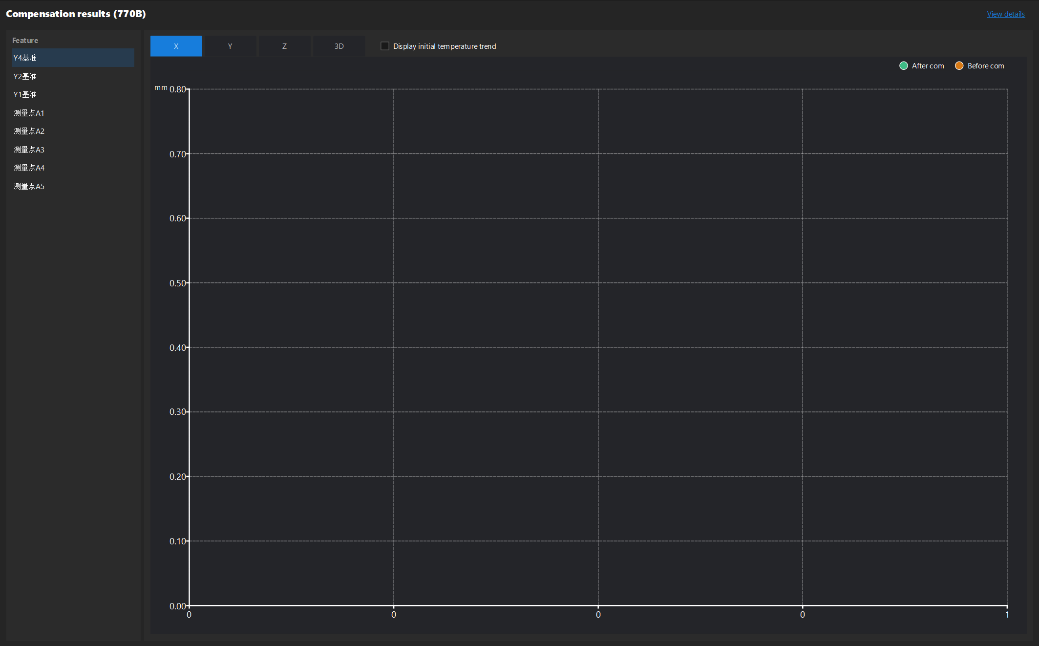
Click Analyze. A chart of thermal drift compensation results will be displayed on the right.
-
Click the X, Y, Z or 3D tabs to view the difference before and after compensation in each direction or combination.
-
The green dots in the chart represent the After compensation difference, while the yellow dots represent the Before compensation difference.
-
-
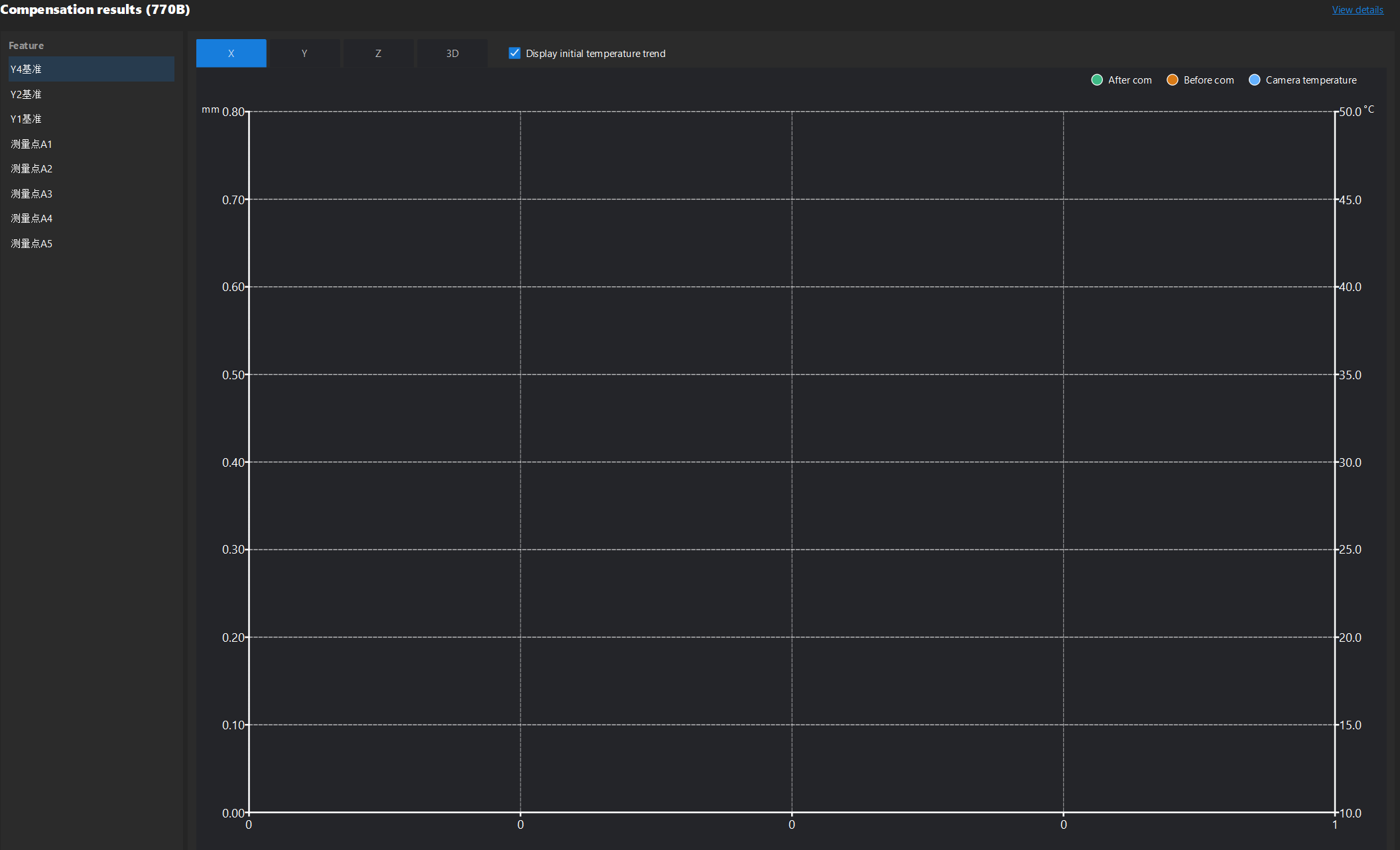
(Optional) Select the Display initial temperature trend checkbox in the upper right corner of the chart, and an additional camera temperature curve will be displayed in the chart.
-
The blue dots on the chart represent the Camera temperature, and the unit of temperature (°C) is displayed to the right of the vertical axis.
-