Pre-Deployment Checks
This section describes the pre-deployment checks that must be completed before entering project configuration and joint debugging.
The focus of this phase is to identify on-site risks in hardware, robots, tooling, electrical systems, and environment in advance, reducing the probability of rework in later stages.
Phase Goal
After this phase is completed, you should be able to confirm that on-site baseline conditions meet requirements for project configuration and joint debugging, and clearly identify issues that must be rectified first.
Entry Criteria
Before starting pre-deployment checks, it is recommended that the following conditions have been met:
-
Basic hardware installation and network connection are completed.
-
The camera can be connected normally and supports basic image acquisition.
-
The site has robots, tooling, and supporting electrical conditions in place.
Checklist Items
Before deploying an inline measurement solution, check required items one by one according to the table below.
| Category | Check Item | Required | Description | |
|---|---|---|---|---|
Camera-related checks |
Installation |
Yes |
|
|
Yes |
Connect the UHP-140-GL camera used in the project in Mech-Eye Viewer, then set Capture Mode to Camera1 on the Parameters tab on the right. Camera1 should be installed on the far side of the flange to ensure measurement performance, as shown below: 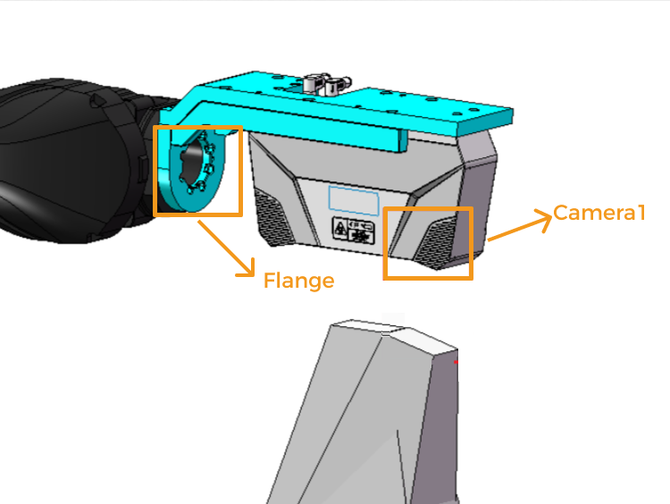
|
|||
Connection |
Yes |
|
||
Intrinsic parameters |
Yes |
Use the intrinsic parameter tool in Mech-Eye Viewer to verify that intrinsic parameters (for example, focal length and distortion) meet project accuracy requirements. |
||
Distance between camera and robot |
Yes |
Check whether the spacing between the camera housing and robot flange is too small, to avoid interference when adjusting robot trajectories. |
||
Ambient light |
Yes |
Confirm whether on-site ambient light affects imaging quality. |
||
Robot-related checks |
Installation |
Yes |
Check whether the robot is firmly installed, including:
|
|
Zero point and repeat accuracy |
Yes |
Perform robot zero-point verification and check robot repeat accuracy. |
||
Communication software packages |
Yes |
Check whether robot communication software packages are installed, including:
|
||
Layout validation |
Yes |
Perform robot layout and reachability checks, including:
|
||
Tooling-related checks |
CAD model |
Yes |
Confirm that on-site tooling is consistent with the CAD model. |
|
Installation |
Yes |
Check whether tooling is firmly installed, including:
|
||
Locating pin extension/retraction |
Yes |
Check whether locating pins extend/retract smoothly with no sticking or blockage. |
||
Locating pin hardness |
Yes |
Confirm tooling locating pins have passed hardness testing and corresponding hardness reports are available. |
||
Accuracy |
Yes |
If a tooling reference frame is required, confirm a CMM report is available and tooling accuracy meets requirements. |
||
Whether clamp head blocks measurement hole |
Yes |
Check whether tooling clamp heads block measurement holes. Ensure more than half of each measurement hole remains unblocked. |
||
Cylinder pressure regulator |
Yes |
Confirm each cylinder on tooling is equipped with an independent pressure regulator. |
||
Whether all clamp heads can clamp effectively |
Yes |
Confirm clamp heads for multiple parts can clamp effectively, and proximity sensors can stably detect clamped status. |
||
Mechanical checks |
Part CAD model confirmation |
Yes |
Tooling is manufactured based on the latest part CAD version. |
|
Datum design style |
Yes |
Confirm datum structures conform to design style, datum positions meet vision inspection requirements, and no interference with equipment occurs during inspection. |
||
Coating color |
Yes |
Ensure color codes meet end-user requirements and technical agreement requirements. |
||
Markings |
Yes |
Ensure all markings on tooling do not interfere with the actual inspection process. |
||
Nameplate values |
Yes |
Ensure datum coordinate values on physical tooling nameplates are consistent with the inspection accuracy table. |
||
Overall appearance |
Yes |
|
||
Rust prevention / golden paint |
Yes |
Ensure all tooling parts are rust-proofed as required, and golden paint surfaces are clear, uniform, and aesthetically acceptable. |
||
Clamp head and clamping force |
Yes |
Ensure clamp heads properly contact part surfaces with suitable clamping force when material thickness is considered. |
||
Brand list check |
Yes |
Ensure all mechanical component brands have been checked and comply with technical agreement requirements. |
||
Cylinder opening angle |
Yes |
Ensure no mutual interference among movable parts, and cylinder opening angles meet requirements. |
||
Electrical checks |
Electrical cabinet and cable trunking |
Yes |
Ensure fixture electrical cabinet cables are neatly arranged, cable trunking covers are installed, and anti-cut strips are installed at metal trunking openings. |
|
Yes |
Ensure waterproof cable glands are installed at cable pass-throughs and no cable conductors are exposed. |
|||
Fixture wiring |
Yes |
Ensure all push buttons, sensor cables, and components are labeled. |
||
Yes |
Ensure cylinder open/close signals are consistent with drawings and nameplates. |
|||
Yes |
Ensure wiring of rotary/moving mechanisms has cable clamps at upper ends to secure moving positions. |
|||
Yes |
Ensure anti-spatter and high-temperature protection measures are applied to cables and sensor cables (silicone tube/glass fiber tube). |
|||
Yes |
Ensure fixture wiring is tested using external 24 V power after completion. |
|||
Yes |
Ensure magnetic switches of all cylinders are powered on and adjusted to clamped/open positions with clear markings. |
|||
Other checks |
Vibration sources |
Yes |
Confirm whether there are obvious vibration sources on site (for example, punching machines and presses). |
|
Part qualification status |
Yes |
Confirm whether parts used during tooling debugging are qualified parts. |
||
Locating pin spare parts |
Yes |
Confirm whether spare locating pins are available on site. |
||
Nominal values of reference balls |
Yes |
Confirm whether nominal values of tooling reference balls are consistent with nominal values in the tooling CMM report. |
||
Welding light sources |
Yes |
Confirm whether welding light sources or strong direct light affect imaging quality on site. |
Completion Criteria
After this phase is completed, the following conditions should be met:
-
All required checklist items in the table are confirmed, or clear rectification conclusions are documented.
-
No blocking issues remain that affect safety, image quality, reachability, or communication stability.
-
The site is ready to enter the Project Configuration and Deployment phase.