Configure Control Items for the Feature
After creating a feature, you need to configure control items for the feature. Control items are used to control the features and control their quality. This section introduces how to create and configure control items.
|
The software defines the following three types of control items:
-
Dimensional control item: The dimensional properties of a feature, such as X, Y, Z, and Radius.
-
Geometric tolerance control item: Geometric tolerances based on GD&T standards, such as positional tolerance and flatness.
-
Custom control item: Custom control items, such as external data such as temperature and humidity.
The system consistently uses the following judgment logic to determine the qualification of all control items: Deviation = Measured value - Nominal value. If the deviation is within the tolerance range, it is judged as acceptable; otherwise, it is judged as unacceptable.
In the Control item settings area of the right parameter panel, you can perform the following actions:
Configure Dimension Control Items
Dimension control items refer to the dimensional attributes (such as X, Y, Z, radius, etc.) of a feature. After creating a feature, you can select the dimensional control items to be enabled as needed.
|
Please follow these steps to configure the dimension control items:
-
In the resource tree section on the left, select a feature.
-
In the Control Item Settings section on the right-side parameter panel, click the Edit Dimension Control Item button
 .
. -
In the pop-up Dimension control items dialog box, select the desired dimension control items, and then click OK.
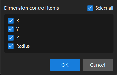
You can select Select all to quickly select all dimension control items.
Edit Tolerance Band
Set a tolerance band for the control item, which is used to determine whether the measured value is within the allowable range. The upper and lower limits of the tolerance band are the deviation values relative to the nominal values. For example, if the nominal value of a control item is 10, and the first tolerance band is set to -1.000 and 1.000, the actual allowable range is 9.000 to 11.000.
The software supports setting three tolerance bands for each control item.
Follow these steps to edit the tolerance band:
-
In the resource tree section on the left, select a feature. In the top-right corner of the Control Item Settings section on the right-side parameter panel, click the Edit Tolerance Band button
 .
. -
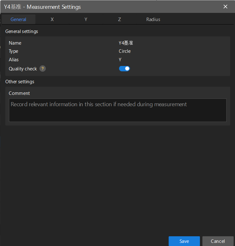
In the pop-up Measurement Settings dialog box, select the General tab to view and configure the following general settings:
-
Name: The name of the current feature.
-
Compensation type: The type of the current feature.
-
Alias: The alias of the current feature.
-
Quality check: If this feature is disabled, the measurement item will not participate in the qualification judgment, and its annotation cards will be hidden in the 3D view.
-
Comment: Relevant information in the measurement process can be recorded here.
-
-
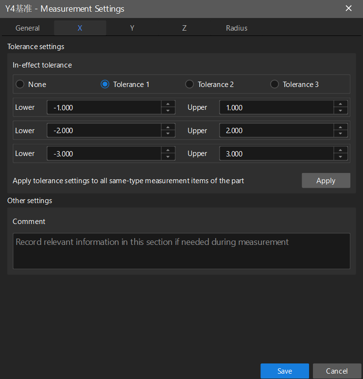
Click the Control Items tab (such as X) to set the tolerance band for the control item:
-
Set the In-effect tolerance: select None, Tolerance 1, Tolerance 2, or Tolerance 3.
-
Set the Lower and Upper of the tolerance bands for each level:
-
Tolerance 1: Set the lower limit and upper limit, such as -1.000 to 1.000.
-
Tolerance 2: Set the lower limit and upper limit, such as -2.000 to 2.000.
-
Tolerance 3: Set the lower limit and upper limit, such as -3.000 to 3.000.
The above values are only used as reference examples. Please set the Actual Tolerance Band parameter according to the specifications of the part.
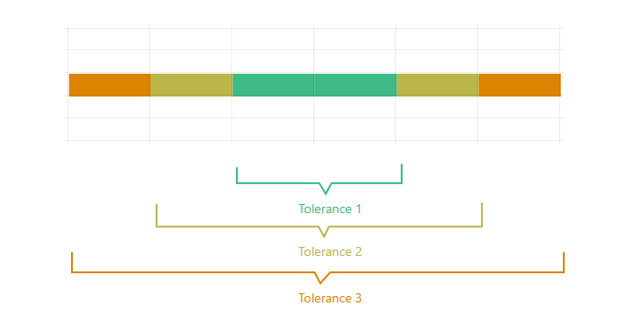
The following figure shows the legend of the three-level tolerance band, which is helpful for understanding. The green one represents Tolerance 1, the yellow one represents Tolerance 2, and the orange one represents Tolerance 3.
-
-
If you want to apply the tolerance settings to all same-type measurement items of the current part, click Apply.
-
-
Set tolerance bands for other control items (such as Y, Z, Radius, etc.) as needed, and then click Save.
This method is also applicable to setting tolerance bands for geometric tolerance control items and custom control items.
Create a Geometric Tolerance Control Item
|
You can create the following seven geometric tolerance control items:
You can create geometric tolerance control items in two ways:
-
Through the Geometric Tolerances tab at the top: Select a feature, click the Geometric Tolerances tab, and then select the type of geometric tolerance you want to create.
-
Through the parameter panel on the right: Select a feature, in the Control item settings area, click the Create geometric tolerance button
 , and then select the type of geometric tolerance you need.
After creating geometric tolerance control items, you can edit the tolerance bands for them. For details, refer to Edit Tolerance Band.
When creating geometric tolerances, you need to specify the geometric tolerance name and configure the feature control frame in the GD&T Settings dialog box.
If the Mech-MSR measurement project outputs a single GD&T, the communication key of a single GD&T can be set to "gdt". If the measurement project outputs multiple GD&Ts, the communication key of each GD&T should be set to the name set here. In other words, the communication key must be consistent with the GD&T names configured in Mech-Metrics to ensure that Mech-Metrics can correctly distinguish between different GD&T data.
The following explains the meanings of each element of the feature control frame:
|
Feature control frames are used to label geometric tolerances. Taking the following feature control frame as an example, each segment is labeled with the following information from left to right: 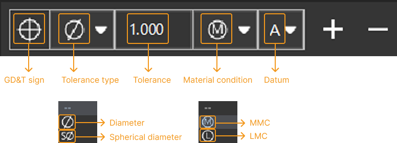
|
Create Flatness
Follow these steps to create a flatness:
-
In the Mech-Metrics configuration interface, click the Geometric Tolerances tab, and then click Flatness.
-
In the GD&T Settings dialog box, set the following information:

-
Name.
-
Configure the elements in the feature control frame according to the actual situation.
-
Set the Measurement method.
-
-
Click OK.
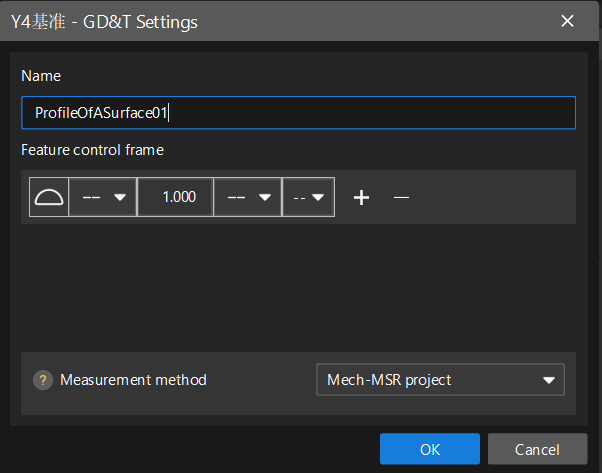
Create Surface Profile
Follow these steps to create a surface profile:
-
In the Mech-Metrics configuration interface, click the Geometric Tolerances tab, and then click Surface Profile.
-
In the GD&T Settings dialog box, set the following information:
-
Specify the Name.
-
Configure the elements in the feature control frame according to the actual situation.
-
Set the Measurement method.
-
-
Click OK.
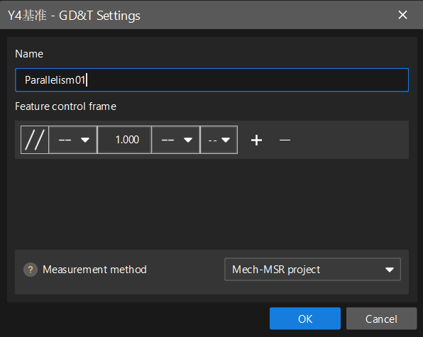
Create Parallelism
Follow these steps to create a parallelism:
-
In the Mech-Metrics configuration interface, click the Geometric Tolerances tab, and then click Parallelism.
-
In the GD&T Settings dialog box, set the following information:
-
Specify the Name.
-
Configure the elements in the feature control frame according to the actual situation.
-
Set the Measurement method.
-
-
Click OK.
Create Perpendicularity
Follow these steps to create a perpendicularity:
-
In the Mech-Metrics configuration interface, click the Geometric Tolerances tab, and then click Perpendicularity.
-
In the GD&T Settings dialog box, set the following information:

-
Specify the Name.
-
Configure the elements in the feature control frame according to the actual situation.
-
Set the Measurement method.
-
-
Click OK.
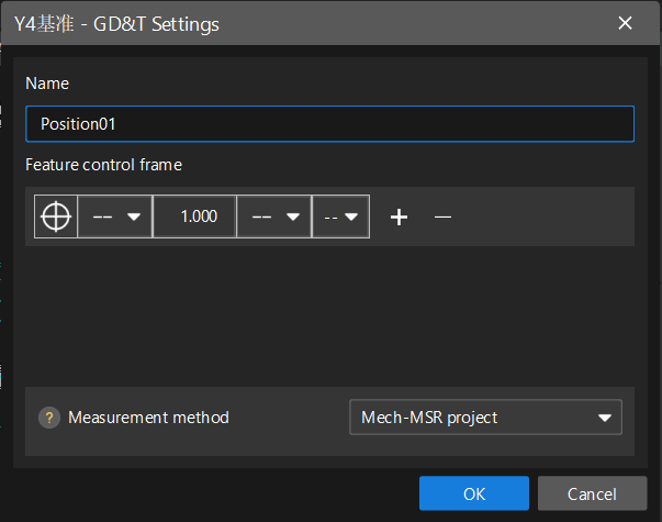
Create Position
Please follow these steps to create a position:
-
In the Mech-Metrics configuration interface, click the Geometric Tolerances tab, and then click Position.
-
In the GD&T Settings dialog box, set the following information:
-
Specify the Name.
-
Configure the elements in the feature control frame according to the actual situation.
-
Set the Measurement method.
-
-
Click OK.
Create Concentricity
Follow these steps to create a concentricity:
-
In the Mech-Metrics configuration interface, click the Geometric Tolerances tab, and then click Concentricity.
-
In the GD&T Settings dialog box, set the following information:

-
Specify the Name.
-
Configure the elements in the feature control frame according to the actual situation.
-
Set the Measurement method.
-
-
Click OK.
Create Symmetry
Follow these steps to create a symmetry:
-
In the Mech-Metrics configuration interface, click the Geometric Tolerances tab, and then click Symmetry.
-
In the GD&T Settings dialog box, set the following information:
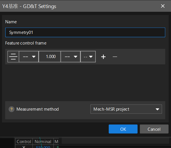
-
Specify the Name.
-
Configure the elements in the feature control frame according to the actual situation.
-
Set the Measurement method.
-
-
Click OK.
Create Custom Control Items
The custom control item is used to obtain custom data from a Mech-MSR project or data from an external device. If you cannot find any control items that meet your needs in the software (such as inputting ambient temperature for unified management of measurement data), you can create custom control items.
Follow these steps to create a custom control item:
-
Click a feature in the resource tree on the left. In the Control Item Settings section of the parameter panel on the right, click the Create custom control item button
 .
. -
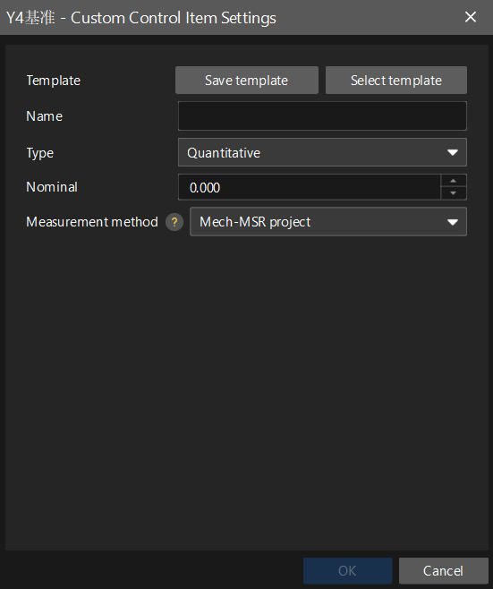
In the Custom Control Item Settings dialog box, set the following information:
-
Template: You can click Save Template to save the template that you set as a template, or click Select Template to use the saved template.
-
Name: Enter the name of the custom control item. For custom control items of features, the communication key must match the names of the custom control items configured in Mech-Metrics.
-
Type: The type is Quantitative by default (not adjustable).
After saving the template, you can reuse it for other features. Click the Create custom control item button
. In the Custom Control Item Settings dialog box, click Select template and select the saved template from the drop-down list.
-