Thermal Drift Compensation Solution
This section introduces thermal drift in inline measurement scenarios, along with the composition, working principle, and deployment method of the inline measurement thermal drift compensation solution.
What Is Thermal Drift?
In inline measurement scenarios, thermal drift refers to the slow offset of measurement results caused by temperature changes in equipment. Thermal drift usually has the characteristics of "small magnitude, continuous accumulation, and variation with environment and equipment state". It may not be obvious in a single measurement, but after long-term operation it appears as trend drift in results.
For the inline measurement system, thermal drift is mainly reflected in the following aspects:
-
Temperature changes of robots, cameras, tooling, and the on-site environment cause offsets in point cloud and feature fitting results.
-
The distribution center of the same feature shifts across different time periods, and repeatability indicators deteriorate.
-
Quality fluctuation appears on site as "normal in early stage, gradually deviating in later stage".
Overview of the Thermal Drift Compensation Solution for Inline Measurement Systems
When the production line enters mass-production operation, thermal drift directly affects decision quality in mass production. The goal of thermal drift compensation is not to replace process capability, but to compensate temperature-related offsets in the existing measurement chain and maintain long-term result stability.
This solution mainly addresses the following issues:
-
Measurement mean values drift slowly after long-cycle operation, increasing false-judgment risk.
-
Result consistency decreases across day/night shifts, seasonal changes, or workshop temperature-control fluctuations.
-
Production cycle time is stable but measurement results drift, making troubleshooting costly and difficult.
Composition and Working Principle of the Thermal Drift Compensation Solution
Solution Composition
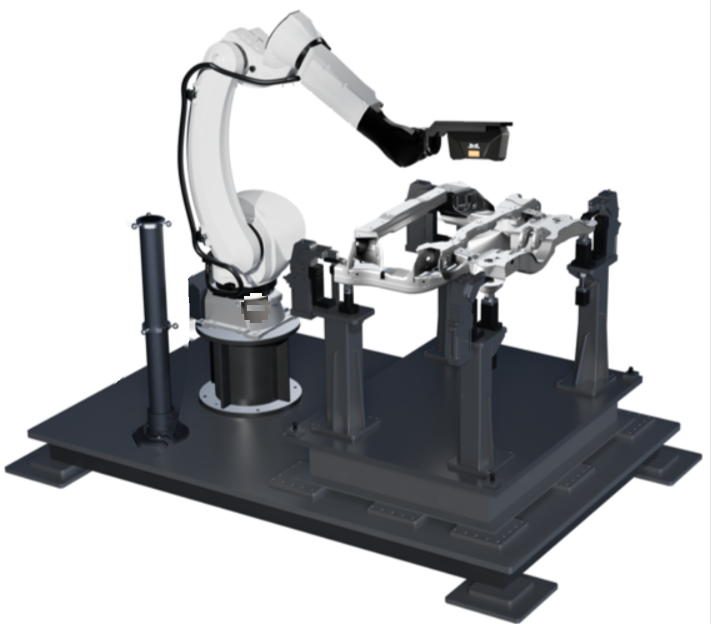
The thermal drift compensation solution consists of four parts: thermal drift rod, robot side, Mech-Metrics, and Mech-MSR.
| Component | Positioning | Core Responsibility |
|---|---|---|
Thermal drift rod |
Stable reference body |
Acts as a fixed geometric reference object in long-term operation and continuously provides drift sample data under changing temperature conditions. |
Robot side |
Process orchestration and cycle driving |
PLC triggers thermal drift rod calibration sphere measurement at predefined timing, while the robot program executes robot motion and image acquisition. |
Mech-Metrics |
Data receiving and compensation effect analysis |
Manages thermal drift rod part and feature configuration, receives data before/after compensation, and provides thermal drift analysis and trend comparison capabilities. |
Mech-MSR |
Measurement execution and compensation calculation |
Executes thermal drift rod measurement projects, completes robot-project association, and outputs compensated measurement results. |
Working Principle
The operation mechanism of thermal drift compensation can be summarized as a closed loop of "sampling, modeling, compensation, and verification":
-
The robot program triggers thermal drift rod measurement at predefined timing (usually by PLC or upper computer signal), and the system continuously acquires reference samples under different temperature conditions.
-
Mech-MSR executes thermal drift rod measurement projects and applies compensation strategy to output compensated data.
-
Mech-Metrics receives pre-/post-compensation results and compares them in the same analysis view.
-
Through linked trend analysis of X/Y/Z/3D and temperature, determine whether compensated data converges and whether long-term one-way drift is suppressed.
In engineering practice, thermal drift compensation focuses on "all-time trend stability" rather than occasional improvement at a single point.
Deploy the Thermal Drift Compensation Solution
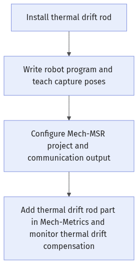
It is recommended to implement according to the following process to ensure the thermal drift compensation chain is fully connected:
-
Install the thermal drift rod.
-
Write the robot program and teach capture poses.
-
Configure Mech-MSR projects and communication output.
-
Add a thermal drift rod part in Mech-Metrics and monitor thermal drift compensation.
Install the Thermal Drift Rod
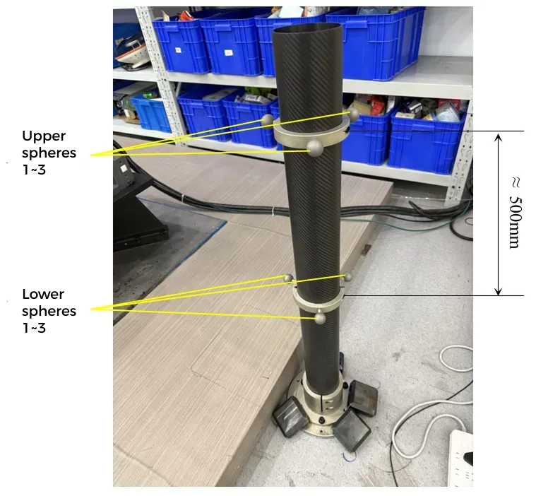
Deployment of the thermal drift compensation solution requires the standard "calibration rod" product provided by Mech-Mind (hereinafter referred to as the "thermal drift rod"). The product includes a rod assembly with six calibration spheres, together with related accessories and installation tools.
Before installing the thermal drift rod, first ensure the following mandatory requirements are met:
-
Install the thermal drift rod on one side of the robot, and ensure the robot can reach capture poses for all six calibration spheres.
-
When adjusting upper and lower ball-ring positions, keep the upper ring higher than the part and the lower ring lower than the part, with a height difference between 450 and 550 mm.
After the above conditions are satisfied, complete installation with the following steps:
-
Install and mechanically fix the thermal drift rod on site, ensuring no looseness or displacement risk.
-
Recheck that capture poses for all six calibration spheres are reachable; fine-tune rod position if necessary.
-
Adjust upper/lower ball-ring heights and recheck height difference to ensure it remains stably within 450-550 mm.
-
Perform multiple dry runs to confirm no collision risk among robot, camera, and thermal drift rod.
Write the Robot Program and Teach Capture Poses
Write the Robot Program
The following is a FANUC robot sample program. For other robot brands, write programs by following the same logic.
1: !-------------------------------- ;
2: !FUNCTION: MSR_Metrics_Sample1 ;
3: !Mech-Mind, 2025-12-24 ;
4: !-------------------------------- ;
5:
6: !set current uframe NO. to 0 ;
7: UFRAME_NUM=0 ;
8: !set current tool NO. to 1 ;
9: UTOOL_NUM=1 ;
10: ;
11: LBL[1] ;
12: !Init Socket!Modify IP Address ;
13: CALL MSR_INIT_SKT('8','192.168.1.20',50000,5) ;
14: !Set Custom Values ;
15: CALL MSR_MEAS_PARM(0,0,0,0,0,0,0,0) ;
16: !SR:String Register; R:Register ;
17: !Set Robot_Id,SR No.1,SR No.2,Qc_Mode,R NO.1,R NO.2;
18: !SR No.1:Piece_Name ;
19: !SR No.2:Piece_Sn ;
20: !R No.1:Continuous Mode, R No.2:MM Status ;
21: CALL MSR_ST_MEAS(1,11,12,0,10,95) ;
22: ;
23: !move to robot home position ;
24:J P[0] 100% FINE ;
25: ;
26: !UP-BALL1 ;
27:J P[1] 100% FINE ;
28: WAIT 1.00(sec) ;
29: CALL MSR_MEAS_FEAT(1,101,95) ;
30:J P[2] 100% FINE ;
31: WAIT 1.00(sec) ;
32: CALL MSR_MEAS_FEAT(1,102,95) ;
33:J P[3] 100% FINE ;
34: WAIT 1.00(sec) ;
35: CALL MSR_MEAS_FEAT(1,103,95) ;
36:J P[4] 100% FINE ;
37: WAIT 1.00(sec) ;
38: CALL MSR_MEAS_FEAT(1,104,95) ;
39: ;
40: !UP-BALL2 ;
…
130: ;
131: WAIT .50(sec) ;
132: CALL MSR_END_MEAS(1,10,91,92,93,95) ;
133: ;
134: !Init Socket!Modify IP Address ;
135: CALL MSR_INIT_SKT('8','192.168.1.20',50000,5) ;
136: !Set Custom Values ;
137: CALL MSR_MEAS_PARM(0,0,0,0,0,0,0,0) ;
138: !SR:String Register; R:Register ;
139: !Set Robot_Id,SR No.1,SR No.2,Qc_Mode,R NO.1,R NO.2;
140: !SR No.1:Piece_Name ;
141: !SR No.2:Piece_Sn ;
142: !R No.:Continuous Mode, R No.2:MM Status ;
143: CALL MSR_ST_MEAS(1,5,6,0,10,95) ;
144: ;
145: !Feature1 ;
146:J P[41] 100% FINE ;
147: WAIT 1.00(sec) ;
148: CALL MSR_MEAS_FEAT(1,101,95) ;
149: !Feature2 ;
…
234: ;
235: WAIT .50(sec) ;
236: CALL MSR_END_MEAS(1,10,91,92,93,95) ;
237: ;
238: WAIT .50(sec) ;
239:J P[71] 100% FINE ;
240: JMP LBL[1] ;
241: PAUSE ;The table below explains the program logic.
| Line range | Logic description |
|---|---|
1–10 |
Basic settings. |
11 |
Jump label (for loop execution). |
12–22 |
Robot communication settings and start measurement task (corresponding to the thermal drift rod part in Mech-Metrics).
|
23–25 |
Move to robot Home position. |
26–39 |
Capture data of calibration sphere 1.
|
40–130 |
Capture data of calibration spheres 2 to 6. |
131–133 |
End measurement task. |
134–144 |
Robot communication settings and start measurement task (corresponding to production parts in Mech-Metrics). |
145–234 |
Capture target features of production parts. |
235–237 |
End measurement task. |
238–239 |
Move robot to transition point. |
240 |
Jump label. Used with line 11 to implement loop execution of the robot program. |
Teach Capture Poses
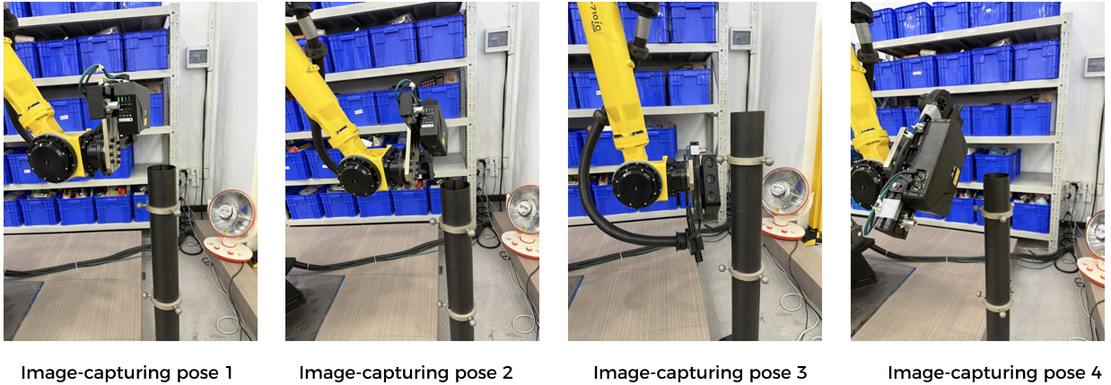
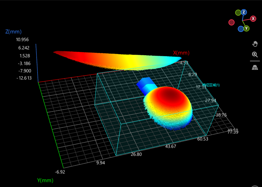
Teach calibration sphere capture points so that the robot captures each calibration sphere with four different poses. There are six calibration spheres on the upper and lower sections of the thermal drift rod, for a total of 24 capture points.
The four capture poses of each calibration sphere should have clear differences to ensure diversity of sampling directions. They do not need to be exactly the same as angles or poses shown below.
Configure Mech-MSR Projects and Communication Output
On the Mech-MSR side, complete the following tasks:
-
Configure the thermal drift rod calibration sphere project: ensure stable recognition of key features, and verify measurement items and communication keys in Output Management so they correspond one-to-one with the Mech-Metrics side.
-
Enable thermal drift compensation for measurement projects: use the thermal drift compensation tool to associate robots and projects, and enable compensation per project.
-
Configure communication output: ensure compensated measurement results are correctly sent to Mech-Metrics via communication output, and communication keys are consistent with Mech-Metrics settings.
Configure Thermal Drift Rod Calibration Sphere Project
The "Subframe Demo Project" in the getting started tutorial contains the "Training Set 6 Balls" project, which is used to collect calibration sphere data of the thermal drift rod and update the thermal drift compensation model.
The structure of the "Training Set 6 Balls" project is as follows:
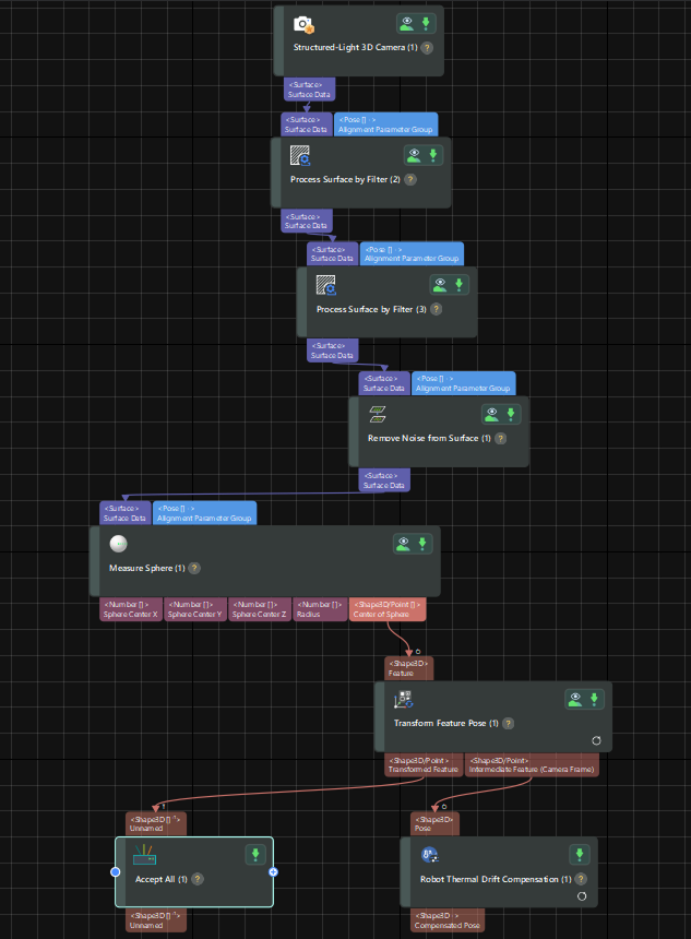
Key steps of this project are as follows:
-
Surface preprocessing:
Set a 3D ROI, confirm Filter Type is "Crop", and enable Use Feature Region.
There are six calibration spheres in total on the upper and lower sections of the thermal drift rod, and each ball is captured from four angles. You can use one larger ROI to cover the shared area for all 6 x 4 = 24 points.
-
Robot thermal drift compensation
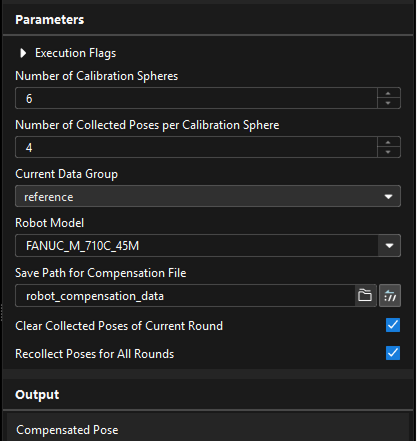
During deployment, configure thermal drift compensation parameters as shown below:
-
Current data group: includes "Baseline Group" and "Observation Group". For first run, set to "Baseline Group". After the first round completes, software automatically switches to "Observation Group".
-
Robot model: select the corresponding robot model.
-
Compensation file save path: default is folder "robot_compensation_data" under the project directory.
-
Clear poses collected in current round: checked by default. After run starts, software automatically switches it to unchecked.
-
Recollect poses in all rounds: checked by default. After run starts, software automatically switches it to unchecked.
In subsequent runs, if one full round of calibration sphere collection (24 points) is interrupted unexpectedly before completion, configure corresponding parameters as shown below and rerun the robot program.
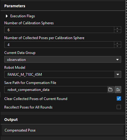
-
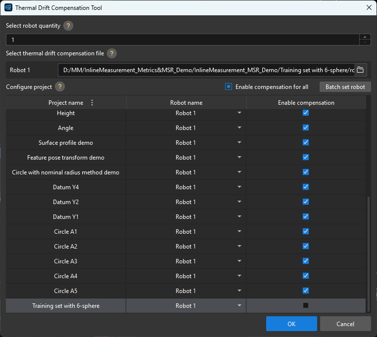
Enable Thermal Drift Compensation for Measurement Projects
-
In the Mech-MSR menu bar, open . The thermal drift compensation tool dialog opens.
-
Select robot quantity, choose compensation file path for each robot, configure robot-to-project mapping, and enable compensation.
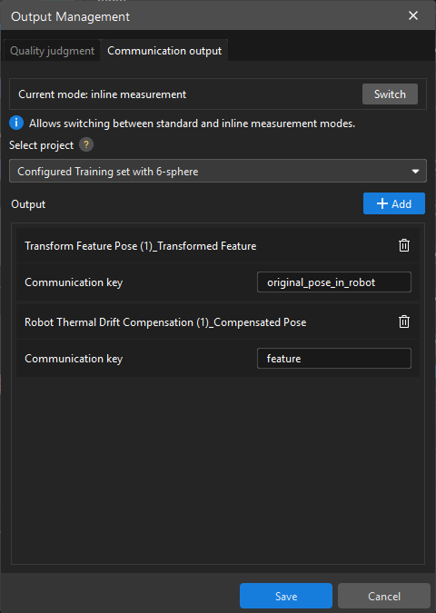
Configure Communication Output
Measurement data of Mech-MSR is sent to Mech-Metrics through the "communication key" in .
-
If a measurement project outputs only one feature, set communication key to "feature".
-
If a measurement project outputs one feature and one GD&T, set communication key of the feature to "feature" and communication key of GD&T to "gdt".
-
If a measurement project outputs multiple features and multiple GD&Ts, communication key of each feature must be set to the corresponding feature name in Mech-Metrics, and communication key of each GD&T must be set to the corresponding GD&T name in Mech-Metrics. In other words, communication keys must match naming configuration in Mech-Metrics. Only then can Mech-Metrics correctly distinguish data of different features and GD&Ts.
For calibration sphere projects, communication output keys are fixed as follows:
| Measurement item | Communication key |
|---|---|
Transformed feature output by Feature Pose Transformation step |
original_pose_in_robot |
Compensated pose output by Robot Thermal Drift Compensation step |
feature |
Add Thermal Drift Rod Part in Mech-Metrics and Monitor Thermal Drift Compensation
Import Thermal Drift Rod Part
The "Subframe Demo Project" in the getting started tutorial contains a thermal drift rod part (sphere.mtpart), which you can import into Mech-Metrics.
-
Open Mech-Metrics. In the menu bar, select .
-
In the dialog box, select sphere.mtpart in the subframe demo project, then click Open.
-
In the Import Part dialog box, click OK.
-
Select the part in the resource tree, then confirm in the property editor that Part category is set to Thermal Drift Rod, and modify the solution path to the actual Mech-MSR solution path.
Under the Feature node in the resource tree, you can see 24 features, corresponding to four capture poses for each of six calibration spheres.
Monitor Thermal Drift Compensation
-
In Mech-Metrics software configuration, under the Analysis and Compensation tab, click Thermal Drift Analysis.
-
In the filter area on the left, set filter conditions as needed, then view thermal drift compensation effects on the right.
Usually, it is sufficient to check compensation effects of the thermal drift rod part. For thermal drift rods, the tool shows two curves: "Thermal Drift Before Compensation" and "Thermal Drift After Compensation".
For production parts, only one curve is displayed: "Difference Before and After Compensation", that is, the compensation value.
- Why is the chart for production parts different from the thermal drift rod?
-
For production parts, each measurement on the production line is for a different part, so pre-/post-compensation values cannot be compared directly like a fixed thermal drift rod.
Different parts naturally have individual differences, so measured values inherently fluctuate.
If pre-/post-compensation absolute-value curves are still plotted, changes caused by part differences are mixed in, making compensation effects difficult to judge directly.