Tutorial: Subframe Inline Measurement
This tutorial is for users who are new to the inline measurement system and provides a fast learning path for getting started.
You will sequentially complete acquisition and recognition of the subframe demo project, local simulation verification, understanding of project structure and key measurement workflow, and a first minimal modification exercise.
Tutorial Scope and Learning Objectives
This tutorial focuses on "quick start" and does not expand parameter details or full deployment procedures.
- Estimated time
-
45-60 minutes.
- After completion, you will be able to
-
-
Download and identify key resources in the subframe demo project.
-
Complete local simulation and view measurement results.
-
Understand role division between Mech-MSR and Mech-Metrics in the subframe demo project.
-
Complete one minimal modification exercise based on the demo project.
-
Prerequisites and Preparation Checklist
Before you start, make sure the following conditions are met:
-
Mech-Metrics and Mech-MSR are installed and can be started normally. If not, refer to Installation Guide first.
-
You already have a basic understanding of the inline measurement solution composition.
For background information, read Inline Measurement Solution Overview first.
Obtain the Demo Project
Download and unzip the subframe demo project package:
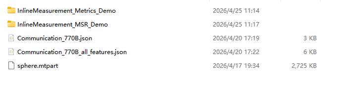
After extraction, you will get the following three categories of resources:
-
InlineMeasurement_Metrics_Demo: Mech-Metrics project.
-
InlineMeasurement_MSR_Demo: Mech-MSR solution. The solution folder contains all measurement projects.
-
Communication_770B.json, Communication_770B_all_features.json: communication simulator configuration files.
The two communication configuration files are for different scenarios:
-
Communication_770B.json: corresponds only to part "Subframe 770B", suitable for single-part verification and dynamic repeatability testing.
-
Communication_770B_all_features.json: can operate two parts at the same time, suitable for understanding full demo project structure.
Run Through the Demo in 5 Minutes
-
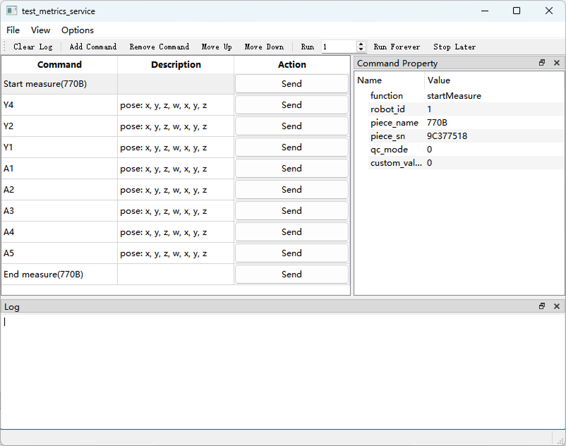
Open the Mech-Metrics/bin directory under the installation directory of Mech-Metrics and Mech-MSR, then run the communication simulator test_metrics_service.exe.
-
In the communication simulator, select and load a communication configuration file.
For first verification, it is recommended to load Communication_770B.json first. If you need to experience workflows for two parts at the same time, load Communication_770B_all_features.json.
-
Open the demo project in Mech-Metrics, confirm that the demo part list is displayed, and for first-time operation prioritize verification with the part corresponding to "Subframe 770B".
-
Open the demo solution in Mech-MSR, and confirm that measurement projects for all features are displayed in the project list.
-
In the communication simulator, send commands in full workflow order: send one start measurement command, then send multiple feature measurement commands in sequence (commands between start and end measurement), and finally send an end measurement command.
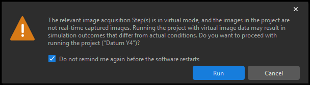
When feature measurement starts, Mech-MSR pops up a warning dialog asking whether to run the project with virtual image data. Select Do not remind again before software restart, then click Run.
-
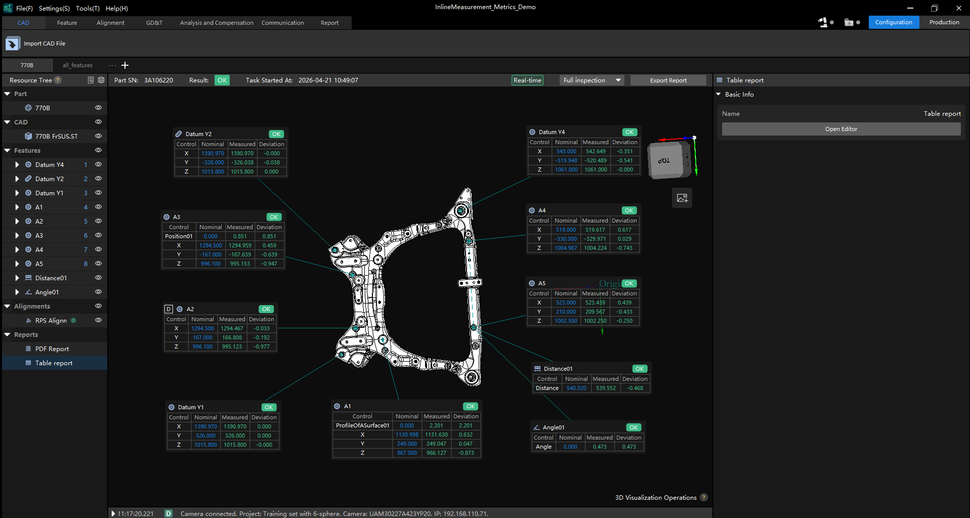
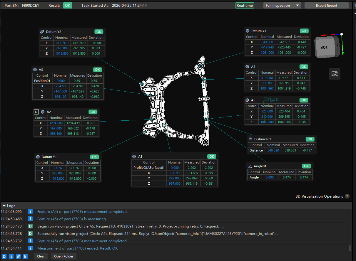
In the 3D view area of the Mech-Metrics demo project, confirm measurement results are updated; in the bottom log panel, confirm logs of the whole measurement process are available.
After completing this section, it is recommended to confirm at least the following:
-
Commands in the communication simulator can be sent normally, with no obvious errors.
-
Measurement results generated in this run can be viewed in Mech-Metrics, and complete process logs are visible in the log panel.
-
In continuous runs, the system can stably generate measurement results.
If any of the above is not achieved, first check command order, whether current part selection is correct, and whether the demo project is fully loaded.
Understand the Subframe Inline Measurement Solution
It is recommended to understand the solution from the following three aspects:
-
What to measure: dimensions and geometric quality of key subframe features.
-
How to measure: Mech-MSR performs image processing and feature extraction, while Mech-Metrics handles parts, features, IDs, judgment, and result management.
-
What to check: whether features are recognized correctly, whether results are output stably, and whether output fields are received correctly by Mech-Metrics.
Understand the Mech-Metrics Demo Project in 10 Minutes
In this demo project, prioritize understanding the following two parts in Mech-Metrics:
-
Subframe 770B: contains the full workflow of feature creation, alignment setup, measurement, and report generation. Suitable for understanding the complete process from alignment to result output for real parts.
-
Common Features all_features: centrally demonstrates common features such as reference balls, round holes, slot holes, square holes, threaded holes, studs/screws, face points, height, and angle, while covering typical scenarios including GD&T, custom controls, and multiple features sharing one measurement project.
After opening the Mech-Metrics demo project, these two parts appear above the resource tree. While reading this tutorial, first locate "Subframe 770B" in the part list and complete one workflow verification, then switch to "Common Features all_features" to review examples of different feature types.
In the resource tree, click the following nodes in sequence and understand corresponding content:
-
Part: learn how to create a part and configure part properties. Refer to Part Operation Guide.
-
CAD: view part CAD model and learn how to associate CAD files with a part. Refer to Import CAD Reference Objects for a Part.
-
Feature: view feature list under the part, learn definitions and property settings for different feature types, understand settings of various controls and annotation cards. Refer to Feature Operation Guide.
-
Alignment: understand relationships between reference frames, the current alignment method, and the features/parameters used in alignment. For reference frame details, refer to Reference Frames. For operation details, refer to Alignment Operation Guide.
-
Report: view current report format, try modifying format and exporting reports. Refer to Use Measurement Reports.
Understand the Mech-MSR Demo Project in 10 Minutes
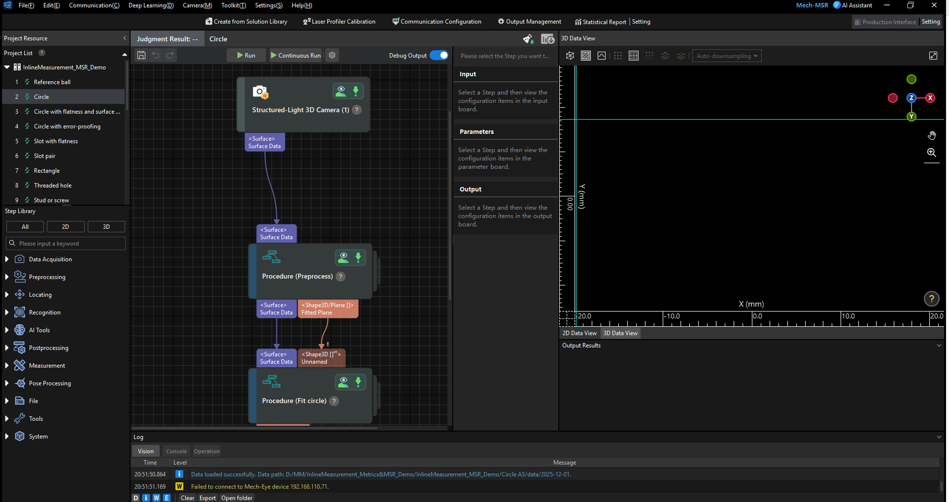
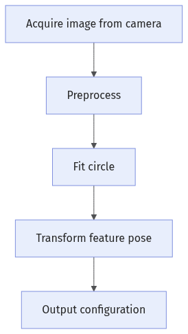
Take the circle measurement project (Y4 datum) as an example. The structure of this Mech-MSR project is shown below:
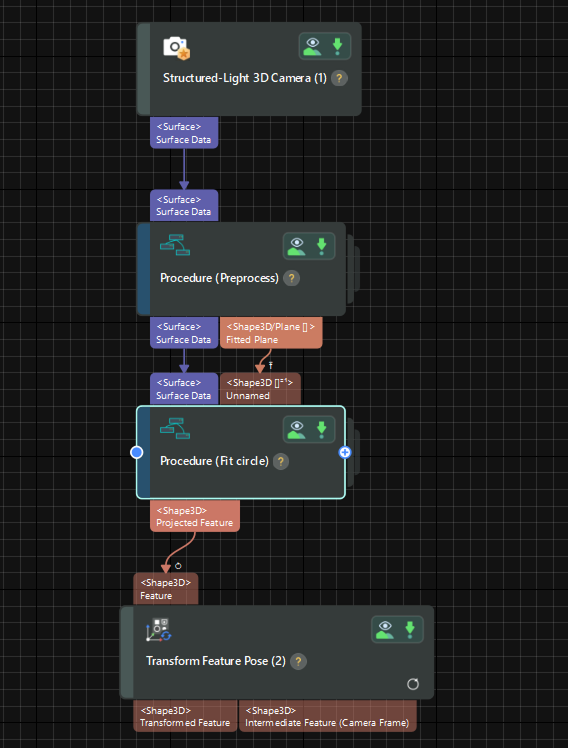
This demo project contains the following five steps:
Each step is briefly explained below, together with key debugging focus points.
| During debugging, enable Debug Output above the 3D view to observe processing results of each step. In production environments, it is recommended to disable this option to improve performance. |
Acquire Image from Camera
Use the "Structured-Light 3D Camera" step to acquire images and process them into surface data. Usually, this step does not need modification.
If the field of view is not suitable during first point debugging, you can temporarily use automatic projection-parameter calculation: select the "Structured-Light 3D Camera" step and enable Automatically calculate projector parameters in the step parameter panel.
| After project execution, this option is automatically unchecked and remains off in subsequent runs. It is recommended to use this option during first debugging for quick validation, then keep it off in later debugging to reflect real measurement conditions more accurately. |
Preprocess
Extract surface data in 3D ROI and fit a reference plane. This step uses a Procedure to implement preprocessing. You can double-click to view detailed configuration and processing content of each substep.
The preprocess Procedure includes the following substeps:
-
Process Surface by Filter
Purpose: select 3D ROI of measurement points and extract required surface data.
Modify "Region Type" according to actual hole conditions. A cuboid or cylinder is usually sufficient. To adjust region size, hold Ctrl and drag with mouse.
In the 3D data view, if it is inconvenient to adjust feature regions in Perspective Mode, switch to Surface Mode or Profile Mode. 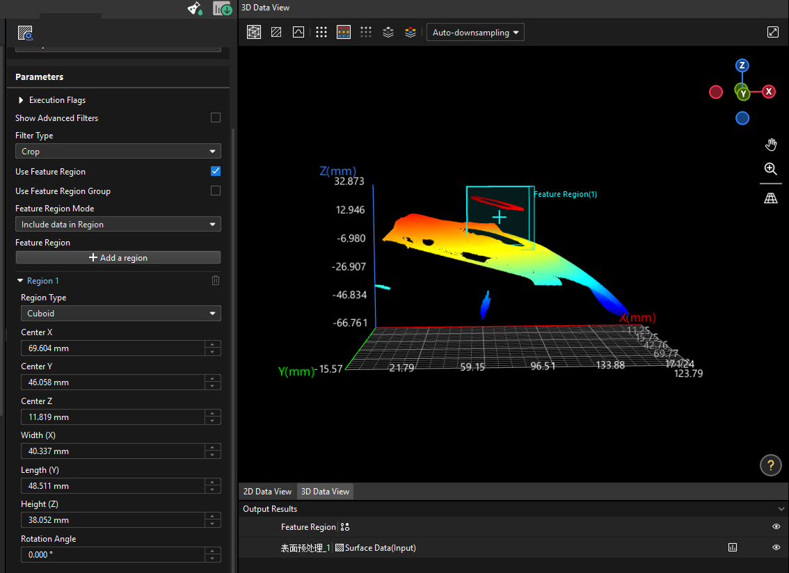
-
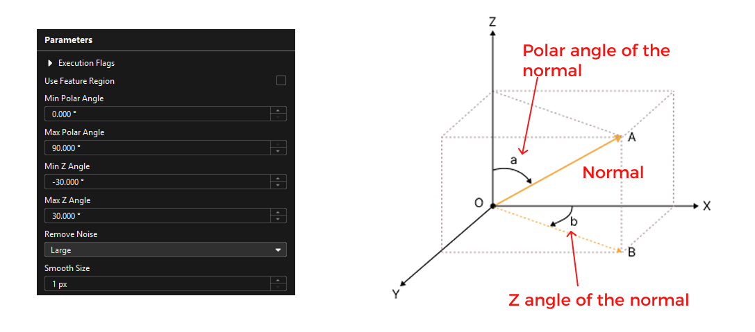
Filter Surface Points by Normals
Purpose: filter surface and edge noise and extract plane points.
Normals of surface noise are usually different from plane normal, so you can adjust normal-vector angles to filter points deviating from the plane, especially the "Min Z Angle" as shown below. If needed, combine with the "Remove Noise from Surface" step.
-
Fit Plane to Surface
Purpose: fit a plane as the reference plane for subsequent features.
This step usually does not need modification.
Fit Circle
Fit the circle in the feature region. This step uses a Procedure to implement circle fitting. You can double-click to view detailed configuration and processing content of each substep.
The circle fitting Procedure includes the following substeps:
-
Transform Surface
Purpose: transform surface data from tilted state to horizontal state for subsequent noise removal and circle fitting.
Usually no modification is required.
-
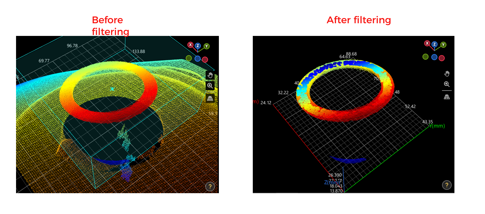
Remove Noise from Surface
Purpose: remove part of surface noise while keeping edge features.
Adjust the "Depth Difference Threshold" parameter and check effect in the 3D data view.
-
Fit Circle to Surface Edge
Purpose: fit a circle based on edge changes.
Mainly adjust the feature region and keep other parameters unchanged from the demo project. In the 3D data view, you can switch viewpoints to inspect results.
In Perspective Mode, it is normal that the fitted circle (green) appears below the hole. A later step projects the circle back to the reference plane. -
Transform Feature Pose
Purpose: restore the feature from horizontal state to the original tilted state.
Usually no modification is required.
-
Project Feature to Plane
Purpose: project feature back to the reference plane.
Usually no modification is required.
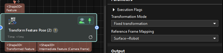
Transform Feature Pose
Use the "Transform Feature Pose" step to convert circle pose from the surface-data reference frame to the robot reference frame. Because the robot reference frame is fixed, feature poses are usually transformed into robot coordinates before being sent out, to unify feature coordinates.
Output Configuration
In the toolbar of Mech-MSR, click Output Management.
-
Under the Communication output tab, confirm current mode is "inline measurement".
-
In the Output area, confirm that output measurement item is the "Transformed Feature" port of the "Transform Feature Pose" Step, and that the Communication key parameter is configured.
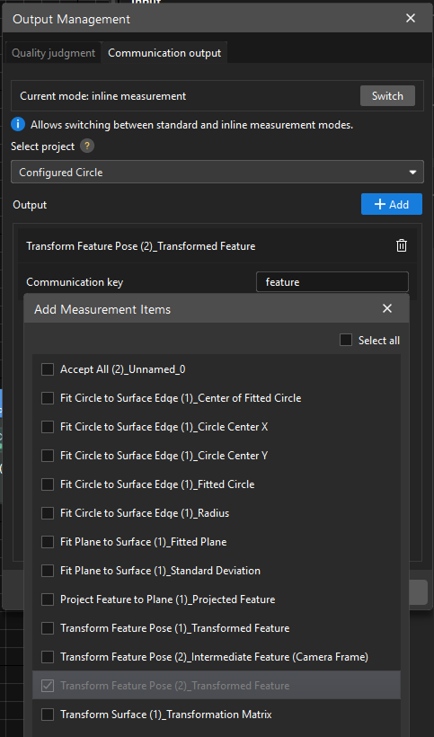
- How to set communication keys?
-
If the measurement project outputs only one feature (measurement item), communication key can be set to "feature".
If the measurement project outputs one feature and one GD&T, set communication key of the feature to "feature" and communication key of GD&T to "gdt". Check the "Slot with flatness" example project to understand communication key settings for one feature + one GD&T.
If the measurement project outputs multiple features and GD&Ts, communication key of each feature must be set to the feature name configured in Mech-Metrics, and communication key of each GD&T must be set to the GD&T name configured in Mech-Metrics. In other words, communication keys must match feature/GD&T names configured in Mech-Metrics, so that Mech-Metrics can correctly distinguish data of different features and GD&Ts. Check the "Slot pair" example project to understand communication key settings for multiple features and GD&Ts.
For custom controls of features, communication keys must match custom control names configured in Mech-Metrics. Check the "Circle with error-proofing" example project to understand communication key settings for custom control items.
15-Minute Minimal Exercise
It is recommended to first do a minimal exercise of "adding a circle feature" to avoid being able to run validation only without independent operation capability:
-
In Mech-MSR, copy an existing circle sample project, create a new measurement project, and adjust feature region for the new measurement point.
-
In Mech-Metrics, add a new circular feature and bind it to the newly created measurement project. Refer to Create and Modify a Feature.
-
Configure feature ID for this feature to ensure accurate invocation during communication triggering.
-
Add a new feature measurement command in the communication simulator.
-
Click Add Command, select "measureFeature" in the popup dialog, and click OK.
-
Double-click to rename the new command and configure parameter values, especially ensure feature ID is consistent with the ID of the new circular feature in Mech-Metrics.
-
Use Move Up to place the new command between start-measurement and end-measurement commands.
-
-
Run simulation again and judge success by the following criteria:
-
The newly added circular feature in Mech-Metrics can be triggered normally without obvious errors.
-
Adjusted ROI and feature region in Mech-MSR can stably cover target measurement points.
-
Compared with before modification, the new feature has measurable results, or existing results change as expected.
-
Current objective is only to get familiar with software operation, so it is unnecessary to build a measurement project from scratch. It is usually more efficient to copy and modify an existing demo project.
FAQ: How to Quickly Judge Whether Results Are Roughly Correct?
During first debugging, you can quickly evaluate by the following two methods:
-
Check 3D view: in feature-fitting related steps, verify whether fitted features align with actual contours. If fitted contours clearly deviate from actual hole positions or edges, ROI, feature regions, or filtering conditions usually still need adjustment.
-
Check output data: view intermediate feature data in Transform Feature Pose step and verify whether key coordinate values are in a reasonable range. This method is more suitable for quickly identifying obvious abnormalities.
These two methods do not replace formal acceptance, but can be used to quickly judge whether the current project has basic correctness.
From Demo to Production
| What You Want to Do | Recommended Documentation |
|---|---|
Deploy a complete inline measurement solution |
|
Create Mech-MSR solution and measurement project |
|
Create Mech-Metrics project |
|
Configure part alignment |
|
Configure and maintain measurement features |
|
Analyze historical measurement data |
Next Learning Path
-
Continue reading Inline Measurement Solution Deployment to build a systematic understanding of the overall project.
-
Enter Mech-Metrics Operation Guide as needed for feature-level configuration.
-
Complete Repeatability Validation and Correlation Analysis and Compensation before system go-live.