Create a New Part and Configure Part Properties
This section introduces how to create a new part in the Mech-Metrics and configure the properties of the part, including its association with the Mech-MSR project.
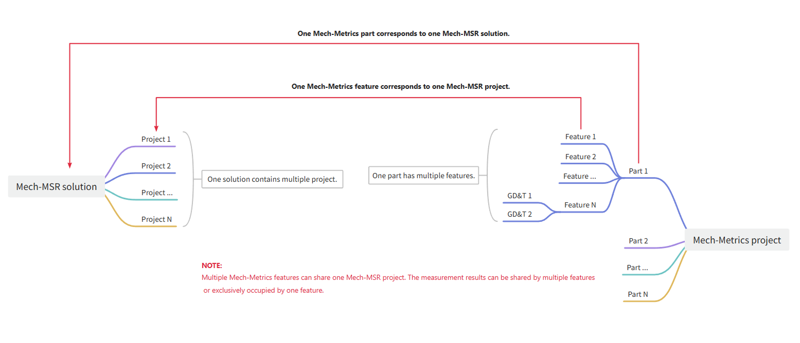
Relationship Between Mech-Metrics Part and Mech-MSR Project
In an inline measurement system, the Mech-MSR project defines the complete measurement task and workflow (including measurement solution, measurement items, reference frame, data acquisition, etc.), while the Mech-Metrics parts are the objects that are actually measured and managed under these measurement processes and standards (such as subframes, steering arms, etc.).
-
A Mech-MSR project can serve multiple part instances (in different SNs/batches). Mech-Metrics manages and displays the attributes, measurement data, and results of these parts.
-
When you use Mech-Metrics, you need to associate a part with the corresponding Mech-MSR solution.
Create a New Part
In the upper-left corner of the Configuration interface, you can see a Part01 tab, which is the part automatically created for the current project. The default name of the first created part is Part01. You can modify the name of the part according to the actual situation. This part name is used for Command 801: Start Measurement Task in the robot program.
| If you want to change the name of a part, you can right-click the part name in the Part tab or the resource tree and select Rename to change it. |
|
Part IDs are identification codes used to distinguish different part types. Each part type corresponds to a unique part ID, which facilitates classification, management, and query in the system. You can configure a unique part ID for each part type according to the actual requirement. In the measurement commands (801 to 805) of the robot program, use this part ID to identify the part type.
|
Configure Part Properties
After creating a new part, you need to configure the relevant properties of the part to associate it with the measurement process of the Mech-MSR.
In the resource tree on the left of the interface, click the part name in the part area, and the parameter panel on the right will display the property configuration area of the part, including part class and Mech-MSR solution.
Select Part Class
In the Part class area, select the part class:
-
Part: The object to be measured. In most cases, please select the part.
-
Thermal drift rod: used to acquire compensation data for thermal drift.
If thermal drift rod is selected, please complete the following configurations to enable thermal drift compensation:
-
Create features for the drift rod in Mech-Metrics, and assign corresponding Mech-MSR projects and parameter recipes to each feature.
-
Use the thermal drift compensation tool in Mech-MSR to associate the robot with the project and select whether to enable thermal drift compensation for each project.
-
Associate the Mech-MSR Solution
In the Mech-MSR solution area, associate the corresponding Mech-MSR solution path to the part.
| Each Mech-Metrics part can only be associated with one Mech-MSR solution. |
You can use the following methods to associate a solution:
-
Manually select a solution path: Click the folder icon to the right of the Solution path, and browse for and select a Mech-MSR solution path.
-
Auto fetch path: Ensure that the Mech-MSR solution corresponding to the part is opened in Mech-MSR, and then click Fetch current solution path from Mech-MSR. The software will automatically obtain and enter the path of the currently opened solution.
In addition, you need to complete the following configurations:
-
Import CAD model: Import a CAD file for the part as a reference for subsequent measurement point definition and result display. For details, refer to Import CAD Reference Objects to Parts.
-
Configure Part ID: Specify a unique part ID for each type of part, which facilitates the recognition of different parts during robot communication. For details, refer to Configure Part ID.