Use RPS Alignment
This section introduces how to use RPS Alignment.
To use RPS Alignment, perform the following operations:
-
You can open the RPS Alignment dialog box in either of the following ways and add features to use:
-
In the upper functional area of the Configuration interface, select . In the pop-up dialog box, click + next to Basis features and add features as needed.
-
You can also hold the Ctrl key and click to select multiple features in the left-side resource tree of the current part, and then right-click and select .
You can view the part’s drawing to identify the RPS features that need to be selected. -
-
After you add the features, select features in the table below Basis features.
You can view the part’s drawing and determine the required features based on the 3-2-1 rule. 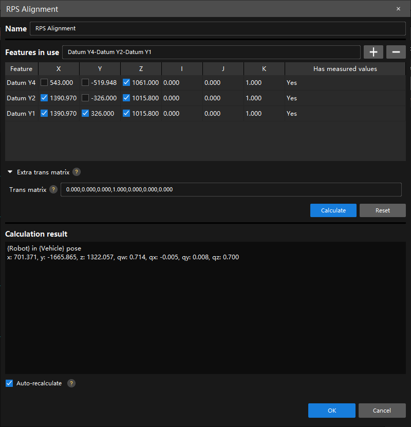
3-2-1 rule
In RPS, the 3-2-1 rule is used to constrain the six degrees of freedom of a part. Specifically, the part has three dimensions in 3D space—x, y, and z—each with two directions (movement and rotation), making a total of six degrees of freedom. The 3-2-1 rule constrains the part using the following reference points:
-
Three reference points forming a plane constrain the part’s movement along the z-axis and its rotation around the x-axis and y-axis.
-
Two reference points forming a line constrain the part’s movement along the y-axis and its rotation around the z-axis.
-
One reference point constrains the part’s movement along the x-axis.
-
-
Select Auto-recalculate and click OK.
Since there is no measurement data at this point, you do not need to click Calculate. After you select Auto-recalculate, the software will automatically recalculate once all the measurement data for the selected features is obtained. How to determine whether the calculation result is valid?
Obtain the measured values for a feature, and then check the deviation values for that feature on the annotation card. If the deviation values are not highlighted in red, it indicates that the alignment is valid.
Managing Alignment Methods
After an alignment method is created, click the alignment method in the resource tree on the left to view and manage its configuration in the parameter panel on the right. The parameter panel consists of three parts: Basic Info, Alignment Result, and Scope Features.
You can also right-click the alignment method in the resource tree and then select Modify to open the alignment dialog box and modify its configuration.
This section covers the following content:
Activating and Deactivating Alignment Methods
In the Basic Info section of the parameter panel, select Activate to activate the alignment method, or clear it to deactivate the alignment method.
|
Viewing and Exporting Alignment Results
The Alignment Result section of the parameter panel displays the Translation and Rotation results of the alignment.
-
Click Copy Result to copy the alignment result.
-
Click Export Result, and the software will export the alignment result to the specified path.
-
Export Path: Click Browse… to select the export path.
-
Auto Export: If selected, the software will automatically export the alignment result.
-
Configuring Scope Features
Scope features are used to specify the features that the current alignment method applies to.
In the Scope Features section of the parameter panel, click Edit Scope Features to open the Edit Scope Features dialog box. In this dialog box:
-
You can search for features in the Search features box, or click Select all or Deselect all to select features in batches.
-
Available features are all the features that the current alignment method can apply to. Among them, the basis features that constitute the alignment method are always selected and cannot be changed.
-
Unavailable features are features that have been occupied by other alignment methods and cannot be selected.
|
Click the alignment overview entry in the resource tree to open the Alignment Overview, where you can centrally view the scope features of each alignment method. |