Create and Modify a Feature
After you import the part model and associate a Mech-MSR solution for the part, you need to create a feature for the part. This section describes how to create, modify, and delete a feature.
Create a Feature
The software can create the following ten features: circle, slot, cylinder, point, line, plane, rectangle, pattern, distance, and angle. Determine the type and number of features to be created according to the actual measurement requirements.
Create a Circle Feature
Please follow the steps below to create a circle feature:
-
On the Mech-Metrics Configuration interface, under the Feature tab, click Circle.
-
In the Create Circle Feature dialog box, set the following information:
-
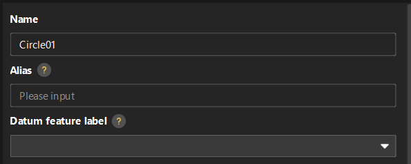
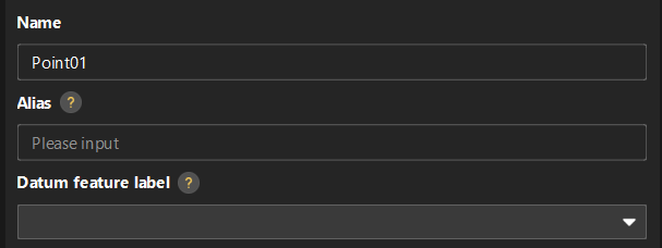
Set Name, Alias, and Datum feature label based on actual situation.
-
Alias: Used to associate the measurement item name in the CMM report.
-
Datum feature label: When this feature is used as the datum feature, it needs to be labeled. Datum feature labels are used in GD&T controls. For more information, see Configure GD&T Control Items.
-
-
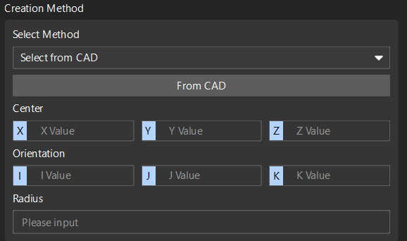
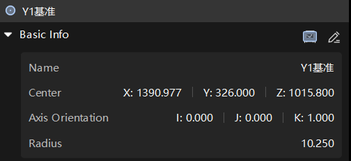
Set the creation method: The Select method is Select from CAD by default. Input Center (X, Y, Z), Orientation (I, J, K) and Radius.
-
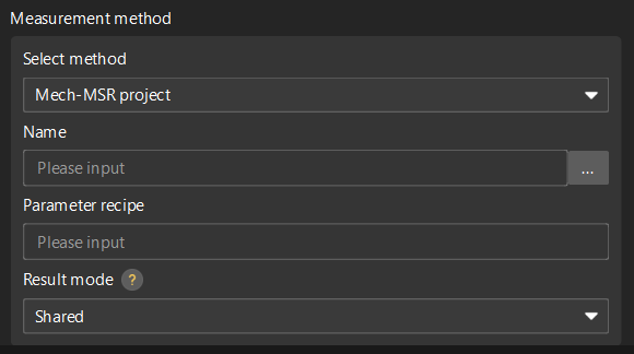
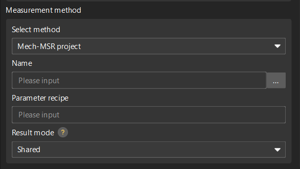
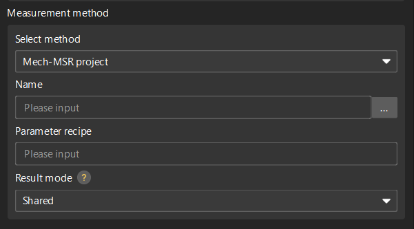
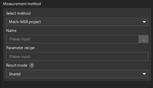
Set the measurement method: The Select method is Mech-MSR project by default. Select the project corresponding to the feature in the drop-down list of the Name, and set the Parameter recipe and Result mode according to needs.
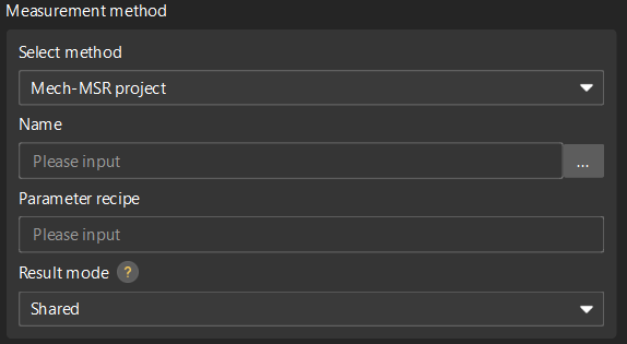
Result mode: Set the method to use the measurement result of the feature binding project.
-
Shared: When a feature-bound project finishes running, all features bound to the project will parse the measurement results.
-
Exclusive: When the project bound by a feature finishes running, only the feature that triggered the project to run will parse the measurement result.
-
-
-
Click OK.
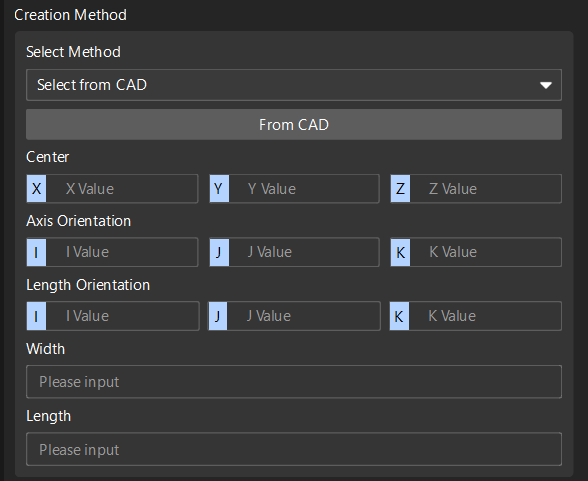
Create a Slot Feature
Follow the steps below to create a slot feature:
-
In the Configuration interface of Mech-Metrics, under the Feature tab, click Slot.
-
In the Create Slot Feature dialog box, set the following information:
-
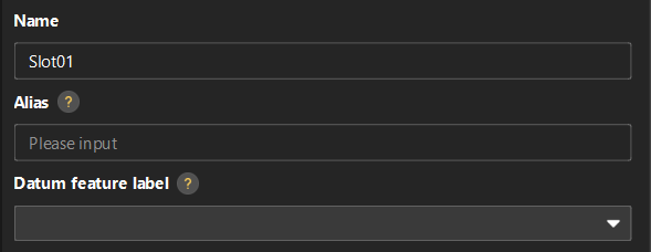
Set Name, Alias, and Datum feature label based on actual situation.
-
Alias: Used to associate the measurement item name in the CMM report.
-
Datum feature label: When this feature is used as the datum feature, it needs to be labeled. Datum feature labels are used in GD&T controls. For more information, see Configure GD&T Control Items.
-
-
Set the creation method: The Select method is Select from CAD by default. Input Center (X, Y, Z), Axis Orientation (I, J, K), Length Orientation (I, J, K), Width and Length.
-
Set the measurement method: The Select method is Mech-MSR project by default. Select the project corresponding to the feature in the drop-down list of the Name, and set the Parameter recipe and Result mode according to needs.
Result mode: Set the method to use the measurement result of the feature binding project.
-
Shared: When a feature-bound project finishes running, all features bound to the project will parse the measurement results.
-
Exclusive: When the project bound by a feature finishes running, only the feature that triggered the project to run will parse the measurement result.
-
-
-
Click OK.
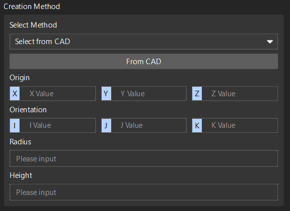
Create a Cylinder Feature
Please follow these steps to create a cylinder feature:
-
On the Mech-Metrics Configuration interface, under the Feature tab, click Cylinder.
-
In the Create Cylinder Feature dialog box, set the following information:
-
Set Name, Alias, and Datum feature label based on actual situation.
-
Alias: Used to associate the measurement item name in the CMM report.
-
Datum feature label: When this feature is used as the datum feature, it needs to be labeled. Datum feature labels are used in GD&T controls. For more information, see Configure GD&T Control Items.
-
-
Set the creation method: The Select method is Select from CAD by default. Input Origin (X, Y, Z), Orientation (I, J, K), Radius and Height.
-
Set the measurement method: The Select method is Mech-MSR project by default. Select the project corresponding to the feature in the drop-down list of the Name, and set the Parameter recipe and Result mode according to needs.
Result mode: Set the method to use the measurement result of the feature binding project.
-
Shared: When a feature-bound project finishes running, all features bound to the project will parse the measurement results.
-
Exclusive: When the project bound by a feature finishes running, only the feature that triggered the project to run will parse the measurement result.
-
-
-
Click OK.
Create a Point Feature
Follow the steps below to create a point feature:
-
In the Configuration interface of Mech-Metrics, under the Feature tab, click Point.
-
In the Create Point Feature dialog box, set the following information:
-
Set Name, Alias, and Datum feature label based on actual situation.
-
Alias: Used to associate the measurement item name in the CMM report.
-
Datum feature label: When this feature is used as the datum feature, it needs to be labeled. Datum feature labels are used in GD&T controls. For more information, see Configure GD&T Control Items.
-
-
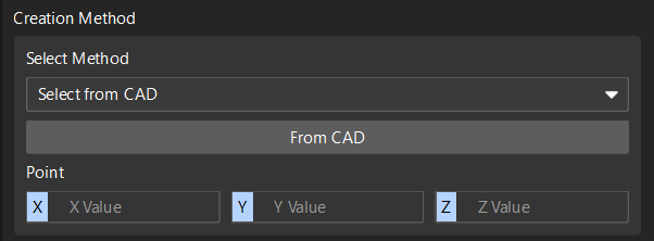
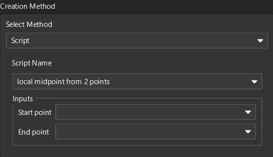
Set the method for creating (either):
-
Select from CAD: Enter the coordinates of the point (X, Y, Z).
-
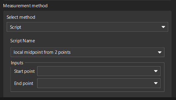
Script: Select a script name, and enter the start point and end point.
-
-
Set the measurement method (either):
-
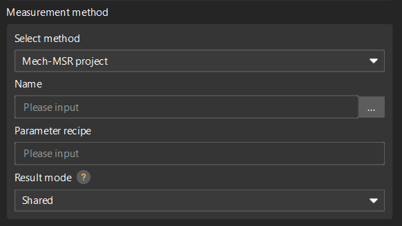
Mech-MSR project: Select the project corresponding to the feature in the drop-down list of the Name, and set the Parameter recipe and Result mode according to actual needs.
Result mode: Set the method to use the measurement result of the feature binding project.
-
Shared: When a feature-bound project finishes running, all features bound to the project will parse the measurement results.
-
Exclusive: When the project bound by a feature finishes running, only the feature that triggered the project to run will parse the measurement result.
-
-
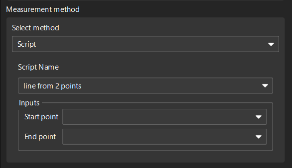
Script: Select the corresponding measurement script.
-
-
-
Click OK.
Create a Line Feature
Follow the steps below to create a line feature:
-
In the Configuration interface of Mech-Metrics, under the Feature tab, click Line.
-
In the Create Line Feature dialog box, set the following information:
-
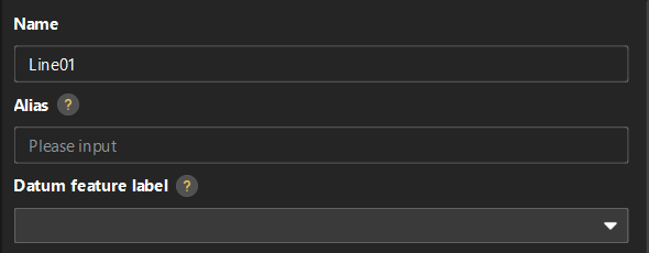
Set Name, Alias, and Datum feature label based on actual situation.
-
Alias: Used to associate the measurement item name in the CMM report.
-
Datum feature label: When this feature is used as the datum feature, it needs to be labeled. Datum feature labels are used in GD&T controls. For more information, see Configure GD&T Control Items.
-
-
Set the method for creating (either):
-
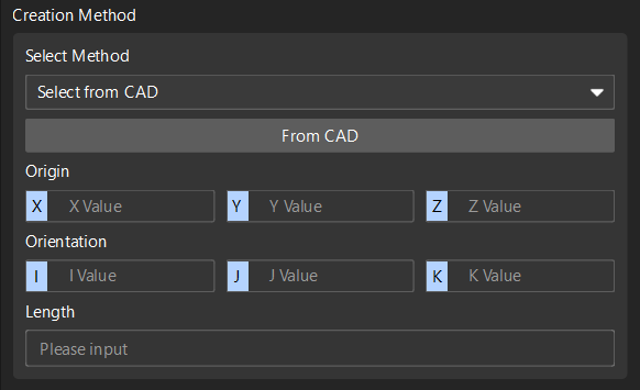
Select from CAD: Input Origin (X, Y, Z), Orientation (I, J, K) and Length.
-
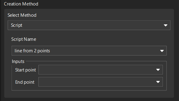
Script: Select the script Create line from two points, and input the start point and end point.
-
-
Set the measurement method (either):
-
Mech-MSR project: Select the project corresponding to the feature in the drop-down list of the Name, and set the Parameter recipe and Result mode according to actual needs.
Result mode: Set the method to use the measurement result of the feature binding project.
-
Shared: When a feature-bound project finishes running, all features bound to the project will parse the measurement results.
-
Exclusive: When the project bound by a feature finishes running, only the feature that triggered the project to run will parse the measurement result.
-
-
Script: Select the corresponding measurement script.
-
-
-
Click OK.
Create a Plane Feature
Follow these steps to create a plane feature:
-
In the Configuration interface of Mech-Metrics, under the Feature tab, click Plane.
-
In the Create Plane Feature dialog box, set the following information:
-
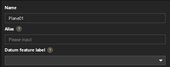
Set Name, Alias, and Datum feature label based on actual situation.
-
Alias: Used to associate the measurement item name in the CMM report.
-
Datum feature label: When this feature is used as the datum feature, it needs to be labeled. Datum feature labels are used in GD&T controls. For more information, see Configure GD&T Control Items.
-
-
Set the method for creating (either):
-
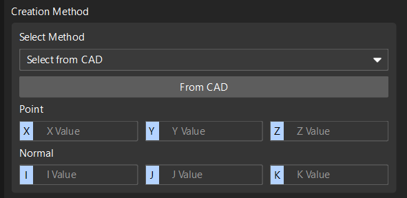
Select from CAD: Input point (X, Y, Z) and normal (I, J, K).
-
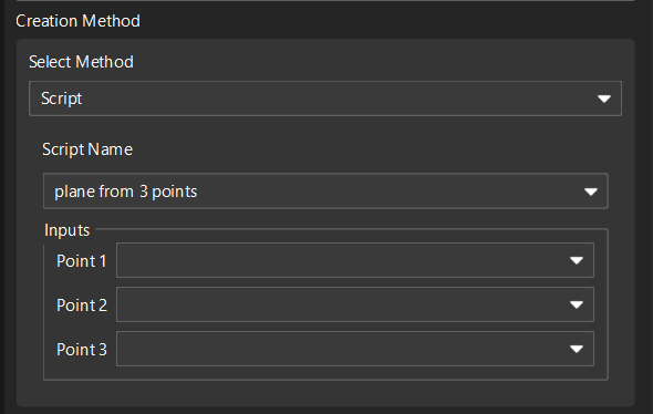
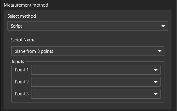
Script: Select the script Create plane from three points, and input the coordinates of the three points.
-
-
Set the measurement method (either):
-
Mech-MSR project: Select the project corresponding to the feature in the drop-down list of the Name, and set the Parameter recipe and Result mode according to actual needs.
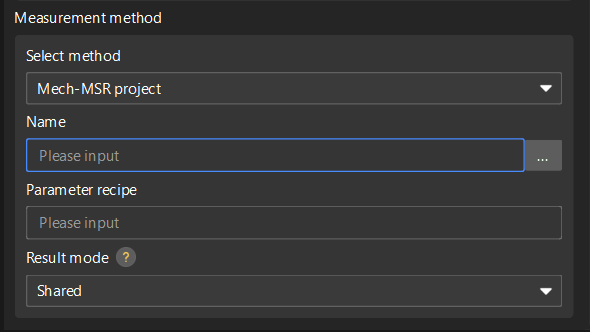
Result mode: Set the method to use the measurement result of the feature binding project.
-
Shared: When a feature-bound project finishes running, all features bound to the project will parse the measurement results.
-
Exclusive: When the project bound by a feature finishes running, only the feature that triggered the project to run will parse the measurement result.
-
-
Script: Select the corresponding measurement script.
-
-
-
Click OK.
Create a Rectangle Feature
Follow these steps to create a rectangle feature:
-
In the Configuration interface of Mech-Metrics, under the Feature tab, click Rectangle.
-
In the Create Rectangle Feature dialog box, set the following information:
-
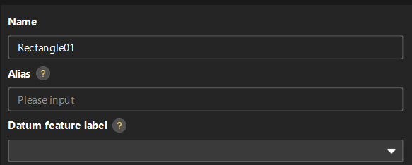
Set Name, Alias, and Datum feature label based on actual situation.
-
Alias: Used to associate the measurement item name in the CMM report.
-
Datum feature label: When this feature is used as the datum feature, it needs to be labeled. Datum feature labels are used in GD&T controls. For more information, see Configure GD&T Control Items.
-
-
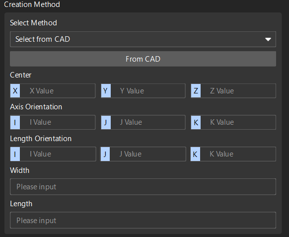
Set the creation method: Only Select from CAD is available. Input the following parameters:
-
Center: X, Y, Z
-
Axis Orientation: I, J, K
-
Length Orientation: I, J, K
-
Width and Length
-
-
Set the measurement method: Only Mech-MSR project is available. Select the project corresponding to the feature in the drop-down list of the Name, and set the Parameter recipe and Result mode according to actual needs.
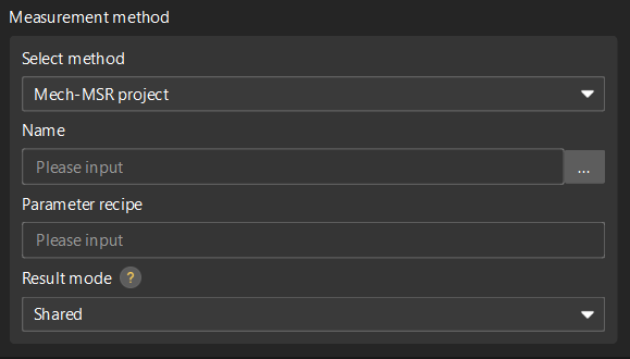
Result mode: Set the method to use the measurement result of the feature binding project.
-
Shared: When a feature-bound project finishes running, all features bound to the project will parse the measurement results.
-
Exclusive: When the project bound by a feature finishes running, only the feature that triggered the project to run will parse the measurement result.
-
-
-
Click OK.
Create a Pattern Feature
Follow these steps to create a pattern feature:
-
In the Configuration interface of Mech-Metrics, under the Feature tab, click Pattern.
-
In the Create Pattern Feature dialog box, set the following information:
-
Set Name and Alias.
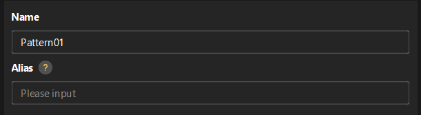
Alias: Used to associate the measurement item name in the CMM report.
-
In the Select features area, select the desired features.
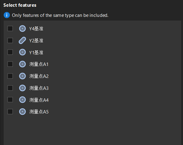
Only features of the same type can be selected for a pattern.
-
-
Click OK.
Create a Distance Feature
Follow the steps below to create a distance feature:
-
In the Configuration interface of Mech-Metrics, under the Feature tab, click Distance.
-
In the Create Distance Feature dialog box, set the following information:
-
Set Name and Alias.
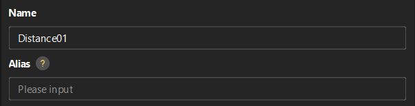
Alias: Used to associate the measurement item name in the CMM report.
-
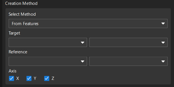
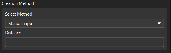
Set the method for creating (either):
-
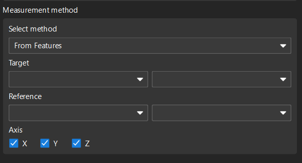
From Features: Select the Target and Reference, and select the Axis (X, Y, Z) according to needs.
-
Manual input: Enter the distance directly.
-
-
Set the measurement method (either):
-
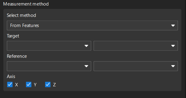
From Features: Select the Target and Reference, and then select the Axis.
-
Mech-MSR project: Select the project corresponding to the feature in the drop-down list of the Name, and set the Parameter recipe and Result mode according to actual needs.
Result mode: Set the method to use the measurement result of the feature binding project.
-
Shared: When a feature-bound project finishes running, all features bound to the project will parse the measurement results.
-
Exclusive: When the project bound by a feature finishes running, only the feature that triggered the project to run will parse the measurement result.
-
-
-
-
Click OK.
Create an Angle Feature
Follow these steps to create an angle feature:
-
In the Configuration interface of Mech-Metrics, under the Feature tab, click Angle.
-
In the Create Angle Feature dialog box, set the following information:
-
Set Name and Alias.
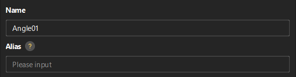
Alias: Used to associate the measurement item name in the CMM report.
-
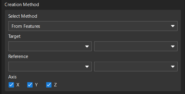
Set the method for creating (either):
-
From Features: Select the Target and Reference, and select the Axis (X, Y, Z) according to needs.
-
Manual input: Input the angle directly.
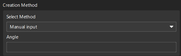
-
-
Set the measurement method (either):
-
From Features: Select the Target and Reference, and then select the Axis.
-
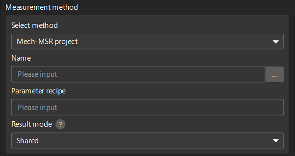
Mech-MSR project: Select the project corresponding to the feature in the drop-down list of the Name, and set the Parameter recipe and Result mode according to actual needs.
Result mode: Set the method to use the measurement result of the feature binding project.
-
Shared: When a feature-bound project finishes running, all features bound to the project will parse the measurement results.
-
Exclusive: When the project bound by a feature finishes running, only the feature that triggered the project to run will parse the measurement result.
-
-
-
-
Click OK.
Modify a Feature
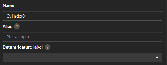
The first created circle feature is named Circle01 by default. To modify the configurations of the created Circle01 feature, perform the following operations:
-
Click Circle01 in the resource tree. In the Basic Info section on the right parameter panel, click the edit button
 .
.
-
In the feature creation dialog box, modify configurations of the feature (such as the name or nominal values of the feature) and click OK.
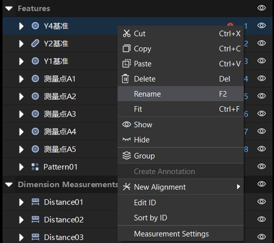
Delete a Feature
The first created circle feature is named Circle01 by default. For example, to delete the Circle01 feature, use one of the following methods:
-
Right-click Circle01 in the resource tree and select Delete.
-
Click Circle01 in the resource tree, and then press the Delete key.