TCP Standard Interface Commands
This section introduces the TCP Standard Interface commands supported by the inline measurement system. The TCP Standard Interface commands are used to establish TCP communication between the robot and the inline measurement system.
Command Overview
| Command name | Calling sequence | Required | Description |
|---|---|---|---|
- |
No |
Used to switch projects in the Mech-Metrics. |
|
① |
Yes |
Use the robot or external device to inform the Mech-Metrics to start measuring the new part, and send the part name, part SN, and other part information to Mech-Metrics. |
|
② |
Yes |
This command triggers the Mech-MSR project that corresponds to the to-be-measured feature to run. To perform multiple measurements, call this command multiple times. |
|
④ |
Yes |
Use the robot or an external device to inform the Mech-Metrics that the measurement ends and request the measurement result of the part. |
|
③ |
No |
In some scenarios, the part SN cannot be obtained at the beginning of measurement. For example, it needs to be scanned during measurement. This command is used to input the part SN during the measurement. |
|
⑥ |
No |
Input the part SN to allow the main interface of Mech-Metrics to display the data view of the part. |
|
- |
Yes |
Used for robot calibration process control and status query. When calling the command, calibration status parameters are passed in to restart the calibration or add calibration points. The command returns the current calibration status, the flange pose of the next calibration point, and the joint positions. |
|
The command transmission methods supported by the inline measurement system are shown in the figure below: 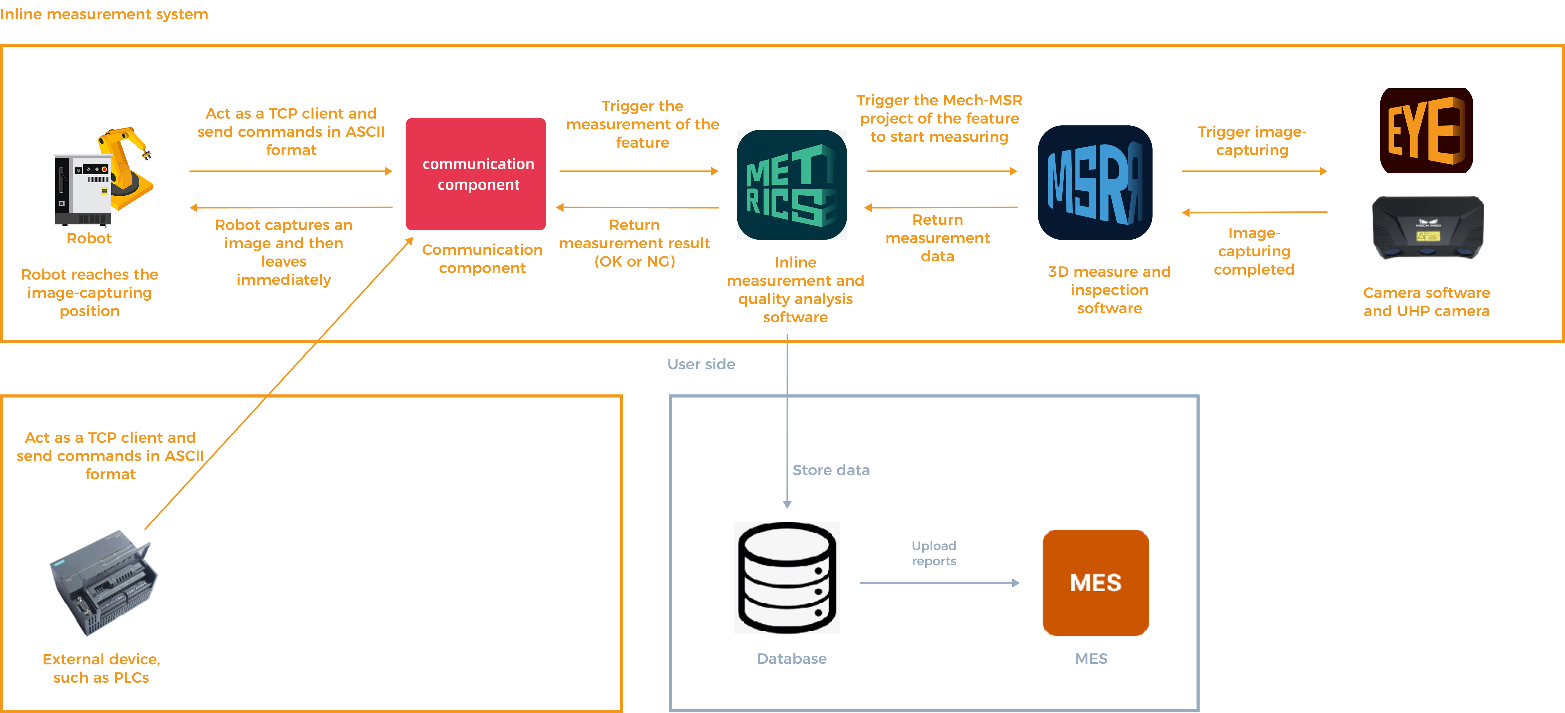
The explanation is as follows:
|
Communication Commands
Command 800: Switch Project
Send Command
Sender
Robot or external device (such as a PLC)
Receiver
Mech-Metrics
Time to Send
Before switching the project.
Command Description
The robot or external device informs the Mech-Metrics to start switching projects.
Command Format
800, part ID, project IDSample Command
800,1,1Command Parameter Description
| Parameter | Required | Description |
|---|---|---|
Part ID |
Yes |
This parameter specifies the unique identification of the part type. The part ID is an integer between 1 and 99. The specified part ID must have been configured in the Configure Part ID window.
|
Project ID |
Yes |
This parameter specifies the ID of the project to be switched. The specified project ID must have been configured through project switching rules.
|
Return Command
Sender
Mech-Metrics
Receiver
Robot or external device (such as a PLC)
Time to Send
The sent command is received.
Command Description
The Mech-Metrics informs the robot that it has received the command to switch to a new project, starts switching to the new project, and then informs the robot whether the switch was successful.
Command Format
800, status codeSample Command
800,8105Command Parameter Description
| Parameter | Description |
|---|---|
status code |
This parameter indicates the status code that indicates the command execution result.
In the above example, the status code returned by Mech-Metrics is 8105, which indicates that the command execution succeeds. |
Command 801: Start Measurement Task
Send Command
Sender
Robot or external device (such as a PLC)
Receiver
Mech-Metrics
Time to Send
This command is sent when the measurement of a new part begins.
Command Description
The robot or external device informs the Mech-Metrics to start measuring a new part.
Command Format
801, part ID, part name, part SN, quality inspection mode, custom 1, custom 2, custom 3, custom 4, custom 5, custom 6, custom 7, custom 8Sample Command
801,1,part01,sn001,2,1,2,3,4,5,6Command Parameter Description
| Parameter | Required | Description |
|---|---|---|
Part ID |
Yes |
This parameter specifies the unique identification of the part type. The part ID is an integer between 1 and 99. The specified part ID must have been configured in the Configure Part ID window. In the above example, the first 1 is the part ID. |
Part name |
Yes |
This parameter specifies the name of the part to be measured. The part name can contain letters and digits and cannot exceed 20 characters in length. In the above example, part01 is the part name. |
part SN |
Yes |
This parameter specifies the part SN. The part SN, also known as the part serial number, is the unique identifier of the part. The part SN can contain letters and digits and cannot exceed 30 characters in length. In the above example, sn001 is the part SN. This parameter is required. In some scenarios, the part SN cannot be obtained at the start of measurement and may need to be obtained by scanning a barcode or QR code during the measurement process. In these cases, the part SN can be empty but the position of the part SN must be reserved. Example: 801,1,part01,,1,2,3,4,5,6. In this example, the part SN is not specified but the position of the part SN is reserved by the comma (,). |
quality inspection mode |
Yes |
This parameter specifies the quality inspection mode of the part. 1: Full inspection, which is to detect all dimensions of the part; 2: Partial inspection, which is to detect key dimensions of the part. 0: Use the current configuration. In the preceding example, the first 2 represents that the quality inspection mode is partial inspection. |
custom 1-8 |
No |
This parameter is optional. This parameter provides custom information of the part. Custom parameters are used only when more part information needs to be provided to Mech-Metrics. This command supports up to 8 custom parameters. The value of each custom parameter is an integer between 1 and 8. To use a custom parameter:
In the above example, 1,2,3,4,5,6 are custom parameters. The meaning of each of these custom parameters is configured in Mech-Metrics. |
Return Command
Sender
Mech-Metrics
Receiver
Robot or external device (such as a PLC)
Time to Send
The sent command is received.
Command Description
Mech-Metrics informs the robot that it has received the start measurement task command, begins creating a historical record for the new part, and informs the robot whether this execution will be continuous or a single run.
Command Format
801, status code, continuous execution/single executionSample Command
801,8100,1Command Parameter Description
| Parameter | Description | ||||
|---|---|---|---|---|---|
status code |
This parameter indicates the status code that indicates the command execution result.
In the above example, the status code returned by Mech-Metrics is 8100, which indicates that the command execution succeeds. |
||||
continuous execution/single execution |
This parameter indicates whether the execution is continuous execution or single execution.
In the above example, 1 indicates continuous execution.
|
Command 802: Run Feature Measurement
Send Command
Sender
Robot or external device (such as a PLC)
Receiver
Mech-Metrics
Time to Send
The robot reaches the feature’s image-taking position.
Command Description
This command triggers the Mech-MSR project that corresponds to the to-be-measured feature to run.
Command Format
802, part ID, feature ID, robot joint positions, robot flange poseSample Command
802,1,1,10,20,30,40,50,60,100,200,300,0,180,0Command Parameter Description
| Parameter | Required | Description | ||
|---|---|---|---|---|
Part ID |
Yes |
This parameter specifies the unique identification of the part type. The part ID is an integer between 1 and 99. The specified part ID must have been configured in the Configure Part ID window. In the above example, the first 1 is the part ID. |
||
feature ID |
Yes |
This parameter specifies the ID of the feature to be measured. The ID is the unique identifier of the feature. The ID is an integer between 1 and 999.
In the above example, the second 1 is the feature ID. |
||
robot joint positions |
Yes |
This parameter specifies the joint positions of the robot. In general, six joint positions (J1 to J6) of the robot are specified, in degrees. In the above example, 10,20,30,40,50,60 are the joint positions of the robot. |
||
robot flange pose |
Yes |
This parameter specifies the pose of the robot flange. It typically includes six values: three for position and three for orientation. The unit of position data is millimeters. The orientation data is represented using Euler angles, with the unit in degrees. In the example above, 100,200,300,0,180,0 represent the robot flange pose, where 100,200,300 are position data, and 0,180,0 are orientation data. |
Return Command
Sender
Mech-Metrics
Receiver
Robot or external device (such as a PLC)
Time to Send
Mech-Metrics receives a signal indicating that the camera has completed taking the photo.
Command Description
Notify the robot that the image has been taken, so it can move to the next measurement position.
Command Format
802, status codeSample Command
802,8101Command Parameter Description
| Parameter | Description |
|---|---|
status code |
This parameter indicates the status code that indicates the command execution result.
In the above example, the status code returned by Mech-Metrics is 8101, which indicates that the command execution succeeds. |
Command 803: Stop Measurement Task
Send Command
Sender
Robot or external device (such as a PLC)
Receiver
Mech-Metrics
Time to Send
The last feature of the part has been photographed. The measurement of the part has been completed.
Command Description
The robot or external device informs Mech-Metrics that the measurement ends and requests the measurement result of the part.
Command Format
803, Part IDSample Command
803,1Command Parameter Description
| Parameter | Required | Description |
|---|---|---|
Part ID |
Yes |
This parameter specifies the unique identification of the part type. The part ID is an integer between 1 and 99. The specified part ID must have been configured in the Configure Part ID window. In the above example, 1 is the part ID. |
Return Command
Sender
Mech-Metrics
Receiver
Robot
Time to Send
The sent command is received.
Command Description
Return the measurement result.
Command Format
803, status code, result, part status 1, part status 2, part status 3Sample Command
803,8102,0,0,0,0Command Parameter Description
| Parameter | Description |
|---|---|
status code |
This parameter indicates the status code that indicates the command execution result.
In the above example, the status code returned by Mech-Metrics is 8102, which indicates that the command execution succeeds. |
part judgment result |
This parameter indicates the result of the part.
In the above example, the first 0 indicates that the part is qualified. |
part status 1-3 |
These parameters represent the number of measurement items that exceed the first, second, and third tolerance zones.
In the example above, the last three 0s indicate that no tolerances are set, or no measurement values have exceeded the tolerances. |
Command 804: Import Part SN During Measurement
Send Command
Sender
Robot or external device (such as PLC)
|
When do the robot and external devices each send the 804 command?
|
Receiver
Mech-Metrics
Time to Send
The command can be sent at any point during the current part measurement process.
Command Description
In some scenarios, the part ID (also referred to as the part SN or part ID) cannot be obtained at the start of measurement, for example when it needs to be acquired by scanning during the measurement process. This command is used to provide the part SN during the part measurement process.
Command Format
804, part ID, part SNSample Command
804,1,sn001Command Parameter Description
| Parameter | Required | Description |
|---|---|---|
Part ID |
Yes |
This parameter specifies the unique identification of the part type. The part ID is an integer between 1 and 99. The specified part ID must have been configured in the Configure Part ID window. In the above example, 1 is the part ID. |
part SN |
Yes |
This parameter specifies the part SN. The part SN, also known as the part serial number, is the unique identifier of the part. The part SN can contain letters and digits and cannot exceed 30 characters in length. In the above example, sn001 is the part SN. |
Return Command
Sender
Mech-Metrics
Receiver
Robot or external device (such as PLC)
Time to Send
The sent command is received.
Command Description
Inform the robot that the part SN has been successfully input.
Command Format
804, status codeSample Command
804,8103Command Parameter Description
| Parameter | Description |
|---|---|
status code |
This parameter indicates the status code that indicates the command execution result.
In the above example, the status code returned by Mech-Metrics is 8103, which indicates that the command execution succeeds. |
Command 805: Query Part Historical Data
Send Command
Sender
Robot or external device (such as PLC)
|
When do the robot and external devices each send the 805 command?
|
Receiver
Mech-Metrics
Time to Send
The command can be sent at any point when the measurement is not started.
Command Description
Input the part SN to switch the main interface of Mech-Metrics to the data view of the corresponding part.
Command Format
805, part ID, part SNSample Command
805,1,sn001Command Parameter Description
| Parameter | Required | Description |
|---|---|---|
Part ID |
Yes |
This parameter specifies the unique identification of the part type. The part ID is an integer between 1 and 99. The specified part ID must have been configured in the Configure Part ID window. In the above example, 1 is the part ID. |
part SN |
Yes |
This parameter specifies the part SN. The part SN, also known as the part serial number, is the unique identifier of the part. The part SN can contain letters and digits and cannot exceed 30 characters in length. In the above example, sn001 is the part SN. |
Return Command
Sender
Mech-Metrics
Receiver
Robot or external device (such as PLC)
Time to Send
The sent command is received.
Command Description
Inform that the part SN has been successfully input.
Command Format
805, status codeSample Command
805,8104Command Parameter Description
| Parameter | Description |
|---|---|
status code |
This parameter indicates the status code that indicates the command execution result.
In the above example, the status code returned by Mech-Metrics is 8104, which indicates that the command execution succeeds. |
Command 701: Calibration
Send Command
Sender
Robot
Receiver
Mech-MSR
Time to Send
When hand-eye calibration is required.
Command Description
The robot tells the Mech-MSR to start hand-eye calibration. This command needs to be used in conjunction with the 3D Camera Calibration tool in the Camera menu bar of Mech-MSR.
Command Format
701, calibration status, robot flange pose, robot joint positionsSample Command
701,0,100,200,300,0,180,0,10,20,30,40,50,60Command Parameter Description
| Parameter | Required | Description |
|---|---|---|
Calibration status |
Yes |
This parameter specifies the current calibration status.
|
Flange Pose |
Yes |
The current flange pose of the robot. It typically includes six values: three for position and three for orientation. The unit of position data is millimeters. The orientation data is represented using Euler angles, with the unit in degrees.
|
Joint positions |
Yes |
This parameter specifies the joint positions of the robot. In general, six joint positions (J1 to J6) of the robot are specified, in degrees.
|
Return Command
Sender
Mech-MSR
Receiver
Robot
Time to Send
The sent command is received.
Command Description
The Mech-MSR informs the robot that it has received a command to re-calibrate or add a calibration point, starts executing the command, and informs the robot whether this execution is successful.
Command Format
701, status code, calibration status, flange pose of next calibration point, joint positions of next calibration pointSample Command
701,7100,0,100,200,300,0,180,0,10,20,30,40,50,60Command Parameter Description
| Parameter | Description |
|---|---|
status code |
This parameter indicates the status code that indicates the command execution result.
|
Calibration status |
This parameter represents the execution status of the calibration command.
|
Flange pose of next calibration point |
The flange pose of the next calibration point that the robot is supposed to move to.
|
Joint positions of next calibration point |
The joint positions of the next calibration point that the robot is supposed to move to.
|