Pin Height Measurement
This section introduces the basic information, design, and deployment of the Pin Height Measurement solution.
Basics
Application Scenario Description
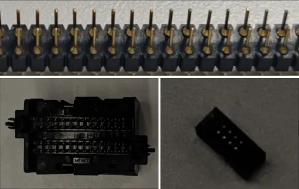
In industrial measurement scenarios, the quality inspection of pins is crucial for the processing and assembly of precision components. The application scenarios of pin height measurement are as follows.
-
Semiconductor manufacturing: In the semiconductor manufacturing process, pins are often used to connect wafers and carrier plates. It is necessary to precisely measure the height and position of pins to ensure good electrical connections and prevent wafer damage.
-
Electronic equipment assembly: During the assembly of electronic devices, pins may be used to secure or connect small electronic components. Measuring the height and position of pins helps ensure the correct placement and fixation of components.
-
Aerospace: In the aerospace field, component accuracy is crucial to flight safety, and measuring the height of pins helps ensure high-precision fitting and connection of components.
-
Precision instruments: In precision instruments, pins may be used for positioning or connecting key components. Measuring the height and position of pins contributes to ensuring the performance and accuracy of the instruments.
In summary, pin quality inspection has wide-ranging applications, and pin height measurement is a vital part of pin quality inspection.
Solution Design
Select the Laser Profiler Model
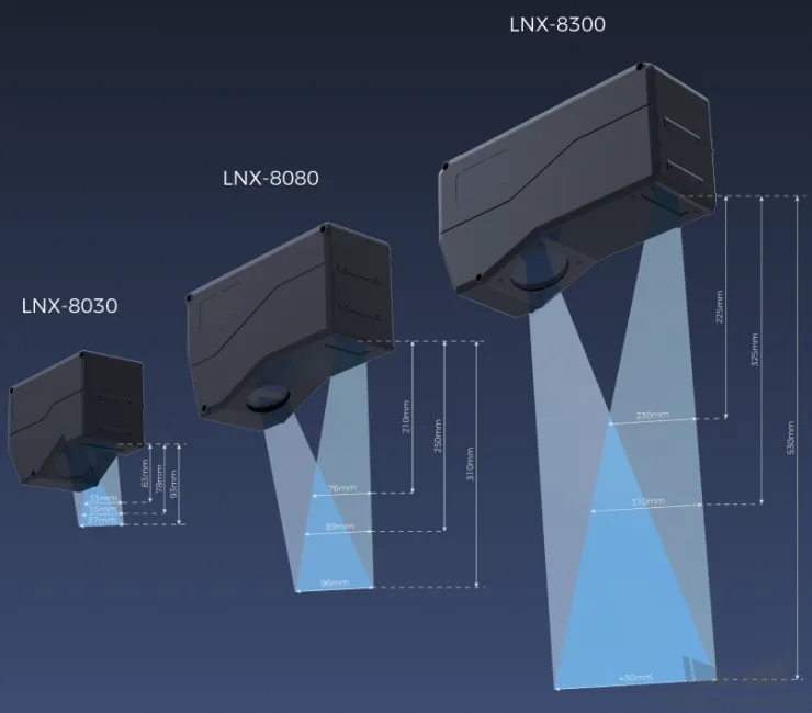
When selecting a laser profiler, the laser profiler’s X-axis measurement range should be greater than the length or width of the object to be measured, and the long side of the laser profiler typically aligns with the long side of the object to be measured.
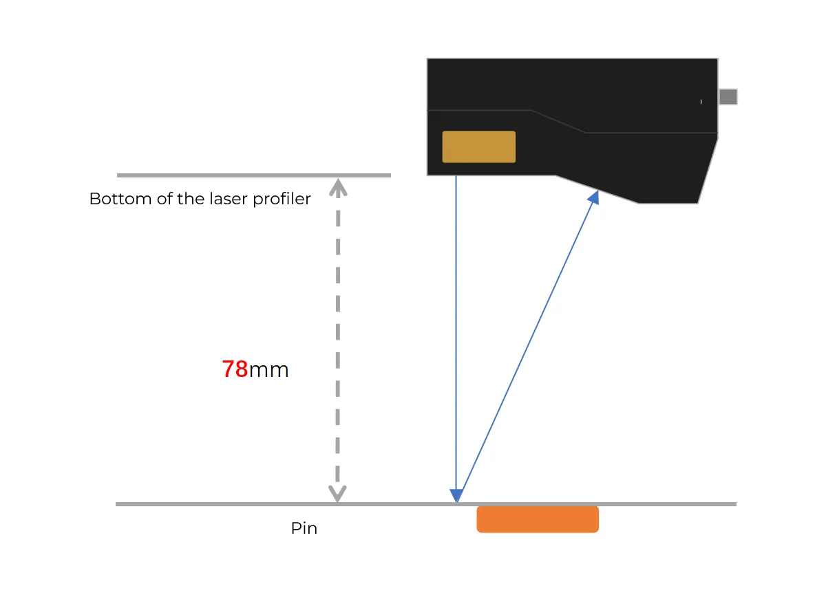
The following figure illustrates the field of view for various models of sensor heads in the LNX-8000 series. Since the dimensions of the target object to be measured are 18 mm × 5 mm, to ensure that the laser profiler’s field of view can completely cover the target object, model LNX-8030 is recommended.
Mounting Method of Laser Profiler
You can mount the laser profiler at a fixed location or mount it on a moving rail. Please select the mounting method according to the actual situation. For this solution, the laser profiler is mounted at a fixed location.
Laser Profiler Triggering
The laser profiler supports multiple triggering methods, allowing it to be integrated into a system and work with other devices flexibly to obtain the intensity image, depth map, and point cloud. In this solution, the external + encoder method is used to trigger data acquisition. The detailed instructions are as follows.
-
Set parameters in Mech-Eye Viewer.
-
Set the Data Acquisition Trigger Source parameter to External.
-
Set the Line Scan Trigger Source parameter to Encoder.
-
Based on actual needs, adjust other parameters in the scan mode.
-
-
Set the parameters of the 3D Laser Profiler Step.
-
In the Parameters section, click Open the editor to select and connect the laser profiler you want.
-
Activate Data Acquisition Status to enable the laser profiler to receive external signals, triggering data acquisition once the signal is received.
-
-
Run the measurement project, and the external signal triggers the laser profiler to acquire data.
-
Once data acquisition is complete, the data will be transferred to Mech-MSR.
Solution Deployment
Measurement Project Configuration
Workflow Overview
In this solution, the laser profiler is used to acquire the depth map first. Then the acquired depth map will be input to the Blob Analysis Step to locate the pins and obtain their feature points. At the same time, a specific region will be selected to fit the reference plane, and thus the height of the pin to the reference plane can be measured.
The following figure shows the overall workflow.
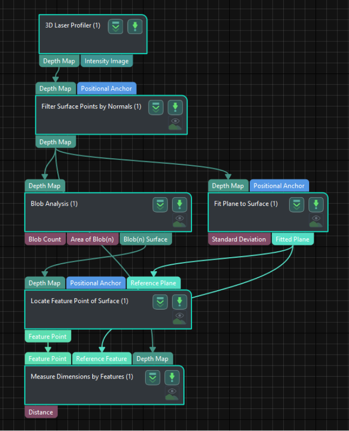
The key Steps in the workflow are described below.
Step Description
Fit Plane to Surface
-
Function:
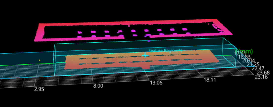
This Step uses the surface information of the custom region to fit a reference plane. As shown in the figure below, the semi-transparent plane is the fitted plane.

-
Usage Procedure:
-
Add a feature region.
-
Move the feature region to the desired measurement region.
-
Select Fitted Plane in the Output section.
-
-
Check Output Result:
The output result of this Step is shown in the figure below. The semi-transparent plane is the fitted plane.
Measure Dimensions by Features
-
Function:
This Step is used to perform dimensional measurements from a feature point (pin) to a reference feature (fitted plane).
-
Usage Procedure:
-
Select the Feature Point and Reference Feature in the Input section.
-
Select Distance in the Output section.
-
-
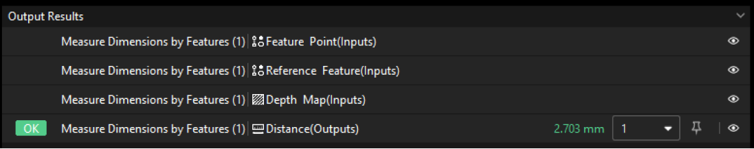
Check Output Result:
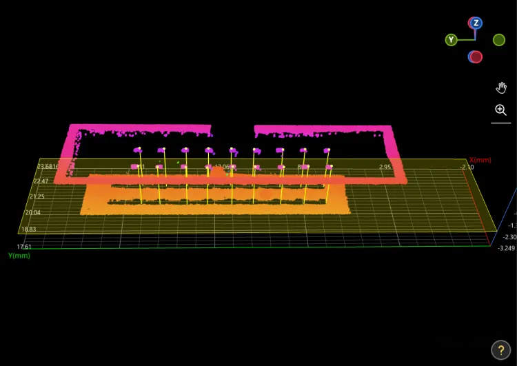
The output result of this Step is shown in the figure below. The semi-transparent yellow plane is the fitted plane, and the yellow line indicates the distance from the pin to the plane.
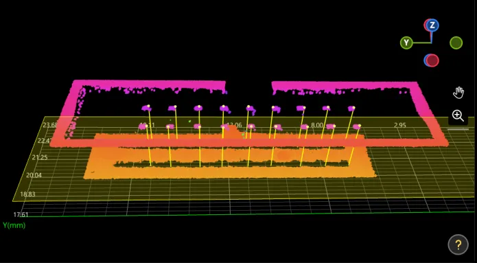
The measured height of pin is 2.703 mm.
Configure Quality Judgment Rules
After adjusting the Step parameters, you need to configure the quality judgment rules for outputting the measurement and inspection results.
-
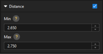
In the Output section of the “Measure Dimensions by Features” Step, set the acceptable range for Distance.
In the collapsible tab of Distance, set the maximum and minimum values allowed for the measurement results. When the measured value is within the acceptable range, the inspection result is OK. Maximum and minimum values need to be set according to the drawing and process requirements of the target object.
-
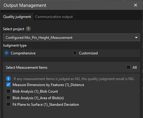
Go to Output Management and set the Judgment type to Comprehensive.
Since only the distance is inspected in this solution, “0” (OK) will be sent to the external device when all inspection results are OK.
-
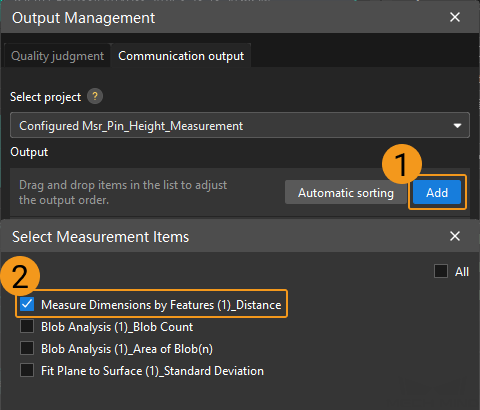
Output measurement results (optional).
If external devices require access to measurement results, the measurement items need to be added as output. To do so, go to to add the measurement item as shown below.
Communication Configuration
To ensure smooth communication between Mech-MSR and external devices (PLC or other production line equipment), allowing them to trigger Mech-MSR project executions and retrieve measurement results, communication configuration is also required. For detailed instructions, please refer to Communication Configuration.
Now you have completed configurations related to the measurement project.