Hole Measurement for Metal Parts
This section introduces the basic information, design, and deployment of the Hole Measurement for Metal Parts solution.
Basics
Application Scenario Description
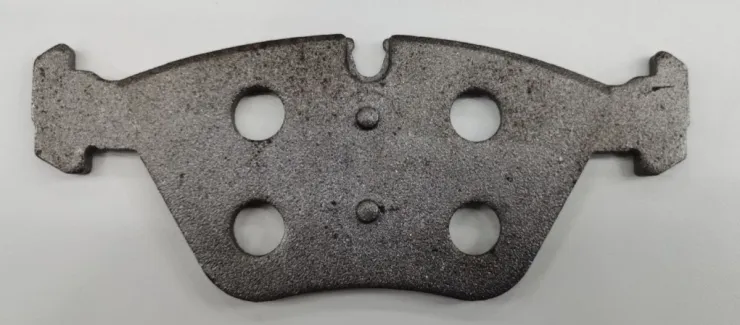
In the processes of mechanical manufacturing and electronic product fabrication, measuring circular hole dimensions is crucial to ensuring the accuracy and quality of components. For instance, in the manufacturing of vehicles like cars and aircraft, precise measurement of the diameter, depth, and position of circular holes is necessary to ensure assembly accuracy and overall performance among components.
Solution Design
Select the Laser Profiler Model
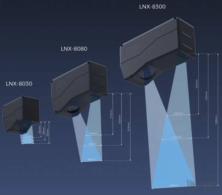
When selecting a laser profiler, the laser profiler’s X-axis measurement range should be greater than the length or width of the object to be measured, and the long side of the laser profiler typically aligns with the long side of the object to be measured.
The following figure illustrates the field of view for various models of sensor heads in the LNX-8000 series. Since the dimensions of the target object to be measured are 150 mm × 60 mm, to ensure that the laser profiler’s field of view can completely cover the target object, model LNX-8080 is recommended.
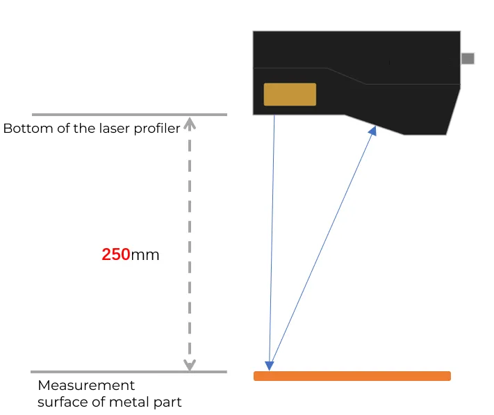
Mounting Method of Laser Profiler
You can mount the laser profiler at a fixed location or mount it on a moving rail. Please select the mounting method according to the actual situation. For this solution, the laser profiler is mounted at a fixed location.
Laser Profiler Triggering
The laser profiler supports multiple triggering methods, allowing it to be integrated into a system and work with other devices flexibly to obtain the intensity image, depth map, and point cloud. In this solution, the external + encoder method is used to trigger data acquisition. The detailed instructions are as follows.
-
Set parameters in Mech-Eye Viewer.
-
Set the Data Acquisition Trigger Source parameter to External.
-
Set the Line Scan Trigger Source parameter to Encoder.
-
Based on actual needs, adjust other parameters in the scan mode.
-
-
Set the parameters of the 3D Laser Profiler Step.
-
In the Parameters section, click Open the editor to select and connect the laser profiler you want.
-
Activate Data Acquisition Status to enable the laser profiler to receive external signals, triggering data acquisition once the signal is received.
-
-
Run the measurement project, and the external signal triggers the laser profiler to acquire data.
-
Once data acquisition is complete, the data will be transferred to Mech-MSR.
Solution Deployment
Measurement Project Configuration
Workflow Overview
In this solution, the laser profiler is used to acquire the depth map first. Then the acquired depth map will be input to the Detect and Measure Hole on Surface Step to measure the holes. In the end, the corresponding measurement results will be output.
The following figure shows the overall workflow.
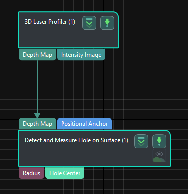
The key Steps in the workflow are described below.
Step Description
Detect and Measure Hole on Surface
-
Function:
This Step is used to detect the hole on a surface and output the location and radius of the detected hole.
-
Usage Procedure:
-
According to the actual situation, set Nominal Radius and Radius Tolerance in the Parameters section.
-
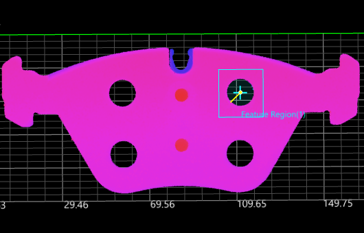
Move the feature region to the location of the hole to be measured.
-
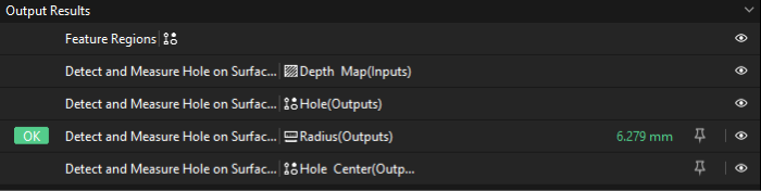
Select Radius and Hole Center in the Output section.
-
-
Check Output Result:
The output result of this Step is shown in the figure below. The yellow circle is the fitted circle for measurement.
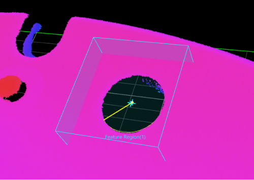
The measured circle radius is 6.279 mm.
Configure Quality Judgment Rules
After adjusting the Step parameters, you need to configure the quality judgment rules for outputting the measurement and inspection results.
-
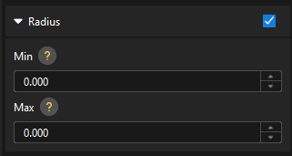
In the Output section of the “Detect and Measure Hole on Surface” Step, set the acceptable range for Radius.
In the collapsible tab of Radius, set the maximum and minimum values allowed for the measurement results. When the measured value is within the acceptable range, the inspection result is OK. Maximum and minimum values need to be set according to the drawing and process requirements of the target object.
-
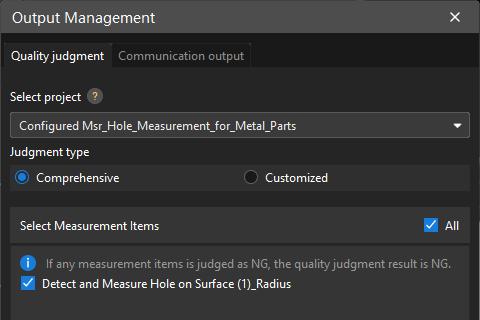
Go to Output Management and set the Judgment type to Comprehensive.
Since only the radius is inspected in this solution, “0” (OK) will be sent to the external device when all inspection results are OK.
-
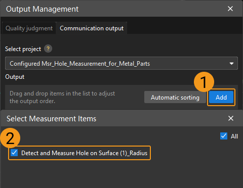
Output measurement results (optional).
If external devices require access to measurement results, the measurement items need to be added as output. To do so, go to to add the measurement item as shown below.
Communication Configuration
To ensure smooth communication between Mech-MSR and external devices (PLC or other production line equipment), allowing them to trigger Mech-MSR project executions and retrieve measurement results, communication configuration is also required. For detailed instructions, please refer to Communication Configuration.
Now you have completed configurations related to the measurement project.