Defect Inspection for Brake Pads (Blob Analysis)
This section introduces the basic information, design, and deployment of the Defect Inspection for Brake Pads (Blob Analysis) solution.
Basics
Application Scenario Description
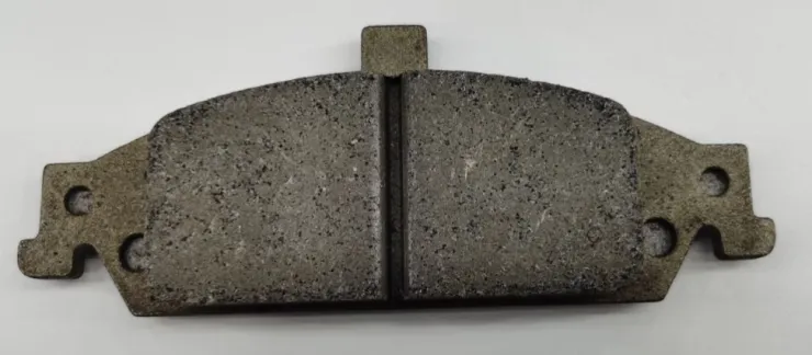
In the process of automobile manufacturing, brake pad defect inspection is employed to ensure the quality of the braking system, meeting relevant safety standards and regulations. By automatically inspecting the surface quality and dimensions of brake pads on the production line, defects or non-compliant products can be detected early and repaired or replaced promptly.
Solution Design
Select the Laser Profiler Model
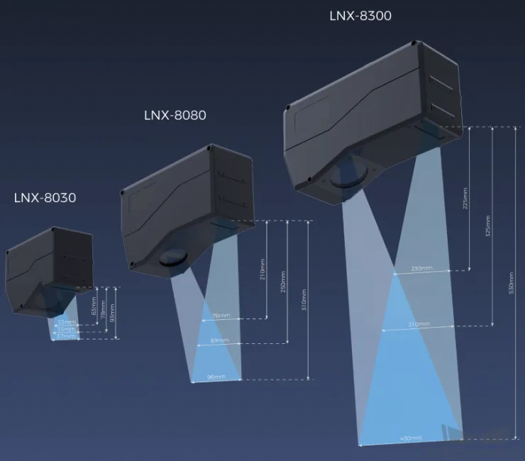
When selecting a laser profiler, the laser profiler’s X-axis measurement range should be greater than the length or width of the object to be measured, and the long side of the laser profiler typically aligns with the long side of the object to be measured.
The following figure illustrates the field of view for various models of sensor heads in the LNX-8000 series. Since the dimensions of the target object to be measured are 150 mm × 60 mm, to ensure that the laser profiler’s field of view can completely cover the target object, model LNX-8080 is recommended.
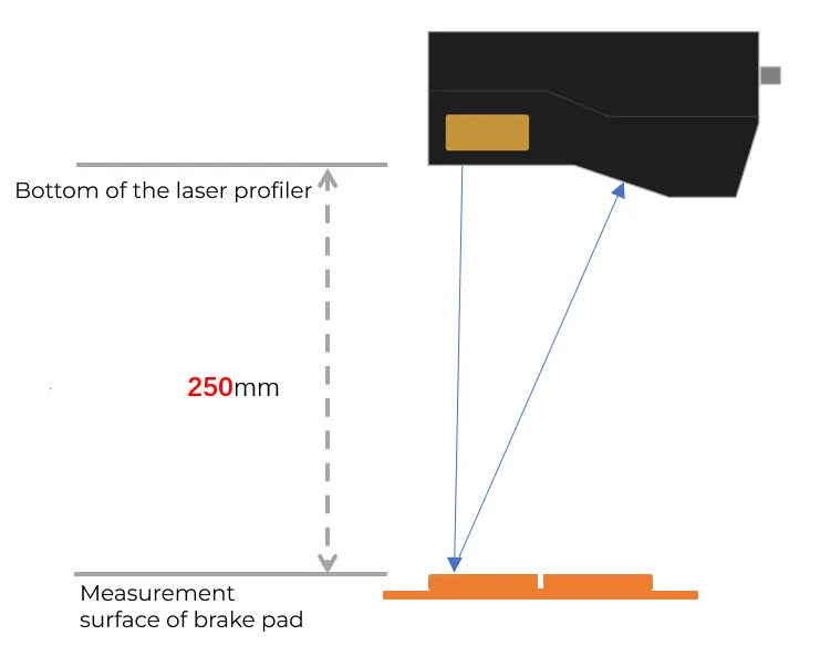
Mounting Method of Laser Profiler
You can mount the laser profiler at a fixed location or mount it on a moving rail. Please select the mounting method according to the actual situation. For this solution, the laser profiler is mounted at a fixed location.
Laser Profiler Triggering
The laser profiler supports multiple triggering methods, allowing it to be integrated into a system and work with other devices flexibly to obtain the intensity image, depth map, and point cloud. In this solution, the external + encoder method is used to trigger data acquisition. The detailed instructions are as follows.
-
Set parameters in Mech-Eye Viewer.
-
Set the Data Acquisition Trigger Source parameter to External.
-
Set the Line Scan Trigger Source parameter to Encoder.
-
Based on actual needs, adjust other parameters in the scan mode.
-
-
Set the parameters of the 3D Laser Profiler Step.
-
In the Parameters section, click Open the editor to select and connect the laser profiler you want.
-
Activate Data Acquisition Status to enable the laser profiler to receive external signals, triggering data acquisition once the signal is received.
-
-
Run the measurement project, and the external signal triggers the laser profiler to acquire data.
-
Once data acquisition is complete, the data will be transferred to Mech-MSR.
Solution Deployment
Measurement Project Configuration
Workflow Overview
In this solution, the laser profiler is used to acquire the depth map first. Then the acquired depth map will be input to the Process Surface by Filter Step to crop the measurement region. Next, the cropped depth map will be input to the Measure Surface Flatness Step to fit a reference plane. Afterwards, the reference plane and depth map will be input to the Blob Analysis Step for depression inspection. In the end, the corresponding measurement results will be output.
The following figure shows the overall workflow.
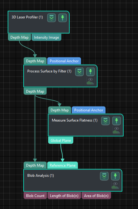
The key Steps in the workflow are described below.
Step Description
Process Surface by Filter
-
Function:
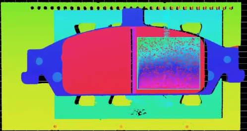
This Step can preprocess the surface to obtain a better surface quality for measurement. The selected region for defect detection is shown in the figure below.
-
Usage Procedure:
-
Select Show Advanced Filters in the Parameters section, and set the Filter Type to Crop.
-
Select Use Feature Region. Then add and move the feature region to the measurement region.
-
Measure Surface Flatness
-
Function:
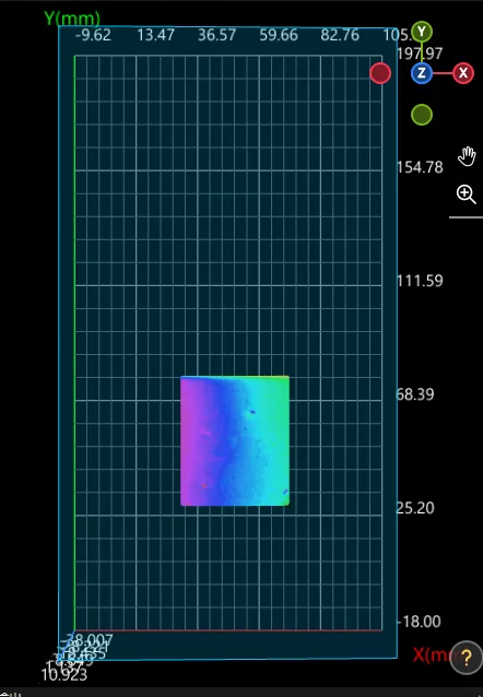
This Step is used to measure the flatness of a specified surface region.
-
Usage Procedure:
-
Unselect Use Feature Region in the Parameters section.
-
According to the actual situation, set Data Filtering Mode to Global percentile in the Parameters section. As there is noise in the measurement region, the surface flatness is calculated after removing the top 20% and bottom 20% points farthest from the fitted plane.
-
Select Global Plane in the Output section.
-
Blob Analysis
-
Function:
This Step can extract blobs or regions of specific shapes and sizes from the image.
-
Usage Procedure:
-
Set the Reference Type to Reference plane in the Parameters section.
-
Set Threshold Filter to Below.
-
Set the Height Threshold according to the actual situation.
-
Set the Max Area and Min Area of the Area Filter according to the actual situation.
-
Select Length of Blob(n) and Area of Blob(n) in the Output section.
-
-
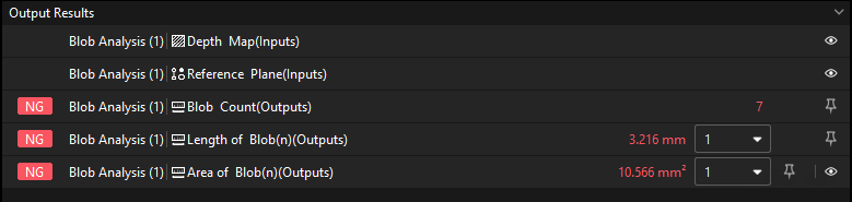
Check Output Result:
The output result of this Step is shown in the figure below. The semi-transparent yellow plane is the reference plane, and the bright blue marks the depression.
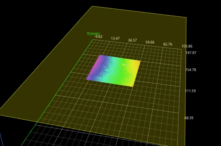
The measured defect length is 3.216 mm, and the measured defect area is 10.566 mm².
Configure Quality Judgment Rules
After adjusting the Step parameters, you need to configure the quality judgment rules for outputting the measurement and inspection results.
-
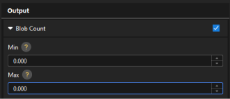
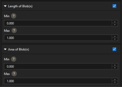
In the Output section of the “Blob Analysis” Step, set the acceptable range for the Blob Count, Length of Blob(n), and Area of Blob(n).
In the collapsible tabs of Blob Count, Length of Blob(n), and Area of Blob(n), set the maximum and minimum values allowed for the measurement results. When the measured value is within the acceptable range, the inspection result is OK. Maximum and minimum values need to be set according to the drawing and process requirements of the target object.
-
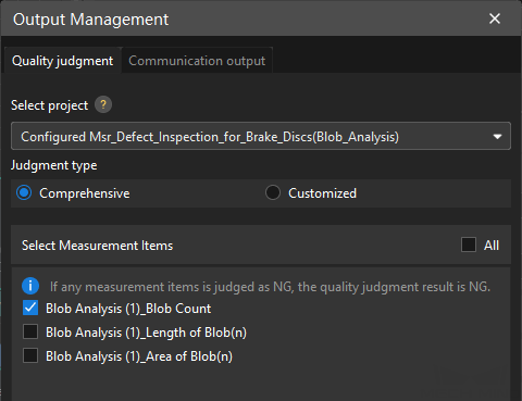
Go to Output Management and set the Judgment type to Comprehensive.
Since only the blob count is inspected in this solution, “0” (OK) will be sent to the external device when all inspection results are OK.
-
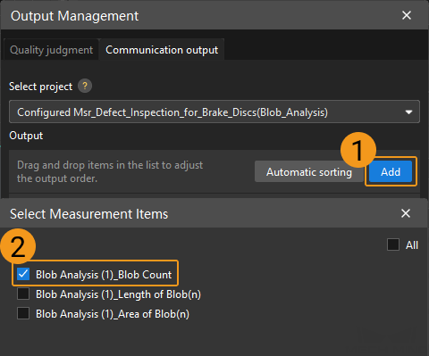
Output measurement results (optional).
If external devices require access to measurement results, the measurement items need to be added as output. To do so, go to to add the measurement item as shown below.
Communication Configuration
To ensure smooth communication between Mech-MSR and external devices (PLC or other production line equipment), allowing them to trigger Mech-MSR project executions and retrieve measurement results, communication configuration is also required. For detailed instructions, please refer to Communication Configuration.
Now you have completed configurations related to the measurement project.