Cap–Terminal Height Measurement for Battery Cells
This section introduces the basic information, design, and deployment of the Cap–Terminal Height Measurement for Battery Cells solution.
Basics
Application Scenario Description
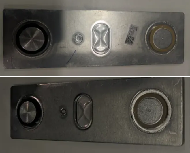
Measuring the height difference between the cap and terminal of the battery cell is an important step in quality control, which is crucial for ensuring the performance and safety of the battery cell. The application scenarios for measuring the height difference between the cap and terminal of the battery cell are as follows.
-
Quality control during manufacturing process: During the battery cell manufacturing process, measuring the height difference can help manufacturers monitor the consistency and integrity of the battery cells. Inconsistent height between the cap and the terminal may lead to uneven battery pack height, affecting battery performance and lifespan. Precise measurement of the height difference enables timely detection and correction of deviations during the manufacturing process.
-
Battery performance evaluation: The height difference between the cap and the terminal of a battery cell may affect the internal structure and electrochemical reactions of the battery, thus impacting its performance. Measuring the height difference of battery cells helps assess key performance indicators such as discharge rate, charging speed, and cycle life.
-
Safety inspection: A large height difference between the cap and the terminal can cause uneven stress during charging and discharging processes, potentially leading to cell rupture or leakage and resulting in safety issues. Therefore, by measuring the height difference between the cap and the terminal, potential safety hazards can be identified in advance to ensure the safe use of battery cells.
In summary, measuring the height difference between the cap and the terminal plays a crucial role in battery manufacturing, performance evaluation, safety inspection, and other processes. Accurate height difference measurement contributes to improving battery performance and safety, aligning with the requirements of sustainable development and green manufacturing.
Solution Design
Select the Laser Profiler Model
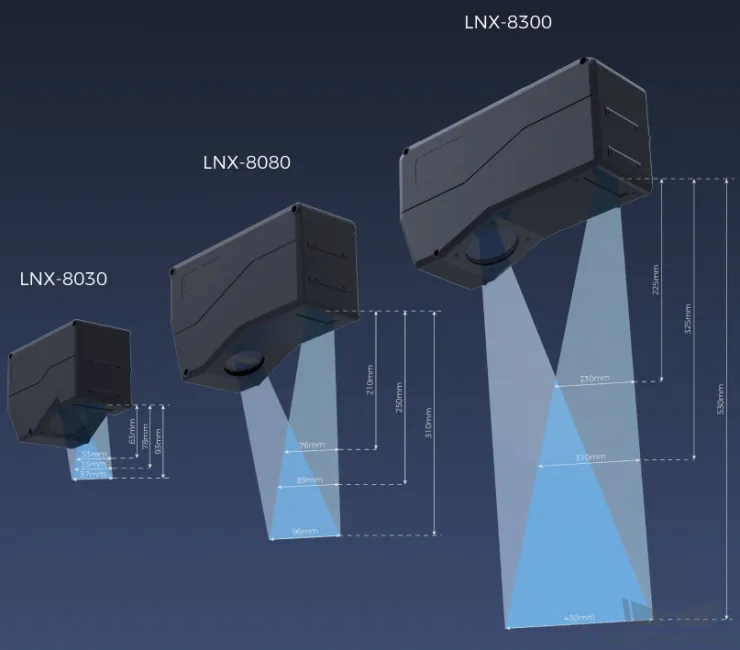
When selecting a laser profiler, the laser profiler’s X-axis measurement range should be greater than the length or width of the object to be measured, and the long side of the laser profiler typically aligns with the long side of the object to be measured.
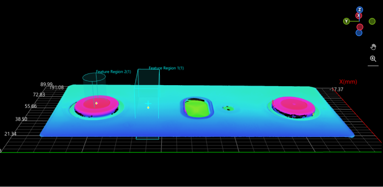
The following figure illustrates the field of view for various models of sensor heads in the LNX-8000 series. Since the dimensions of the target object to be measured are 175 mm × 72 mm, to ensure that the laser profiler’s field of view can completely cover the target object, model LNX-8080 is recommended.
Mounting Method of Laser Profiler
You can mount the laser profiler at a fixed location or mount it on a moving rail. Please select the mounting method according to the actual situation. For this solution, the laser profiler is mounted at a fixed location.
Laser Profiler Triggering
The laser profiler supports multiple triggering methods, allowing it to be integrated into a system and work with other devices flexibly to obtain the intensity image, depth map, and point cloud. In this solution, the external + encoder method is used to trigger data acquisition. The detailed instructions are as follows.
-
Set parameters in Mech-Eye Viewer.
-
Set the Data Acquisition Trigger Source parameter to External.
-
Set the Line Scan Trigger Source parameter to Encoder.
-
Based on actual needs, adjust other parameters in the scan mode.
-
-
Set the parameters of the 3D Laser Profiler Step.
-
In the Parameters section, click Open the editor to select and connect the laser profiler you want.
-
Activate Data Acquisition Status to enable the laser profiler to receive external signals, triggering data acquisition once the signal is received.
-
-
Run the measurement project, and the external signal triggers the laser profiler to acquire data.
-
Once data acquisition is complete, the data will be transferred to Mech-MSR.
Solution Deployment
Measurement Project Configuration
Workflow Overview
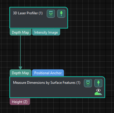
In this solution, the laser profiler is used to acquire the depth map first. Then, the acquired depth map will be input to the Measure Dimensions by Surface Features Step for accurate height measurement. Once the measurement is complete, the corresponding inspection result will be output.
The following figure shows the overall workflow.
The key Steps in the workflow are described below.
Step Description
Measure Dimensions by Surface Features
-
Function:
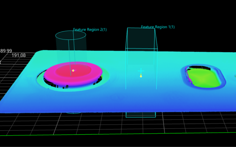
This Step measures and outputs the distance between two feature points in the vertical direction. As shown in the figure below, this Step can measure the distance from feature point 1 to feature point 2.
-
Usage Procedure:
-
Add a feature region.
-
Move the feature region to the desired measurement region.
-
Select Feature Point Type in the Parameters section according to the actual situation.
-
Select Height in the Output section.
-
-
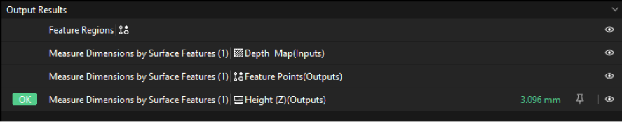
Check Output Result:
The output result of this Step is shown in the figure below. The yellow line indicates the measured height difference.
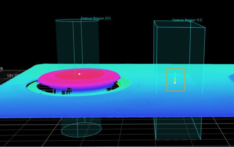
The height difference measured by this Step is 3.096 mm.
Configure Quality Judgment Rules
After adjusting the Step parameters, you need to configure the quality judgment rules for outputting the measurement and inspection results.
-
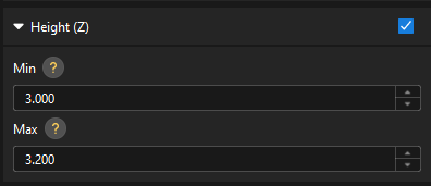
In the Output section, set the acceptable range for Height.
In the collapsible tab of Height, set the maximum and minimum values allowed for the measurement results. When the measured value is within the acceptable range, the inspection result is OK. Maximum and minimum values need to be set according to the drawing and process requirements of the target object.
-
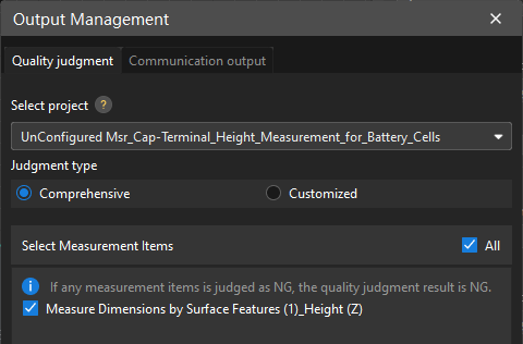
Go to Output Management and set the Judgment type to Comprehensive.
Since only the height is inspected in this solution, “0” (OK) will be sent to the external device when all inspection results are OK.
-
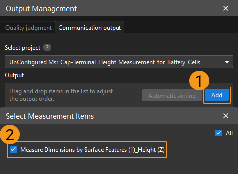
Output measurement results (optional).
If external devices require access to measurement results, the measurement items need to be added as output. To do so, go to to add the measurement item as shown below.
Communication Configuration
To ensure smooth communication between Mech-MSR and external devices (PLC or other production line equipment), allowing them to trigger Mech-MSR project executions and retrieve measurement results, communication configuration is also required. For detailed instructions, please refer to Communication Configuration.
Now you have completed configurations related to the measurement project.