Example 6: MM_S6_Vis_Timer
Program Introduction
Description |
The PLC calculates the vision cycle time, which is the time it takes to trigger the Mech-Vision project to run and obtain the vision result. |
File path |
You can find the program file by using the |
Project |
Mech-Vision project |
Prerequisites |
|
| This example program is provided for reference only. Before using the program, please modify the program according to the actual scenario. |
Program Description
This part describes the MM_S6_Vis_Timer example program.
| The only difference between the MM_S6_Vis_Timer example program and the MM_S1_Vis_Basic example program is that MM_S6_Vis_Timer can calculate the vision cycle time (Network 7). As such, only the feature of calculating the vision cycle time is described in the following part. For information about the parts of MM_S6_Vis_Timer that are consistent with those of MM_S1_Vis_Basic, see Example Program 1: MM_S1_Vis_Basic. |
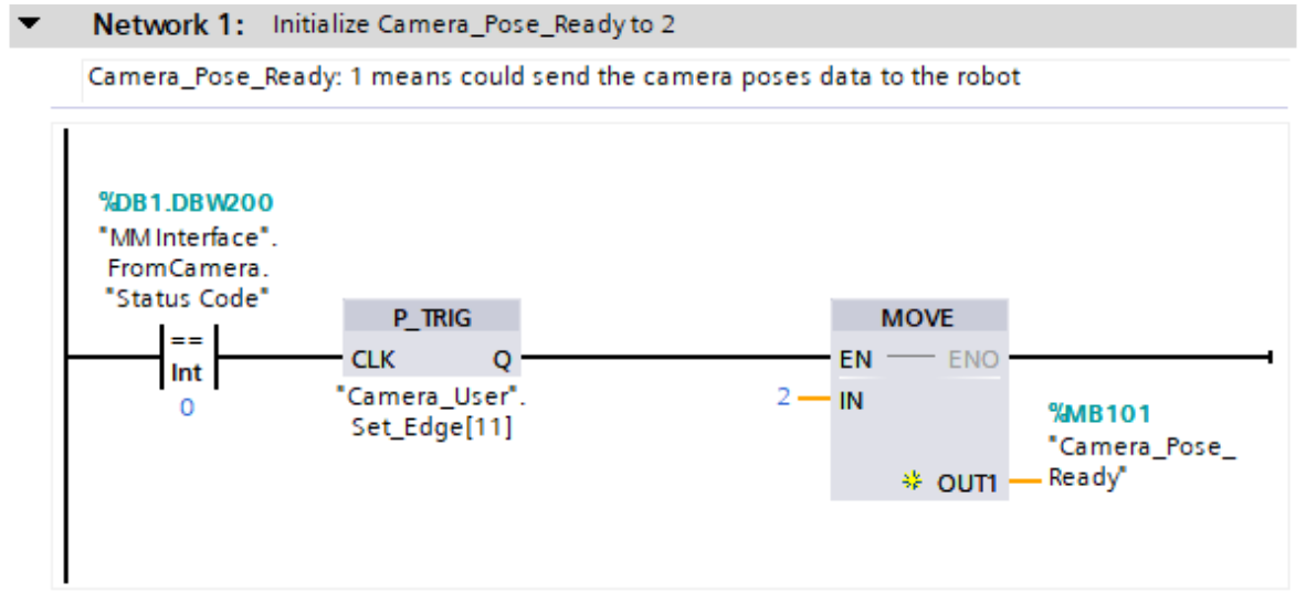

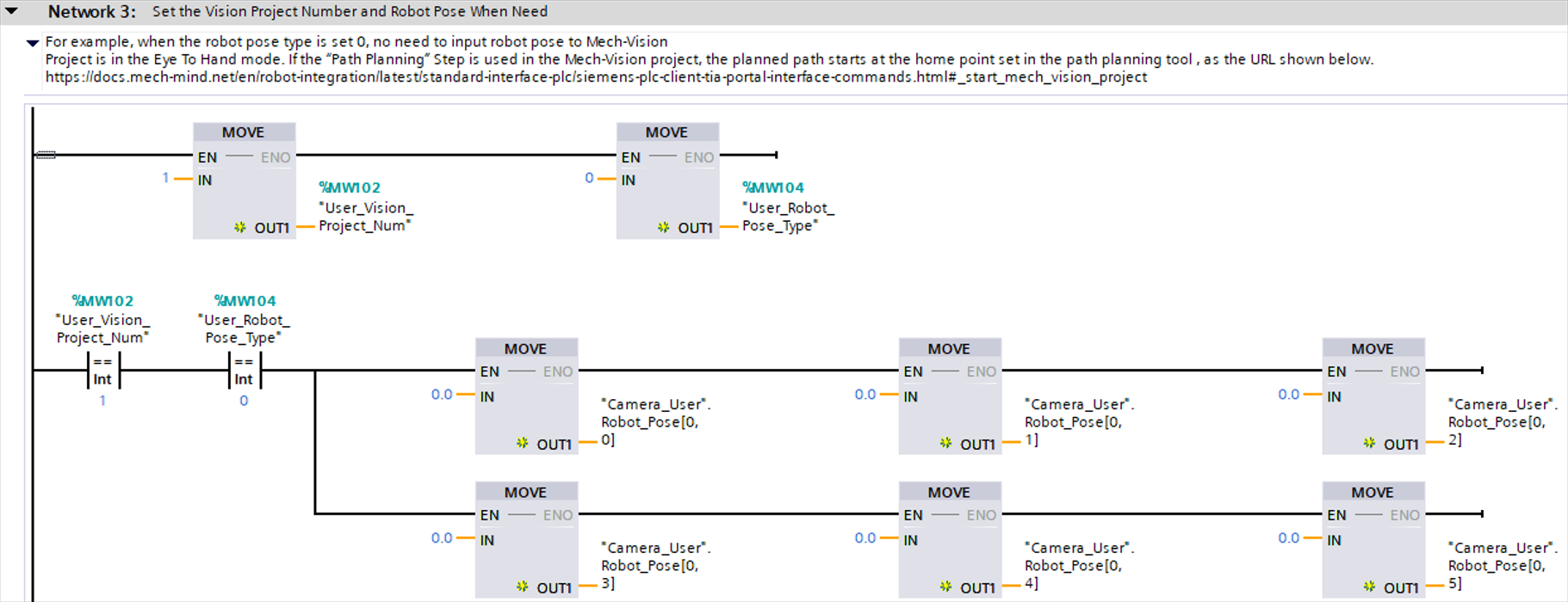
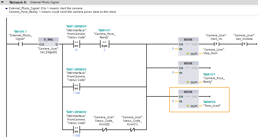
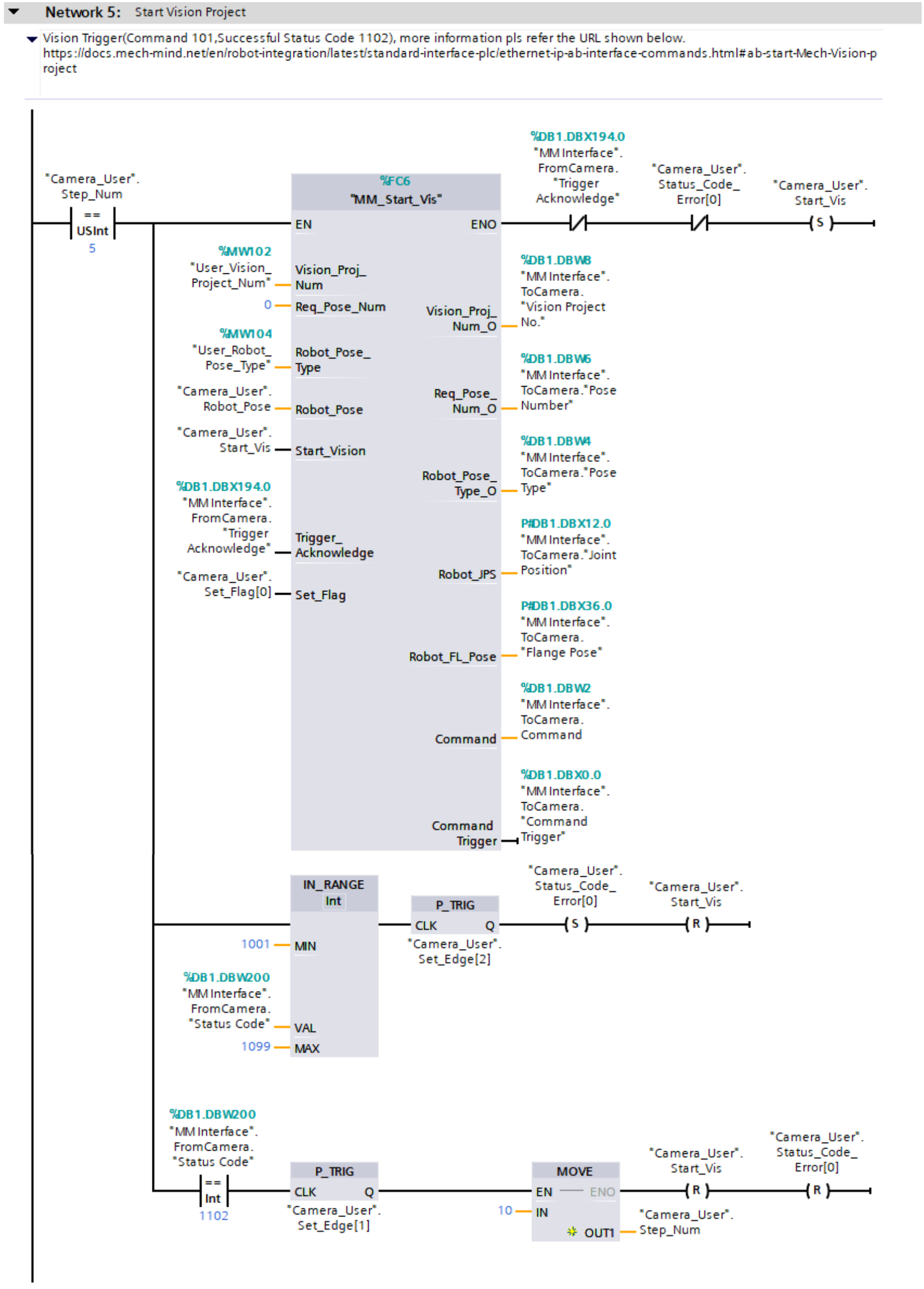
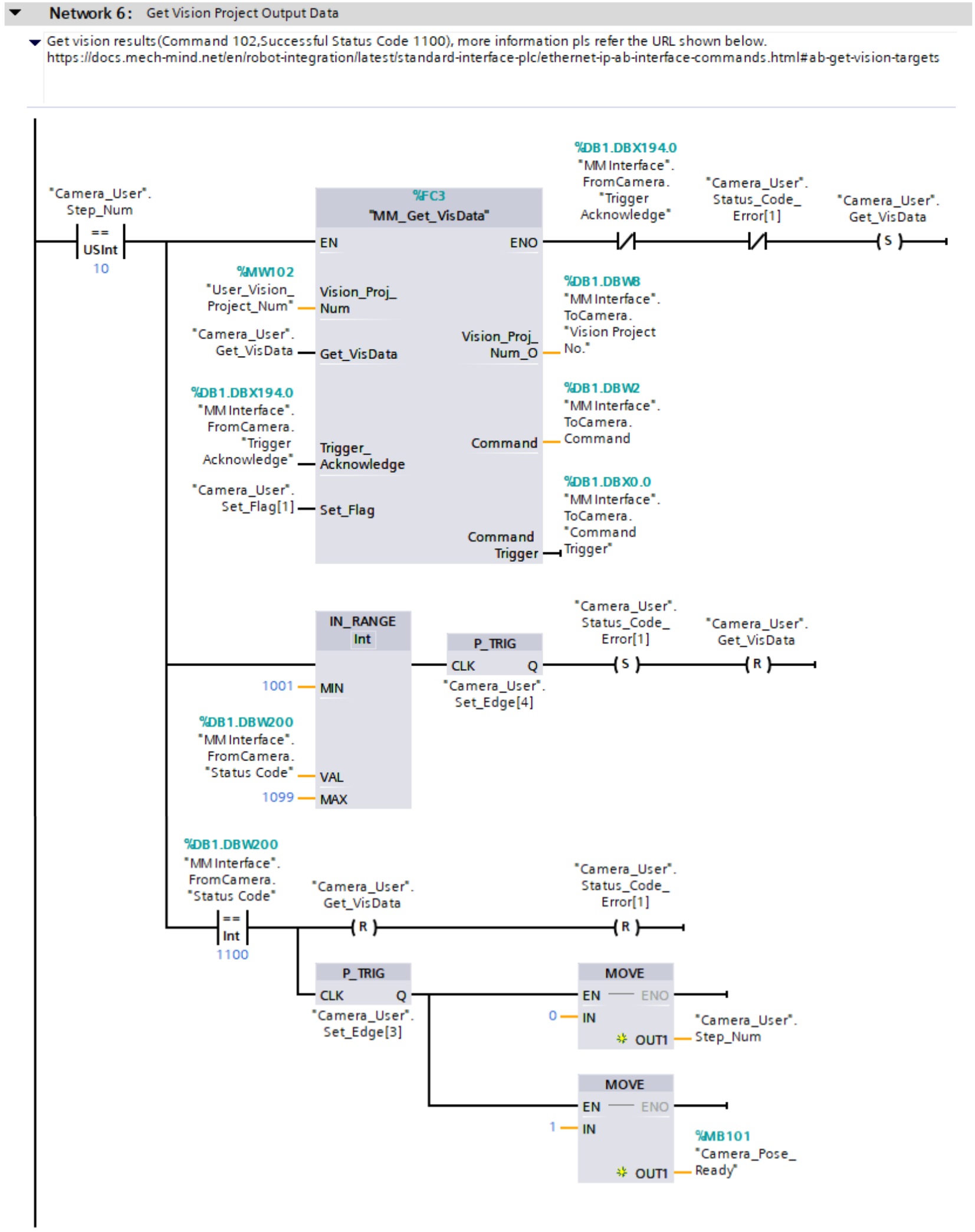
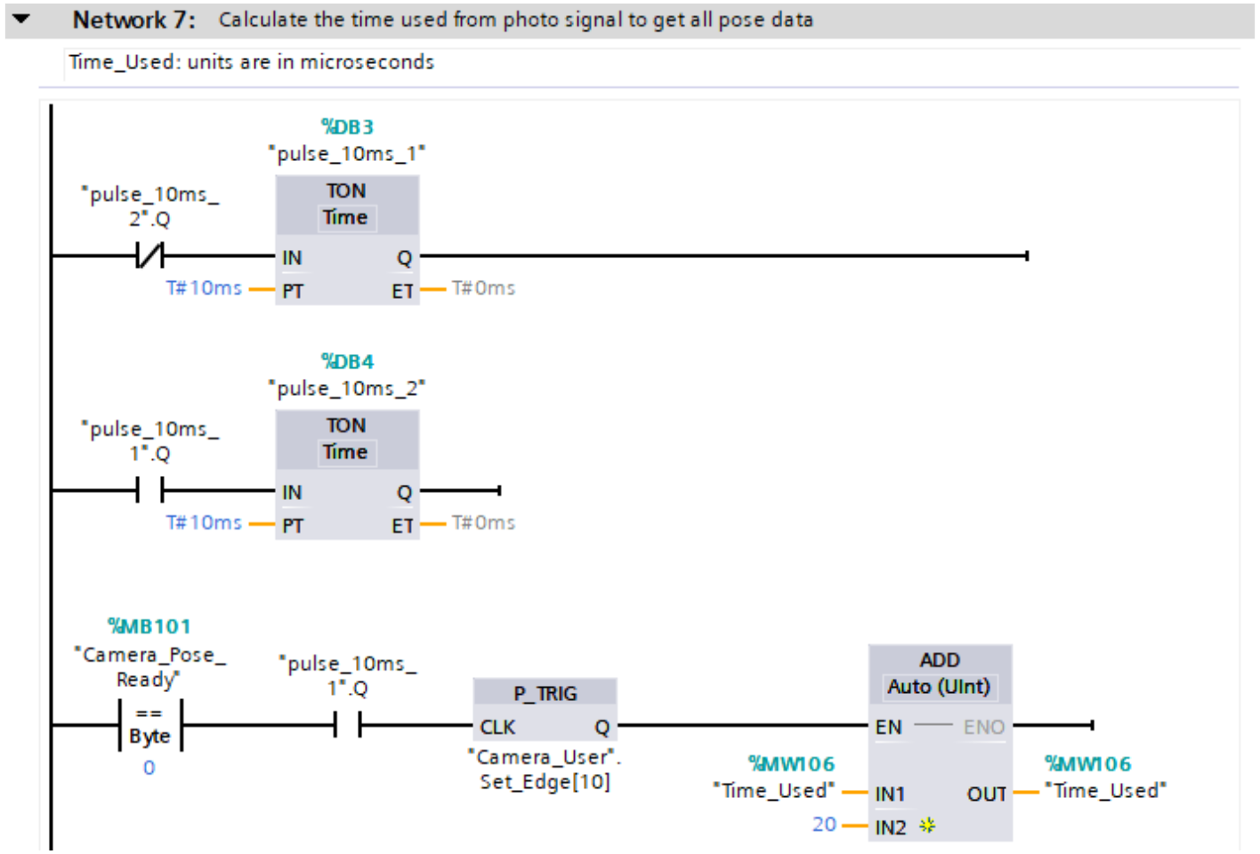
In the above example program, the feature of calculating the vision cycle time is shown in the figure below.

The table below illustrates the process of calculating the vision cycle time.
|
For common commands that come with Siemens S7 Series PLC, see Common Commands. |
| Feature | Description |
|---|---|
Calculate the vision cycle time |

Network 7 indicates that timers are used to calculate the vision cycle time. The following section describes the details.
|