Common Commands
This guide describes the commands commonly used in Siemens S7 Series PLC ladder diagrams, as shown in the following table.
| Ladder diagram | Command | Description |
|---|---|---|
|
Normally open contact |
If IN is True, the normally open contact will close; otherwise, the normally open contact will open. |
|
Normally closed contact |
If IN is False, the normally closed contact will close; otherwise, the normally closed contact will open. |
|
Set |
If S (Set) is activated, OUT will be set to True. If S is not activated, OUT will not change. |
|
Reset |
If R (Reset) is activated, OUT will be set to False. If R is not activated, OUT will not change. |
|
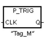
Positive result of logical output (RLO) edge detection |
When a positive transition (0 → 1) is detected on the CLK power flow input, the Q output power flow or logic state is True.
|
|
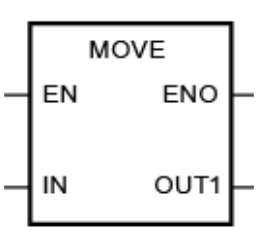
Move |
Copy a single data element from the source address specified by parameter IN to the destination address specified by parameter OUT1. |
|
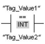
Equal |
If Tag_Value1 equals Tag_Value2, the output will be True; otherwise, the output will be False. |
|
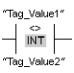
Not equal |
If Tag_Value1 is not equal to Tag_Value2, the output will be True; otherwise, the output will be False. |
|
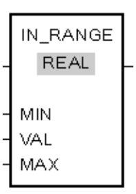
In range |
If the value of VAL is within the range [MIN, MAX], the output will be True; otherwise, the output will be False. |
|
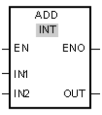
Add |
Perform an addition operation on the input values (IN1 and IN2), and store the result in the memory address specified by the output parameter OUT. |
|
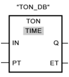
TON |
When IN changes from False to True, the timer starts.
|


