Communication Modes
After you set up the hardware for Mech-Mind Vision System, choose the mode for the vision system to communicate with external devices (such as robots, PLCs, or host computers). The communication helps you manage the data exchange between the two sides. Mech-Mind Vision System supports three communication modes:
| Standard Interface communication and Adapter communication both fall in the category of interface communication. |
Master-Control Communication
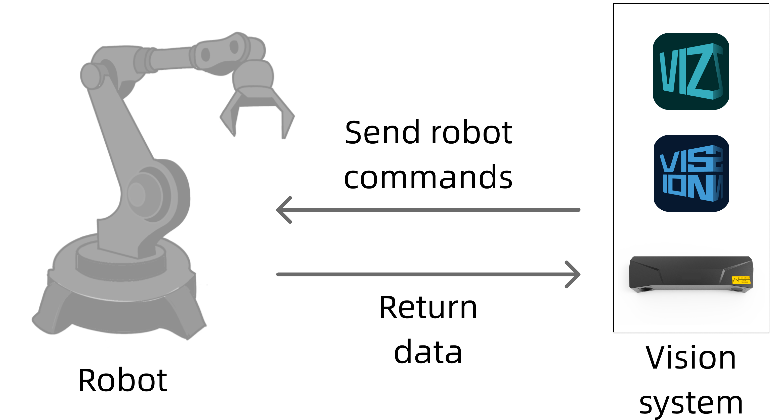
Master-Control communication allows the vision system to control the robot to perform tasks. In this case, the vision system acts as the controller and the robot acts as the controlled party. Specifically, in the Master-Control communication, the vision system sends commands to the robot and the robot listens to, receives, and then executes the commands. The following figure shows this process.

|
Master-Control communication can be implemented by using two methods:
-
Loading-required implementation
In this implementation method, the vision system controls the robot only if Master-Control programs are loaded to the robot and the robot runs the programs throughout the communication process. ABB, FANUC, and KUKA robots use this method to implement Master-Control communication.
-
Loading-free implementation
This implementation method switches the robot to the remote control mode and allows the vision system to use robot SDKs to control the robot without the need to load and run Master-Control programs on the robot. AE and JAKA robots use this method to implement Master-Control communication.
Standard Interface Communication
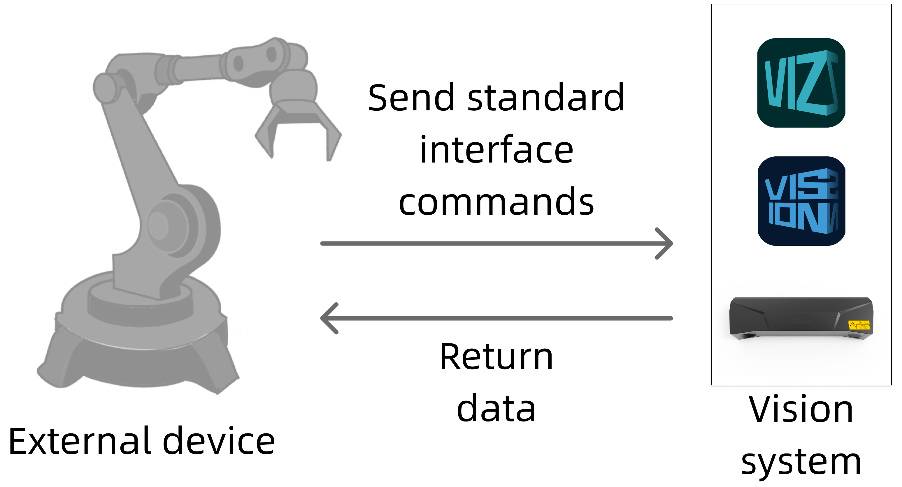
If the Standard Interface communication is established between the vision system and an external device (such as a robot, PLC, or host computer), the external device sends Standard Interface commands to the vision system and the vision system returns data upon receiving the commands. The following figure shows the process. In Standard Interface communication, the vision system only sends data in response to commands from the external device and does not control the external device. For this reason, you need to write programs for an external device to allow the device to communicate with the vision system.
|
Developed by Mech-Mind based on the standard communication protocol, Standard Interface commands define request and response formats. These Standard Interface commands configure Mech-Vision and Mech-Viz projects and return results for the Mech-Vision and Mech-Viz projects. |

You can establish Standard Interface communication by using one of the following two ways:
-
If your eternal device is supported by Mech-Mind Vision System, you can directly use Standard Interface commands. For more information, see Standard Interface Communication.
-
If your external device is not supported by Mech-Mind Vision System, write Standard Interface commands to use Standard Interface communication based on Standard Interface Development Manual.
Adapter Communication
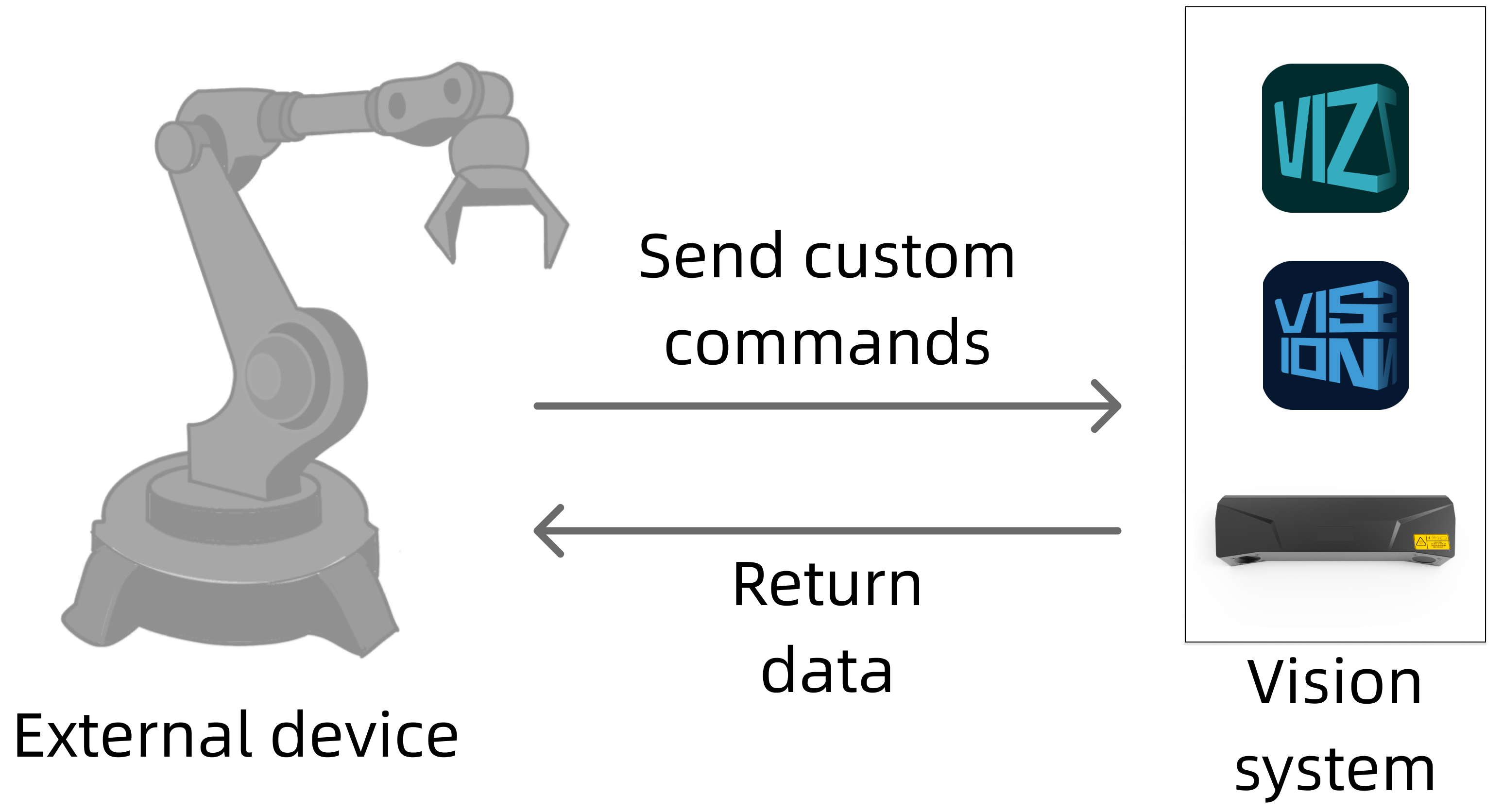
If the adapter communication is established between the vision system and an external device (such as a robot, PLC, or host computer), the external device sends custom commands to the vision system and the vision system returns data upon receiving the commands. The following figure shows the process. In adapter communication, the two sides need to determine the custom commands to use. For this reason, you need to write programs for the external device and the vision system.
|

You can establish adapter communication by using Python in one of the following ways:
-
Use Adapter Generator Guide to configure the command syntax that is used by the two sides for communication. If the generated commands do not meet your requirements, write more commands that suit your needs in Python.
-
Write command syntax that is used by the two sides for communication from scratch based on Adapter Programming Guide.
Comparison between Communication Modes
After the preceding basic introduction to the three communication modes, this section compares the communication modes and summarizes the features and applicable scenarios of each mode to facilitate your understanding.
First, the communication modes differ in the commands that are sent and received by two communication parties. The following table describes the differences.
| Communication mode | Command type | Command sender | Command receiver |
|---|---|---|---|
Master-Control communication |
Robot commands |
Vision system |
Robot |
Standard Interface communication |
Standard Interface commands |
External devices (robots, PLCs, or host computers) |
Vision system |
Adapter communication |
Custom commands |
External devices (robots, PLCs, or host computers) |
Vision system |
Second, the three communication modes differ in their supported protocols, difficulty in use, and flexibility. The following figure shows the differences.
| Communication mode | Supported protocol | Program | Difficulty in use | Flexibility |
|---|---|---|---|---|
Master-Control communication |
TCP and UDP |
No programs are needed |
Low |
Low |
Standard Interface communication |
TCP UDP Siemens PLC Snap7 PROFINET EtherNet/IP Modbus TCP Mitsubishi MC |
Programs need to be written for external devices |
Medium |
Medium |
Adapter Communication |
TCP UDP HTTP WebSocket Siemens PLC Snap7 PROFINET EtherNet/IP Modbus TCP Mitsubishi MC Other communication protocols |
Programs need to be written for the vision system and external devices |
High |
High |
Third, the three communication modes differ in their supported scenarios.
| Communication mode | Workpiece loading | Palletizing & depalletizing | Locating & assembly | Piece picking | Gluing |
|---|---|---|---|---|---|
Master-Control communication |
√ |
√ |
√ |
√ |
√ |
Standard Interface communication |
√ |
√ |
√ |
√ |
× |
Adapter communication |
√ |
√ |
√ |
√ |
√ |
After you get acquainted with the three communication modes, you can select a communication mode that suits your actual needs.