サンプルプログラム11:MM_S11_Viz_Timer
プログラム概要
機能 |
ロボットはタイマーを使用して、通信の確立から把持・配置までの時間を計算します。 |
ファイル場所 |
Mech-VisionとMech-Vizソフトウェアのインストールディレクトリにある |
必要なプロジェクト |
Mech-VisionとMech-Vizプロジェクト |
使用前提 |
|
| このサンプルプログラムは参考用です。ユーザーは実際の状況に応じて、このプログラムを基に変更を加える必要があります。このプログラムをそのまま使用しないでください。 |
プログラム説明
以下はMM_S11_Viz_Timerサンプルプログラムのコードと関連する説明です。
| このサンプルは、MM_S2_Viz_Basicサンプルと比べて、タイマー機能(太字部分のコード)のみが追加されています。そのため、MM_S2_Viz_Basicサンプルと同じ部分のコードについては、以下で再度説明することはありません(詳細は MM_S2_Viz_Basicサンプルの説明 をご参照ください)。 |
DEF MM_S11_Viz_Timer ( )
;---------------------------------------------------
; FUNCTION: trigger Mech-Viz project and get
; planned path, add a timer to record cycle time
; Mech-Mind, 2023-12-25
;---------------------------------------------------
;set current tool no. to 1
BAS(#TOOL,1)
;set current base no. to 0
BAS(#BASE,0)
;move to robot home position
PTP HOME Vel=100 % DEFAULT
;initialize communication parameters (initialization is required only once)
MM_Init_Socket("XML_Kuka_MMIND",873,871,60)
LOOP
;reset timer to 0
$TIMER[1] = 0
;start timer
$TIMER_STOP[1] = FALSE
;move to image-capturing position
LIN camera_capture Vel=1 m/s CPDAT1 Tool[1] Base[0]
;trigger Mech-Viz project
MM_Start_Viz(2,init_jps)
;get planned path, 1st argument (1) means getting pose in JPs
MM_Get_VizData(1,pos_num,vis_pos_num,status)
;check whether planned path has been got from Mech-Viz successfully
IF status<> 2100 THEN
;add error handling logic here according to different error codes
;e.g.: status=2038 means no point cloud in ROI
halt
ENDIF
;save waypoints of the planned path to local variables one by one
MM_Get_Jps(1,Xpick_point1,label[1],toolid[1])
MM_Get_Jps(2,Xpick_point2,label[2],toolid[2])
MM_Get_Jps(3,Xpick_point3,label[3],toolid[3])
;follow the planned path to pick
;move to approach waypoint of picking
PTP pick_point1 Vel=50 % PDAT1 Tool[1] Base[0]
;move to picking waypoint
PTP pick_point2 Vel=10 % PDAT2 Tool[1] Base[0]
;add object grasping logic here, such as "$OUT[1]=TRUE"
halt
;move to departure waypoint of picking
PTP pick_point3 Vel=50 % PDAT3 Tool[1] Base[0]
;move to intermediate waypoint of placing
PTP drop_waypoint CONT Vel=100 % PDAT2 Tool[1] Base[0]
;move to approach waypoint of placing
LIN drop_app Vel=1 m/s CPDAT3 Tool[1] Base[0]
;move to placing waypoint
LIN drop Vel=0.3 m/s CPDAT4 Tool[1] Base[0]
;add object releasing logic here, such as "$OUT[1]=FALSE"
halt
;move to departure waypoint of placing
LIN drop_app Vel=1 m/s CPDAT3 Tool[1] Base[0]
;move back to robot home position
PTP HOME Vel=100 % DEFAULT
$TIMER_STOP[1] = TRUE
offset = 0
SWRITE(str_tmp[], state, offset,"time: %d ms", $TIMER[1])
MM_LOG(str_tmp[])
ENDLOOP
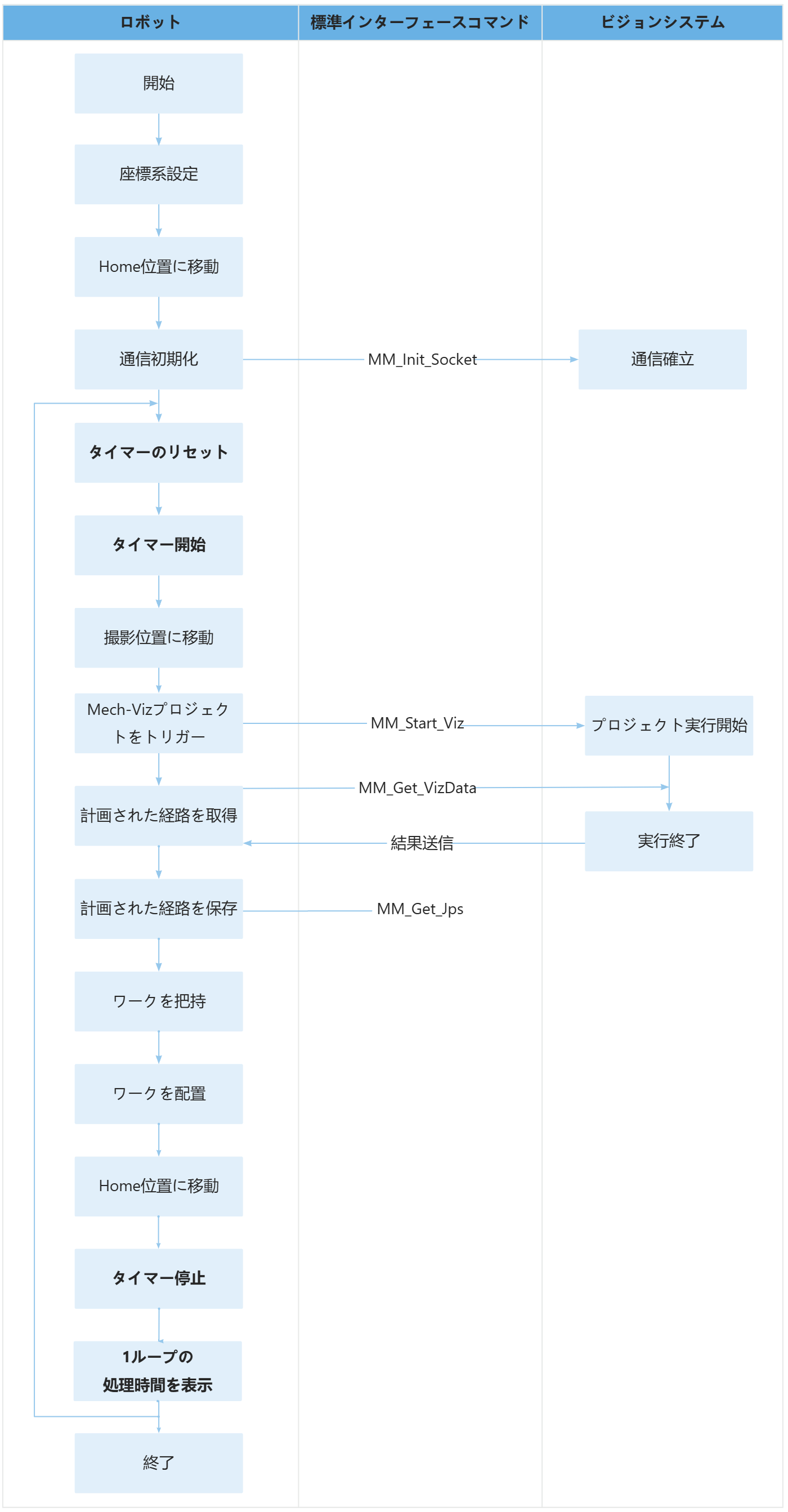
END上記のサンプルプログラムの処理流れは、下図の通りです。
下表は、タイマー機能のコードとその説明です。
| 処理流れ | コートと説明 |
|---|---|
ループで通信確立から把持・配置までの時間を計算 |
上記のコードは、プログラムが「LOOP」と「ENDLOOP」の間のコードを繰り返し実行することを意味します。 上記のコードは、タイマー$TIMER[1]を0ミリ秒にリセットすることを意味します。 上記のコードは、タイマー$TIMER[1]を開始することを意味します。 上記のコードは、タイマー$TIMER[1]を停止することを意味します。
上記のコードは、SWRITEコマンドを使用して、タイマー$TIMER[1]で計測した時間を"time: %d ms"の形式でstr_tmp[]配列に書き込むことを意味します。 上記のコードは、計算された時間をティーチペンダント画面に表示することを意味します。 |