Interface Introduction
The interface of Model Editor consists of the following 5 main parts.
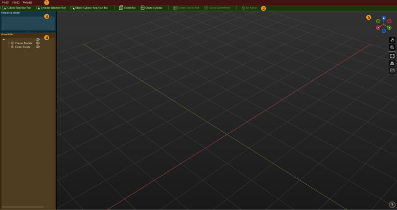
① Menu Bar, ② Toolbar, ③ Reference Model, ④ Assemblies ⑤ 3D Editing Workspace
Menu Bar
Provides functions as importing and exporting the model file, editing, and opening the user guide.
File
| Option | Description | Shortcut |
|---|---|---|
New |
Create a new editing project. |
Ctrl + N |
Open |
Open an existing M3D file to edit. |
Ctrl + O |
Save |
Save the editing project as an M3D file. |
Ctrl + S |
Save As |
Save the editing project as an M3D file to the specified directory. |
Ctrl + Shift + S |
Import |
Reference Model: import the reference model. |
N/A |
Export |
Reference Model: export the reference model; Assemblies: export the assembly. |
N/A |
Toolbar
Provides basic tools for the Model Editor.
| Option | Description | Shortcut |
|---|---|---|
Cuboid Selection Tool |
Creates a cuboid selection. |
N/A |
Elliptic Cylinder Selection Tool |
Creates an elliptic cylinder selection. |
N/A |
Cylinder Selection Tool |
Creates a cylinder selection. |
N/A |
Create Box |
Creates a cuboid convex hull. |
N/A |
Create Cylinder |
Creates a cylinder convex hull. |
N/A |
Create Convex Hull |
Creates a convex hull based on the vertices in the cuboid selection. |
Shift + C |
Create Center Point |
Creates a center point based on the vertices in the cuboid selection. |
N/A |
Create the Reference Frame |
Creates a reference frame based on the center point or the vertices. |
N/A |
Reference Model
The names of the imported files will be displayed in the Reference Model panel.
-
Click the model file name, and the vertices of the model will be displayed in the 3D editing workspace.
-
Once you select the model file name, click
 will hide the model only and the vertices of the model will still be displayed.
 -
If the model file name is not selected, click
will hide the entire model.
Assemblies
The geometric solids, convex hulls, and center point will be displayed in the Assemblies panel. The geometric solid with convex hulls form a convex model.
Click ![]() to hide the corresponding convex hulls or center points.
to hide the corresponding convex hulls or center points.
Right-click the name of the geometric solid and you can see the following options.
| Option | Description | Shortcut |
|---|---|---|
Copy |
Copy the selected geometric solid. |
Ctrl + C |
Paste |
Paste the geometric solid. |
Ctrl + V |
Delete |
Delete the selected geometric solid. |
Delete |
Rename |
Rename the selected geometric solid. |
N/A |
Right-click the name of the convex hull and you can see the following options.
| Option | Description | Shortcut |
|---|---|---|
Copy |
Copy the selected convex hull. |
Ctrl + C |
Paste |
Paste the convex hull. |
Ctrl + V |
Delete |
Delete the selected convex hull. |
Delete |
Rename |
Rename the selected convex hull. |
N/A |
Show 3D Selection Tool At Creation |
Display the 3D selection tool which is used to create the convex hull. |
N/A |
Right-click the name of the center point and you can see the following options in the context menu.
| Option | Description | Shortcut |
|---|---|---|
Copy |
Copy the selected center point. |
Ctrl + C |
Paste |
Paste the center point. |
Ctrl + V |
Delete |
Delete the selected center point. |
Delete |
Rename |
Rename the selected center point. |
N/A |
Show 3D Selection Tool At Creation |
Display the 3D selection tool which is used to create the center point. |
N/A |
Show On Top |
Select to view the center point inside the model. |
N/A |
3D Editing Workspace
The 3D Editing Workspace is used to display and edit the model.
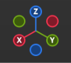
The navigation gizmo shows the current view in the workspace. Click the icon of each axis (X, Y, Z, -X, -Y, -Z) to align the view with the axis. Press and hold the left mouse button and drag the navigation gizmo to rotate the view.
Rotate the view |
Press and hold the scroll wheel and drag in any direction, or press and hold the left mouse button and drag the navigation gizmo in any direction. |
Pan the view |
Press and hold |
Zoom in/out |
Press and hold |
Fit the view |
Click |
Switch to perspective/orthographic view |
Click |
Show pressed keyboard keys and mouse buttons |
Once |