样例程序22:MM_S22_Vis_As_Uframe
程序解读
以下为MM_S22_Vis_As_Uframe样例程序的代码及相关解释说明。
| 与MM_S3_Vis_Path样例相比,本样例仅新增了通过循环获取所有规划路径并进行抓取与放置的功能(加粗部分的代码)。因此,下文不再重复解释与MM_S3_Vis_Path样例相同部分的代码(详情请参考MM_S3_Vis_Path样例说明)。 |
1: !-------------------------------- ;
2: !FUNCTION: trigger Mech-Vision ;
3: !project and get vision result ;
4: !as the uframe 7 ;
5: !Mech-Mind, 2026-1-23 ;
6: !-------------------------------- ;
7: ;
8: !set current uframe NO. to 0 ;
9: UFRAME_NUM=0 ;
10: !set current tool NO. to 1 ;
11: UTOOL_NUM=1 ;
12: !move to robot home position ;
13:J P[1] 100% FINE ;
14: !initialize communication ;
15: !parameters(initialization is ;
16: !required only once) ;
17: CALL MM_INIT_SKT('8','192.168.1.20',30000,5) ;
18: !move to image-capturing position ;
19:L P[2] 1000mm/sec FINE ;
20: !trigger NO.1 Mech-Vision project ;
21: CALL MM_START_VIS(1,0,2,10,53) ;
22: !check whether vision project has ;
23: !been triggered successfully ;
24: IF (R[53]<>1102),JMP LBL[99] ;
25: !get vision result from NO.1 ;
26: !Mech-Vision project ;
27: CALL MM_GET_VIS(1,51,53) ;
28: !check whether vision result has ;
29: !been got from Mech-Vision ;
30: !successfully ;
31: IF (R[53]<>1100),JMP LBL[99] ;
32: !save first vision point data to ;
33: !local variables ;
34: CALL MM_GET_POS(1,60,70,80) ;
35: !move to intermediate waypoint ;
36: !of picking ;
37:J P[3] 50% CNT100 ;
38: ;
39: !set the uframe for camera ;
40: UFRAME[7]=PR[60] ;
41: UFRAME_NUM=7 ;
42: ;
43: !move to approach waypoint ;
44: !of picking ;
45:L P[6] 1000mm/sec FINE Tool_Offset,PR[1] ;
46: !move to picking waypoint ;
47:L P[6] 300mm/sec FINE ;
48: !add object grasping logic here, ;
49: !such as "DO[1]=ON" ;
50: PAUSE ;
51: !move to departure waypoint ;
52: !of picking ;
53:L P[6] 1000mm/sec FINE Tool_Offset,PR[1] ;
54: ;
55: !change the uframe ;
56: UFRAME_NUM=0 ;
57: ;
58: !move to intermediate waypoint ;
59: !of placing ;
60:J P[4] 50% CNT100 ;
61: !move to approach waypoint ;
62: !of placing ;
63:L P[5] 1000mm/sec FINE Tool_Offset,PR[2] ;
64: !move to placing waypoint ;
65:L P[5] 300mm/sec FINE ;
66: !add object releasing logic here, ;
67: !such as "DO[1]=OFF" ;
68: PAUSE ;
69: !move to departure waypoint ;
70: !of placing ;
71:L P[5] 1000mm/sec FINE Tool_Offset,PR[2] ;
72: !move back to robot home position ;
73:J P[1] 100% FINE ;
74: END ;
75: ;
76: LBL[99:handling error] ;
77: !add error handling logic here ;
78: !according to different ;
79: !error codes ;
80: !e.g.: mm_status=1003 means no ;
81: !point cloud in ROI ;
82: !e.g.: mm_status=1002 means no ;
83: !vision results ;
84: !e.g.: mm_status=3099 means ;
85: !failed to open socket ;
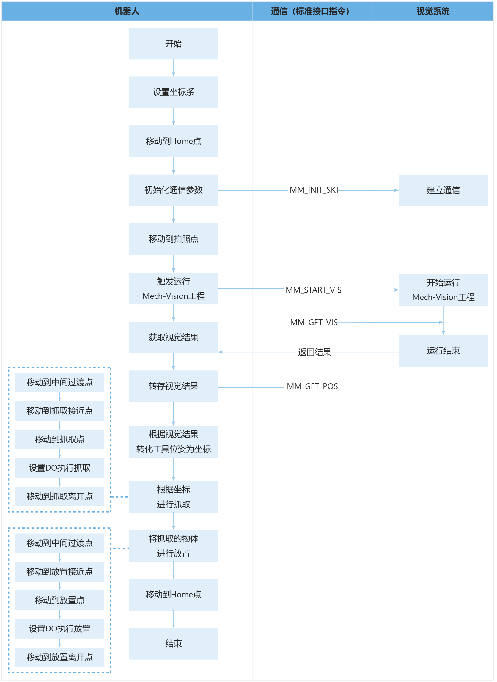
86: PAUSE ;上述样例程序代码对应的流程如下图所示。
下表为新增功能的逻辑解读。用户单击指令名称的超链接便可查看该指令的详细说明。
| 流程 | 代码及说明 |
|---|---|
设置视觉坐标系 |
|
进行抓取和放置 |
上述代码表示,机器人先切换到视觉匹配的用户坐标系完成抓取操作,再切回默认坐标系执行放置操作,最终回到原点结束程序。UFRAME[7]=PR[60]将视觉识别得到的位姿数据赋值给用户坐标系7,UFRAME_NUM=7激活该视觉坐标系,使后续抓取动作基于视觉识别的工件位置执行;抓取完成后UFRAME_NUM=0切回机器人基坐标系,确保放置动作基于预设的基准位置执行。Tool_Offset,PR[1]和Tool_Offset,PR[2]分别为抓取、放置环节的工具偏移参数,用于控制机器人末端在接近/离开工件时的安全偏移量,避免碰撞。 |